

Page 1
SERVICE MANUAL
& PARTS LIST
REF. NO. S/M-781
SEP. 2002
MODULE NO.
QW-1424
DW-6100CF
R
(WITHOUT PRICE)
Page 2

CONTENTS
Page
1. SPECIFICATIONS: MODULE QW-1424 .................................................... 1
2. OPERATION CHART: MODULE QW-1424 ............................................... 1
3. DRAWINGS AND SPECIFICATIONS: MODULE QW-1424
3-1. BLOCK DIAGRAMS...................................................................................... 2
3-2. CHECKING TERMINALS AND COMPONENTS .......................................... 3
4. EXPLODED VIEW: MODULE QW-1424 .................................................... 4
5. PARTS LIST: MODULE QW-1424 ............................................................. 5
6. PRECAUTIONS FOR REPAIR: MODULE QW-1424
6-1. AC (ALL CLEAR) AND REMOVING OF MODULE ...................................... 6
6-2. ACCURACY CHECKING .............................................................................. 6
Page 3
1. SPECIFICATIONS: MODULE QW-1424
Item Detail
Battery CR2016C
Battery life Approx. 3 years
Current consumption 1.90 µA maximum
Alarm system Piezo plate on Back cover
Accuracy ± 15 sec./month
Accuracy setting system Trimmer capacitor
Accuracy checking See page 6
Accuracy setting + 0.25 ~ + 0.35 sec./day
Functions: • Thermometer
Display range: – 20 °C to 130 °C
Display unit: 0.1 °C
• Sunrise and sunset data:
(Sunrise/sunset times based on input data)
2. OPERATION CHART: MODULE QW-1424
Please refer to Service Manual S/M-534 for QW-1414.
The difference between QW-1414 and QW-1424 are the following.
QW-1414 .........Can be switched between Celsius (°C) and Fahrenheit (°F).
QW-1424 .........Can not be switched.
— 1 —
Page 4

3. DRAWINGS AND SPECIFICATIONS: MODULE QW-1424
3-1. BLOCK DIAGRAMS
— 2 —
Page 5

3-2. CHECKING TERMINALS AND COMPONENTS
6. Cushion
(7218 0224)
LA
VDD
LA
11. Micro lamp
(7104 0097)
2. P.C.B. with
components
(7640 5643)
4. Quartz oscillator
Xtal
(7110 1177)
CT
3. Trimmer capacitor
(7103 0458)
N1
N2
N3
N4
A1
A2
A3
XT
XT
VDD
NC
CRST
Transistor
Tr
C2
Chip capacitor
Coil
L Chip capacitor
VSS2
L
4U
VDD
RVR
CRMS
VDD
L
VAN
BD1
VSS2
VDD
XTB
CRIN
CRIN
RVR
CRST
C3
A
LD
VSS1
VDD
VCC
VDD VCH
VC
VSS3
KI8
VDD
LA
LA
KI7
KI6
Thermistor
CST
Chip capacitor
RST
RVR
Chip resistor
RTH
Variable resistor
C4
Tantalum capacitor
Tantalum capacitor
C5
C1
Chip capacitor
Chip resistor
R
Top view of P.C.B. Ass'y Bottom view of P.C.B. Ass'y
— 3 —
Page 6

4. EXPLODED VIEW: MODULE QW-1424
20 (7212 7561)
13 (7212 7657)
12 (7212 7649)
17 (7042 0155)
9 (7218 1857)
1 (7001 2963)
10 (7010 4685)
15 (7215 5056)
12 (7212 7649)
13 (7212 7657)
14 (7212 7665)
8 (7211 0064)
16 (7207 8742)
2 (7640 5643)
P.C.B. with components
5 (7225 1768)
19 (7201 9687)
18 (7201 9679)
Battery (CR-2016C)
7 (7211 9631)
— 4 —
Page 7

5. PARTS LIST: MODULE QW-1424
-
(-)
p
Note: 1. Prices and specifications are subject to change without prior notice.
2. Spare parts are classified as follows according to their importance in after-sales service.
A Rank ---------------------------------------- Very Important
B Rank ---------------------------------------- Important
C Rank ---------------------------------------
3. Batteries in Bulk pack on the tray will be supplied from our Overseas Spare Parts Section under charge basis.
Batteries in Blister pack will be supplied from our Sales Department.
4. As for order/supply of spare parts, refer to the separate publication "GUIDE BOOK for spare parts supply".
Item Code No. Parts Name Specification Applicable Q R
7640 3092 MODULE/WITHOUT MOVEMENT QW-1424DF-01TK DW-6100CF-3/8 1 A
1 7001 2963 LCD S974-03TTP QW-1424DF-01TK 1 A
2 7640 5643 PCB ASS'Y Q250766*1TK QW-1424DF-01TK 1 A
3 7103 0458 CAPACITOR/TRIMMER TSF-2L2-120-4.2 QW-1424DF-01TK 1 B
4 7110 1177 OSCILLATOR/CRYSTAL DT-26S04 QW-1424DF-01TK 1 B
5 7225 1768 CONTACT/BATTERY
6 7218 0224 CUSHION/503 Q49959-1 QW-1424DF-01TK 1 C
7 7211 9631 CUSHION/506 Q49364-1 QW-1424DF-01TK 1 C
8 7211 0064 CUSHION/6 Q4914-1 QW-1424DF-01TK 1 C
9 7218 1857 CUSHION/974-1 Q431447-1 QW-1424DF-01TK 2 C
10 7010 4685 INTERCONNECTOR Q465459-1 QW-1424DF-01TK 2 C
11 7104 0097 LAMP/MICRO MLA-7B QW-1424DF-01TK 1 C
12 7212 7649 PLATE/SWITCH 974-1 Q431234-1 QW-1424DF-01TK 2 C
13 7212 7657 PLATE/SWITCH 974-2 Q431235-1 QW-1424DF-01TK 2 C
14 7212 7665 PLATE/TERMINAL Q333242A-1 QW-1424DF-01TK 1 C
15 7215 5056 REFLECTOR/974 FG30-974P QW-1424DF-01TK 1 C
16 7207 8742 SCREW/910 Q426737-1 QW-1424DF-01TK 4 C
17 7042 0155 SCREW/TAPPING Q41054A-1 QW-1424DF-01TK 4 C
18 7201 9679 SPRING/COIL 974-1 Q431453-1 QW-1424DF-01TK 1 B
19 7201 9687 SPRING/COIL 974-2 Q431454-1 QW-1424DF-01TK 1 B
20 7212 7561 SUPPORTER/LCD Q331460A-1 QW-1424DF-01TK 2 C
BATTERY/LITHIUM CR2016C QW-1424DF-01TK 1
Less important
Q34225D-1 QW-1424DF-01TK 1 C
For the
Notes: Q - Used quantity
rices and minimum order/supply quantities of the above parts, refer to the Parts Price List P.P.L.-586.
R - Rank
— 5 —
Page 8
6. PRECAUTIONS FOR REPAIR: MODULE QW-1424
6-1. AC (ALL CLEAR) AND REMOVING OF MODULE
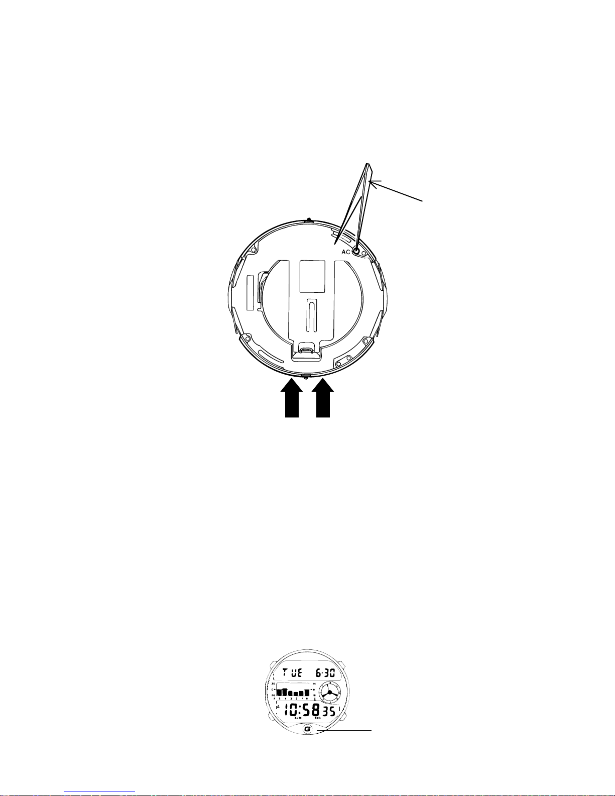
1. Perform AC (ALL CLEAR) when inserting a new battery, or else the memories and/or counters may give
erratic displays.
Touch the AC contact and the positive (+) side of the battery or main plate with the metallic tweezers.
The contact should be made for about two seconds.
2. On removing of the module from the case, please insert the precision screw driver between the module
and the case pointed by arrows.
Metallic tweezers
6-2. ACCURACY CHECKING
Check the accuracy of the module with the quartz timer after switching the module to “ACCURACY
CHECKING MODE”.
The operations are shown below:
A) SWITCHING TO “ACCURACY CHECKING MODE”
Continuously push the A, B and C buttons at the same time at the normal time keeping mode.
Then all the segments are displayed and the LCD drive signals are changed to the static drive signal
of “32 Hz” so that you can check the accuracy with the quartz timer.
B) CANCELLATION OF THE “ACCURACY CHECKING MODE”
Push any button.
Then the display is returned to its original state.
NOTE: The “ACCURACY CHECKING MODE” will automatically return to the regular mode in
1 ~ 2 hour(s) without any operation.
A
C
B
D
Sensor
— 6 —
Page 9

CASIO TECHNO CO.,LTD.
Overseas Service Division
Nishi-Shinjuku Kimuraya Bldg. 1F
5-25, Nishi-Shinjuku 7-Chome
Shinjuku-ku, Tokyo 160-0023, Japan
 Loading...