

Page 1

CASIO
DT-X7 Series
Quick Start Guide
(Version 1.18)
CASIO Computer Co., Ltd.
Copyright ©2012. All rights reserved.
April 2012
Page 2

2
Table of the Contents
Editorial Record 4
Preface 6
Chapter 1. Product Overview 7
1.1 Features a
t a Glance 7
1.2 Library Configuration 10
1.3 Development Reference Manuals 11
1.4 Sample Pro
gram 12
Chapter 2. Prerequisites 13
2.1 Skills Required 13
2.2 Hard
ware Required 14
2.3 Software Required 17
Chapter 3. Installing BDK to PC 19
3.1 Application Developme
nt 19
3.2 Installing CASIO BDK Files 20
Chapter 4. Connecting Power Supply to HA-F60IO, HA-F62IO 24
4.1 HA-F60IO
24
4.2 HA-F62IO 26
Chapter 5. Connecting the DT-X7 to PC 28
5.1 ActiveS
ync Connection via USB 29
5.1.1 Installing ActiveSync for the First Time 29
5.1.2 If ActiveSync Is Already Installed 36
5.2 USB Connection via Windo
ws Mobile Device Center 38
5.3 Connection via IrDA 40
5.4 Connection via Bluetooth 41
5.5 Connection via WLAN
42
5.6 Connection via Ethernet Cradle 47
5.7 Accessing Shared Network Drive on Your LAN 49
5.8 Direct TCP/IP Connection from Visual Studio
50
Chapter 6. Setting Up the Development Environment 52
6.1 Installing CAB Files 52
6.2 eMbedded Visual C++ 4.0 53
6.3 Visual Studio 2005
54
6.4 Visual Studio .NET 2003 55
Chapter 7. Device Emulator 56
7.1 Soft
ware Required 56
7.2 Starting Up the Device Emulator 59
7.3 Using the Device Emulator 61
7.3.1 DT-X7 Devic
e Emulator 61
7.3.2 I/O S
imulator 62
7.3.3 Connecting via ActiveS
ync 67
7.4 Debugging Applications 70
7.4.1 Setting Build Configuration 70
7.4.2 Debugging Applications 70
Chapter 8. eMbedded Visual C++ 73
8.1 Building a Simple eVC++ 4.0 Test Program 73
8.2 Using CASIO Libraries from eVC++ 4.0 74
Chapter 9. Visual Studio 76
9.1 Using CASIO .NET Libraries from VB 77
9.2 Using CASIO .NET Libr
aries from C# 79
Page 3

3
9.3 Using CASIO Libraries from C++ 81
Chapter 10. Resources 85
No part of this document may be produced or transmitted in any form or by any means, electronic or
m
echanical, for any purpose, without the express written permission of CASIO Computer Co., Ltd. in
Tokyo Japan. Information in this document is subject to change without advance notice. CASIO
Computer Co., Ltd. makes no representations or warranties with respect to the contents or use of this
manual and specifically disclaims any express or implied warranties of merchantability or fitness for
any particular purpose.
© 2012 CASIO Computer Co., Ltd. All rights reserved.
Page 4
4
Editorial Record
Manual
Version
no.
Date edited Page Content
1.01 September 2007 all Tentative version
1.10 October 2007 all Original version
1.11 November 2007 54 Figures 3.1 and 3.2 in Chapter 3.4 are corrected.
50 An explanation about the Visual Studio 2005 is added.
17 The list of software required in Chapter 2.3 is updated.
47 Chapter 5.4 "ActiveSync Connection via Ethernet" is added.
67 Chapter 11 "Connecting via Windows Mobile Device Center" is
added.
1.12 December 2007 12 Chapter 3.1 "Application Development" is added.
14 Installing the cab file for Windows Mobile Device Center is added
in Chapter 3.3.
33 to 34 Chapter 5.3 "USB Connection via Windows Mobile Device
Center" is added.
55 to 57 In Chapter 8.3 "Using CASIO Libraries from C++", a
development method for VCC++ Project with Visual Studio is
added.
1.13 April 2008 56 In Chapter 8.3, the explanation on page 56 is updated.
1.14 January 2009 7 to 9 In Chapter 1.2, Library Configuration, Development
Reference Manuals, and Sample Program are added.
15 In Chapter 3.2, a note about User Account Control is
added.
19 In Chapter 4.1, the explanation about setting up on
HA-F60IO is corrected.
21 In Chapter 4.2, the explanation about setting up on
HA-F62IO is corrected.
15 to 19,
48 to 51
Cha
pter 3 is divided into Installing BDK to PC and Setting
Up the Development Environment.
38 to 42 The chapter of Connection via WLAN is unified into
Chapter 5.
48 The CAB files configuration is changed.
52 to 66 The chapter of Device Emulator is relocated and
rearranged.
53 The limitation of an audio system device in chapter of
Device Emulator is eliminated.
54 to 60 In Chapter 7, images and usage if I/O Simulator are
changed.
6, 13 to
19, 52 to
79
Microsoft Visual Studio 2008 is added to development
platform.
72 to 79 In Chapter 9, the sample is updated.
1.15 March 2009 7 In Chapter 1.1, all supported 2D codes are added.
10 In Chapter 1.2, Imager Library is added in Tables 1.1 and 1.2.
11 In Chapter 1.3, Imager Library is added in Table 1.3.
12 In Chapter 1.4, notes for Table 1.4 are corrected.
14 In Chapter 2.2, the new model numbers are added in Table 2.1.
41 In Chapter 5.4, "Communication via Bluetooth" is added.
42 In Chapter 5.5, WPA2 is added in Table 5.3.
54 In Chapter 6.3, CAB file for Imager Library is added in Table 6.1.
62 In Chapter 7.3.2 , note for the step 4 is added.
Page 5

5
1.16 May 2010 14,16, 25 Supported OS is added. ( Windows 7 / Windows 2008 Server )
55 Note is added at case of using Device Emulator after Windows
Vista OS
17 Chapter 3.2 is modified.
1.17 December 2011 7 In Chapter 1.1, the latest available models are added.
14 In Chapter 2.2, the latest available models are added in Table 2.1.
42 In Chapter 5.5, WPA2 is added in Table 5.3.
1.18 April 2012 9,14 Memory up model added.
Page 6

6
Preface
This guide clearly and concisely sets out the information developers need to know to get started with the
CASIO DT-X7 series development. The best methods of connecting to your development system are
covered and step by step instructions for installing and testing the CASIO BDKs are included.
The purpose of this guide is to get you to the point where you can start development; you should refer to
the
library manuals for detailed information on the specific APIs.
Important Note
Since the DT-X7 does not have a touch panel display, it is not possible to click on a tab or icon on the
screen
. However, you can change the focus using the F3 key (similar to Tab key on PC’s keyboard) or
the F2 key (similar to Shift+Tab keys on PC’s keyboard).
The Mouse Emulator preinstalled in the DT-X7 series can be invoked by pressing the Fn key and then 4
key
to make the mouse pointer appear in the center of the screen. It can be freely moved in any direction
on the screen you wish using one of the 1, 2, 3, 4, 6, 7, 8, and 9 numeric keys. The 5 key is the same as
left-clicking the PC’s mouse. For details, see "Using the mouse cursor" on page E-28 of DT-X7 Series
User’s Guide.
In this reference manual, all explanations assume that the preinstalled Mouse Emulator is in the invoked
state.
Page 7

7
1. Product Overview
1.1 Features at a Glance
The DT-X7 has been designed using the new concept of the Human-centered Design Processes and is
capable of performing a wide variety of powerful functions.
The following is a brief overview of the fe
atures available on the DT-X7 series handheld terminals. For
further detail on the hardware specifications, refer to DT-X7 Series Hardware Manual.
Supporting the outstanding development environment
• Windows
®
CE 5.0 English Version as the built-in OS
• Visual Studio 2005
• Visual Studio .NET 2003 (Windows® CE .NET Utilities v 1.1 for Visual Studio .NET 2003)
• eMbedded Visual C++ 4.0
Compatibilit
y with various communication interfaces
• Built-in ultra-small WLAN module compatible with the IEEE802.11b/g standard
• High speed infrared communication with IrDA Ver1.3
• Bluetooth
®
Version 2.0
• Serial interface with USB version 1.1 (Host/Client)
Small s
ize and light weight for improved portability
• Dimensions : Approx. 52.5 (W) x 166 (D) x 30.5 (H) mm (Laser Scanner models), or 52.5 (W) x 169
(D
) x 30.5 (H) mm (C-MOS Imager models with bumper)
• Weight : Approx. 145 g (Laser Scanner models), or 160 g (C-MOS Imager models with bumper)
Improved durability
• Impact resistance to fall impact : 1.0 m or 1.5 m in height* (model dependant)
• Dust/Water-splash proof : IP54 level (compliant
with IEC60529 International Standard)
*;
The drop durability height is a measured value resulting from actual testing. It does not necessarily guarantee the
product from damage
Capable of scanning industrial standard bar code symbologies
• Readable 1D bar code symbologies (with Laser Scanner
and Linear Imager models):
UPC-A/E, EAN8, EAN13, Codabar (NW-7), Code39, Code93, Code128/EAN128, ITF, MSI,
Industrial 2of5, IATA, RSS-14 (GS1DataBar Omnidirectional), RSS Limited (GS1 DataBar
Limited), RSS Expanded (GS1 DataBar Expanded), RSS14 Stacked (GS1 DataBar Omnidirectional
Stacked), RSS Expanded Stacked (GS1 DataBar Expanded Stacked)
• Readable 1D bar code symbologies (with C-MOS Imager models):
UPC-A/E, EAN8, EAN13, Codabar (NW-7), Code39, Code93
, Code128/EAN128, MSI, Industrial 2of5, IATA,
Code11, RSS-14 (GS1DataBar Omnidirectional), RSS Limited (GS1 DataBar Limited),
RSS Expanded (GS1 DataBar Expanded),RSS-14Truncated(GS1 DataBar Truncated), Code32, ISBT
• Readable Stacked 2D bar code symbolo
gies (with C-MOS Imager models):
PDF417, Micro PDF, Code49, Composite, Codablock F, TLC39, RSS Expanded Stacked(GS1
DataBar Expanded Stacked), RSS-14 Stacked(GS1 DataBar Omnidirectional Stacked)
Page 8

8
• Readable Matrix 2D bar code symbologies (with C-MOS Imager models):
Aztec, DataMatrix, Maxicode, QR Code,Micor QR,HanXin Code
Page 9

9
High speed CPU and large memory
• High-performance CPU Marvell
®
PXA270 Application Processor (Max. 416 MHz)
Marvell® PXA320 Application Processor (Max. 620 MHz)
(DT-X7M50R/70R)
• Large-capacity memory
RAM : 64MB (user area; approximately 40 MB)
F-ROM : 64MB (user area; approximately 30 MB)
Large-capacity memory (DT-X7M50R/70R)
RAM : 128MB (user area; approximately 65 MB)
F-ROM : 256MB (user area; approximately 100 MB)
Page 10
10
1.2 Library Configuration
The CASIO Basic Development Kit ("BDK") for DT-X7 series provides various libraries listed in the
table.
Table 1.1
Library Description C++
VB
C#
System Library Library that is used to control the system. Yes Yes
Laser Scanner Library Library that is used to control the built-in laser scan engine. Yes Yes
Bluetooth Library Library that is used to control the built-in Bluetooth module. Yes Yes
Imager Library Library that is used to control the built-in CMOS Imager. Yes Yes
JPEG Library Library that is used to handle and manipulate JPEG image
functions.
Yes -
FLINK Library Library that is used to control and carry out transmission/reception
of files between PC and other device.
Yes Yes
Note:
The abbreviations used in the table are;
C++
: Visual C++
VB
: Visual Basic .NET
C#
: Visual C# .NET
The names of the Dynamic Link Libraries for C++ and C#/VB for the device oriented libraries are listed
in t
he table.
Table 1.2
Library Dynamic Link Library
Dynamic Link Library
(Class Library)
System Library SystemLib.dll SystemLibNet.dll
Laser Scanner Library OBReadLib.dll OBReadLibNet.dll
Bluetooth Library BluetoothLib.dll BluetoothLibNet.dll
Imager Library ImagerLib.dll ImagerLibNet.dll
JPEG Library JpegCe.dll None
FLINK Library FlinkLib.dll MoFlinkLib.dll
Page 11

11
1.3 Development Reference Manuals
The CASIO Basic Development Kit ("BDK") for DT-X7 series includes the development reference
manuals listed in the table.
Table 1.3
Development Manual Description
Quick Start Guide This reference manual.
Hardware Manual Reference manual that describes hardware specifications in detail on each
dedicated option and DT-X7 handheld terminal
Software Manual Reference manual that describes software specifications in detail for all the
software integrated in DT-X7 handheld terminal.
System Library Manual Reference manual that describes individual functions in detail for System
Library.
Laser Scanner Library Manual Reference manual that describes individual functions in detail for Laser
Scanner Library.
Bluetooth Library Manual Reference manual that describes individual functions in detail for Bluetooth
Library.
Imager Library Manual Reference manual that describes individual functions in detail for Imager
Library.
JPEG Library Manual Reference manual that describes individual functions in detail for JPEG
Library.
FLINK Library Manual Reference manual that describes individual functions in detail for FLINK
Library.
Page 12
12
1.4 Sample Program
The following sample programs are included in the DT-X7 BDK.
Table 1.4
Sample Program Description
Common Device Control Library
BLUETOOTHLIBSAMPLE Connects the terminal to a Bluetooth printer and prints out data.
CAMERALIBSAMPLE Takes pictures and displays them on the screen. See note 2.
IMGLIBSAMPLE Scans bar codes using the Imager with settings set with Imager setting file.
IMGLIBSAMPLE2 Program of IMGDemo.exe.
OBRLIBSAMPLE Reads a bar code using the Laser library.
PRNLIBSAMPLE Prints out data on the built-in printer. See note 2.
SYSTEMLIBSAMPLE Demonstrates LED and buzzer functions.
JPEG Library
JPEGSAMPLE Displays JPEG files.
FLINK Library
FLINKLIBSAMPLE Demonstrate infrared communication via FLINK protocol between two
terminals.
Notes:
1. Two-character abbreviation showing the development pl
atform is added at the end of each folder
name.
VC
: Visual C++
VB
: Visual Basic .NET
CS
: Visual C# .NET
2. Some of the sample programs such as CAMERALIBSAMPLE and PRNLIBSAMPLE in the table
do not run because the dedicated devices are not integrated in the DT-X7.
Page 13

13
2. Prerequisites
2.1 Skills Required
The following skills are required by developers aiming to develop application software for the DT-X7.
• Windows programming
• A good knowledge of one or more of the following
- Visual C++
- Visual Basic .NET
- Visual C# .NET
- Browser based applications (not covered in this guide)
The following skills or experienc
e are also desirable.
• Windows CE devices
• ActiveSync
• Windows Mobile Device Center
• Some networking experience
Page 14

14
2.2 Hardware Required
The following models of the DT-X7 series and dedicated options are available.
DT-X7
Table 2.1 Available models and features
Model no. Scan Engine Bluetooth
WLAN
WPA Encryption
WEP/TKIP AES
DT-X7M10U Linear Imager Class 1 No No No
DT-X7M10E Laser Scanner Class 2 No No No
DT-X7M10R Laser Scanner Class 2 Yes Yes No
DT-X7M10R2 Laser Scanner Class 2 Yes Yes Yes
DT-X7M30E C-MOS Imager Class 2 No No No
DT-X7M30R C-MOS Imager Class 2 Yes Yes Yes
DT-X7M10E-CN Laser Scanner Class 2 No No No
DT-X7M10R-CN Laser Scanner Class 2 Yes Yes No
DT-X7M10R2-CN Laser Scanner Class 2 Yes Yes Yes
DT-X7M30E-CN C-MOS Imager Class 2 No No No
DT-X7M30R-CN C-MOS Imager Class 2 Yes Yes Yes
DT-X7M50R Laser Scanner Class 2 Yes Yes Yes
DT-X7M70R C-MOS Imager Class 2 Yes Yes Yes
Note:
The model with "-CN" denotation is for destination of China only.
Note:
The memory up model is DT-X7M50R/70R (RAM 128MB).
B
attery Packs
y HA-F20BAT (Battery Pack, 1100 mAh)
y HA-F21LBAT (Large-capacity Battery Pack, 1880 mAh)
Options
y AD-S15050BE (AC Adaptor for HA-F30CHG)
y AD-S42120B (AC Adaptor for HA-F60IO, HA-F62IO, HA-F32DCHG)
y AD-S60160BE, AD-S60160BU (AC Adaptor for HA-F36DCHG)
y HA-F60IO (USB Cradle)
y HA-F62IO (Ethernet Cradle)
y HA-F30CHG (Cradle-type Battery Charger)
y HA-F32DCHG (Dual Battery Charger)
y HA-F36DCHG (Cradle-type Dual Battery Charger)
y DT-380USB (USB cable)
y HA-F95HB (Hand Belt)
y AC-CORD-EU (Power Cord for AD-S42120
B/Europe)
y AC-CORD-US (Power Cord for AD-S42120B/USA and Canada)
y AC-CORD-TW (Power Cord for AD-S42120B/Taiwan)
y AC-CORD-KR (Power Cord for AD-S42120B/Korea)
y AC-CORD-AU (Power Cord for AD-S42120B/Australia)
Note:
"-CN" attached at the end of model number denotes that the model is dedicated for the final destination
of Ch
ina. A note about compliance with the Chinese "RoHS" requirement promulgated by the
Page 15

15
Ministerial Decree No. 39 is included in the carton box; the RoHS compliant seal is affixed on the body
and the seal of the packing material recycle marking is affixed on the carton box.
See the following page for external views of the DT-X7 and the dedicated options.
Page 16
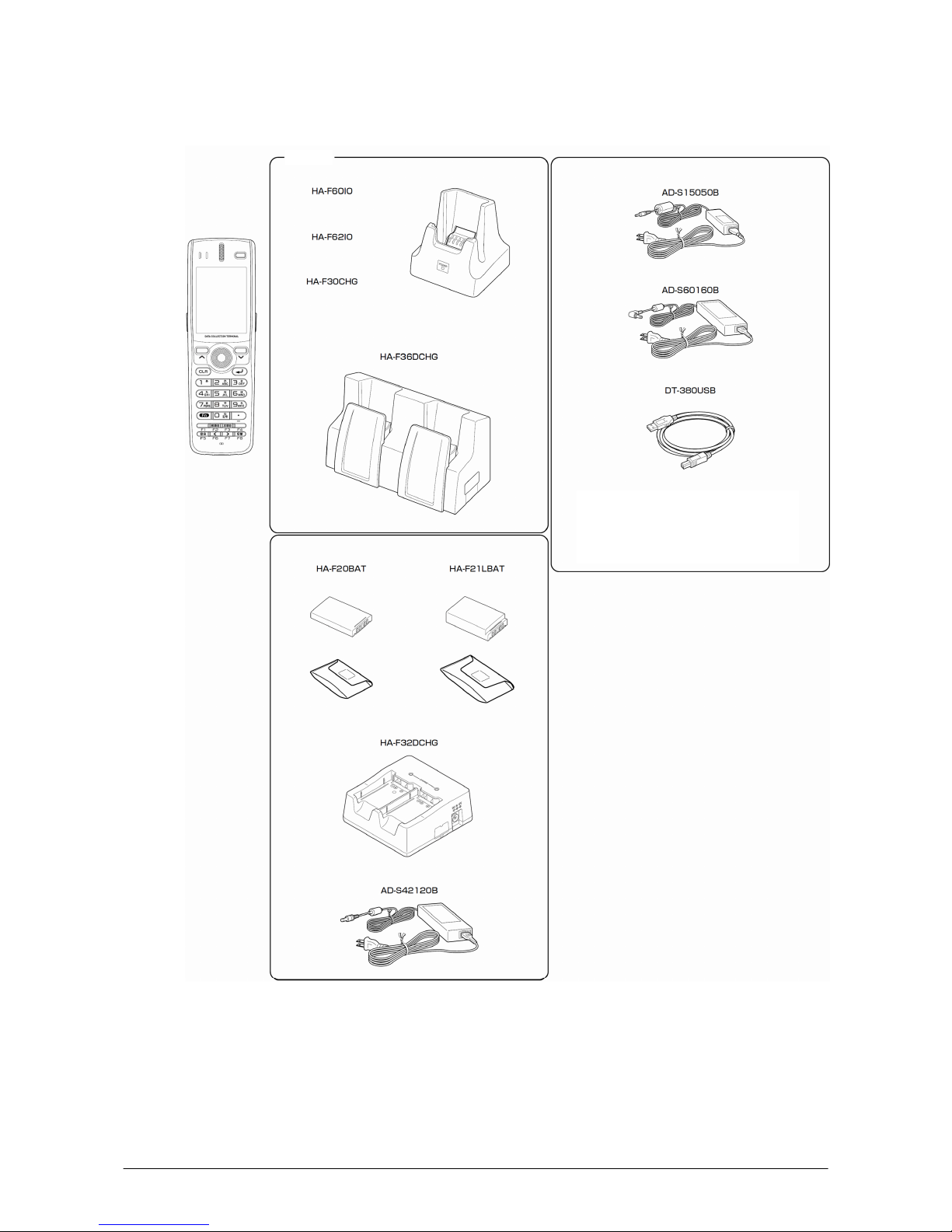
16
External views of the DT-X7 and the dedicated options
Figure 2.1
Option
Page 17

17
2.3 Software Required
PC Operating System
• Microsoft Windows 2000 Professional Service Pack 4 or later
• Or Microsoft Windows 2000 Server Service Pack 4 or later
• Or Microsoft Windows XP Professional Service Pack 2 or later
• Or Microsoft Windows 2003 Server Service Pack 1 or later
• Or Microsoft Windows Vista (Business / Ultimate )
• Or Microsoft Windows 7
• Or Microsoft Windows Server 2008
The following software tools and libraries
are required in order to develop application software for the
DT-X7. Ensure that you download or purchase the correct Microsoft tools as appropriate.
C / C++
• Microsoft Visual Studio 2008 (not free of charge)
• Microsoft Visual Studio 2005 (not free of charge)
• Microsoft eMbedded Visual C++ 4.0
Download for free from;
http://www.Microsoft.com/downloads/details.asp
x?displaylang=en&FamilyID=1DACDB3D-50D
1-41B2-A107-FA75AE960856
• Microsoft eMbedded Visual C++ 4.0 SP4
Download for free from;
http://www.microsoft.com/downloads
/details.aspx?familyid=4A4ED1F4-91D3-4DBE-986E-A812
984318E5&displaylang=en
• Microsoft ActiveSync 4.2 (or later)
Download for free from;
http://www.microsoft.com/downloads
/details.aspx?FamilyID=7269173a-28bf-4cac-a682-58d3233
efb4c&DisplayLang=en
• Microsoft Windows Mobile Device Center 6.1 (for Windows Vista)
Download for free from;
http://www.microsoft.com/downloads
/details.aspx?familyid=46F72DF1-E46A-4A5F-A791-09F0
7AAA1914&displaylang=en
Visual Basic / Visual C#
• Microsoft Visual Studio 2008 (not free of charge)
• Microsoft Visual Studio 2005 (not free of charge)
• Microsoft Visual Studio .NET 2003 (not free of charge)
• Windows CE Utilities for Visual Studio .NET 2003 Add-on Pack 1.1
From Microsoft web site, see
http://www.microsoft.com/downloads/details.asp
x?familyid=7ec99ca6-2095-4086-b0cc-7c6c39b2
8762&displaylang=en
• Microsoft ActiveSync 4.2 (or later)
Download for free from;
http://www.microsoft.com/downloads
/details.aspx?FamilyID=7269173a-28bf-4cac-a682-58d3233
efb4c&DisplayLang=en
• Microsoft Windows Mobile Device Center 6.1 (for Windows Vista)
Download for free from;
Page 18

18
http://www.microsoft.com/downloads/details.aspx?familyid=46F72DF1-E46A-4A5F-A791-09F0
7AAA1914&displaylang=en
CASIO DT-X7 BDK
Download the DT-X7 BDK from
http://www2.casio.co.jp/system_en/pa/PADealer/
(The site requires your user name and password. Enter your user name and password as issued by
CASIO.)
Page 19

19
3. Installing BDK to PC
3.1 Application Development
This chapter explains about what you need to set up for the development environment before starting
your application development.
1. Installing Development Platform
Install Microsoft’s development platform which supports eMbedded Visual C++, Visual Studio
20
08, Visual Studio 2005, and Visual Studio .NET 2003. For detail, refer to Chapter 2.3 "Software
Required".
2. Installing CASIO BDK
Install Casio’s BDK and various libraries if necessary. For installation method, refer to Chapter 3.2
"Installing CASIO BDK Files".
3. Co
nnecting DT-X7 to PC (via ActiveSync/Windows Mobile Device Center)
Connect the DT-X7 to PC via Microsoft’s ActiveSync (for Windows XP or any other OS before
Wind
ows XP) or via Windows Mobile Device Center (for Windows Vista or later). For connection
method, refer to Chapter 5 "Connecting the DT-X7 to PC".
4. Setting Up the Development Environment
Copy all necessary CASIO libraries to the DT-X7.
For detail, refer to Chapter 6 "Setting Up the Development Environment".
5. Installing the Device Emulator
Install the Device Emulator for the DT-X7. Fo
r installation method, refer to Chapter 7 "Device
Emulator". If not necessary to install, go to "6. Application Development" below.
6. Application Development
Now, the application development environment is set up and your development with the
developm
ent platform can be started. After application is developed, transfer it to the Device
Emulator or an actual terminal of the DT-X7 via ActiveSync or Windows Mobile Device Center for
check on the operability. For application development method and transferring your application,
refer to Chapters 8 "eMbedded Visual C++" and Chapter 9 "Visual Studio".
Page 20

20
3.2 Installing CASIO BDK Files
Download the CASIO DT-X7 BDK installation CD image file from the following site and write it to a
CD-ROM media.
http://www2.casio.co.jp/system_en/pa/PADealer/
(The site requires your user name and password. Enter your user name and password as issued by CASIO.)
Notes:
• If you had already installed DT-X7 BDK Ver. 1.xx, be sure to uninstall it before installing Ver. 2.xx.
• If any file of the DT-X7 BBDK Ver. 1.xx remains in the following folders after uninstalling, delete it
m
anually.
C:\Program Files\CASIO\MBSYS
C:\Program Files\Windows CE Tools\wce500
• If your PC runs in the Windows Vista or later OS, first you must disable the User Account Control
("
UAC") by following the process below before installing the CASIO BDK Files.
Case of using Windows Vista and Windows Server 2008
- Navigate to Control Panel → User Accounts → En
able or Disable the User Account
Control. Remove the check on User Account Control (UAC) to protect your PC, and
then click OK button.
Case of using Windows 7
- Navigate to Control Panel → User Accounts → Change User Account Control
Settings. S
elect Never notify in Choose when to be notified about changed to your
computer setting.
Page 21

21
Installing ExportBDK
1. When the CASIO DT-X7 BDK CD-ROM is inserted in the drive of your PC, the following menu
screen appears automatically.
Figure 3.1
2. Click Installation List in
Figure 3.1. The installation screen appears.
Figure 3.2
3. Click DT-X7 ExportBDK
to display the Setup Wizard. Choose any one of the buttons in the screen.
Page 22

22
Installing Library
The DT-X7 Library is available for the below development platforms. The library can be installed for
each development platform in the Installation List screen.
- Microsoft eMbedded Visual C++ 4.0
- Microsoft Visual Studio .NET 2003
- Microsoft Visual Studio 2005
- Microsoft Visual Studio 2008
Notes:
1. The Library header file (*.h) and the Import library
file (*.lib) are installed in the following folder.
C:\Program Files\CASIO\MBS
YS\include : Header file
C:\Program Files\CASIO\MBSYS\lib\ARMV4I : Import library file
2. The Class library DLL file (*.dll) is installed in the following folder.
C:\Program Files\CASIO\MBSYS\WindowsCE
3. When the Library is installed in your PC, the Help file (*.chm) is installed in the following folder.
C:\Program Files\CASIO\MBSYS\HELP
The Help file can be accessed by navigating to Start m
enu → All Programs → CASIO Basic
Development Kit → Help.
Installing Online Help
Besides the Help file described above, the Online Help is also available for the below development
platforms. The installation of the Online Help is initiated in the Installation List for each development
platform.
- Microsoft Visual Studio .NET 2003
- Microsoft Visual Studio 2005
- Microsoft Visual Studio 2008
After the installation is complete, Microsoft Visual Studio starts up. The Online Help file can be
accesse
d by navigating to Help → Contents menu.
Page 23

23
Installing Sample Program
When the Sample is chosen in the Installation List, the sample program folder in the CD-ROM
appears. The Sample program folder is available for each development platform. Copy one of the folders
you wish to use into your PC.
- EVC for Microsoft eMbedded Visual C++
- VS2003 for Microsoft Visual Studio .NET 2003
- VS2005 for Microsoft Visual Studio 2005
- VS2008 for Microsoft Visual Studio 2008
If your sample program is with "Read-only" attribute set
effect. Be sure to disable the attribute before
using it.
Page 24
24
4. Connecting Power Supply to HA-F60IO, HA-F62IO
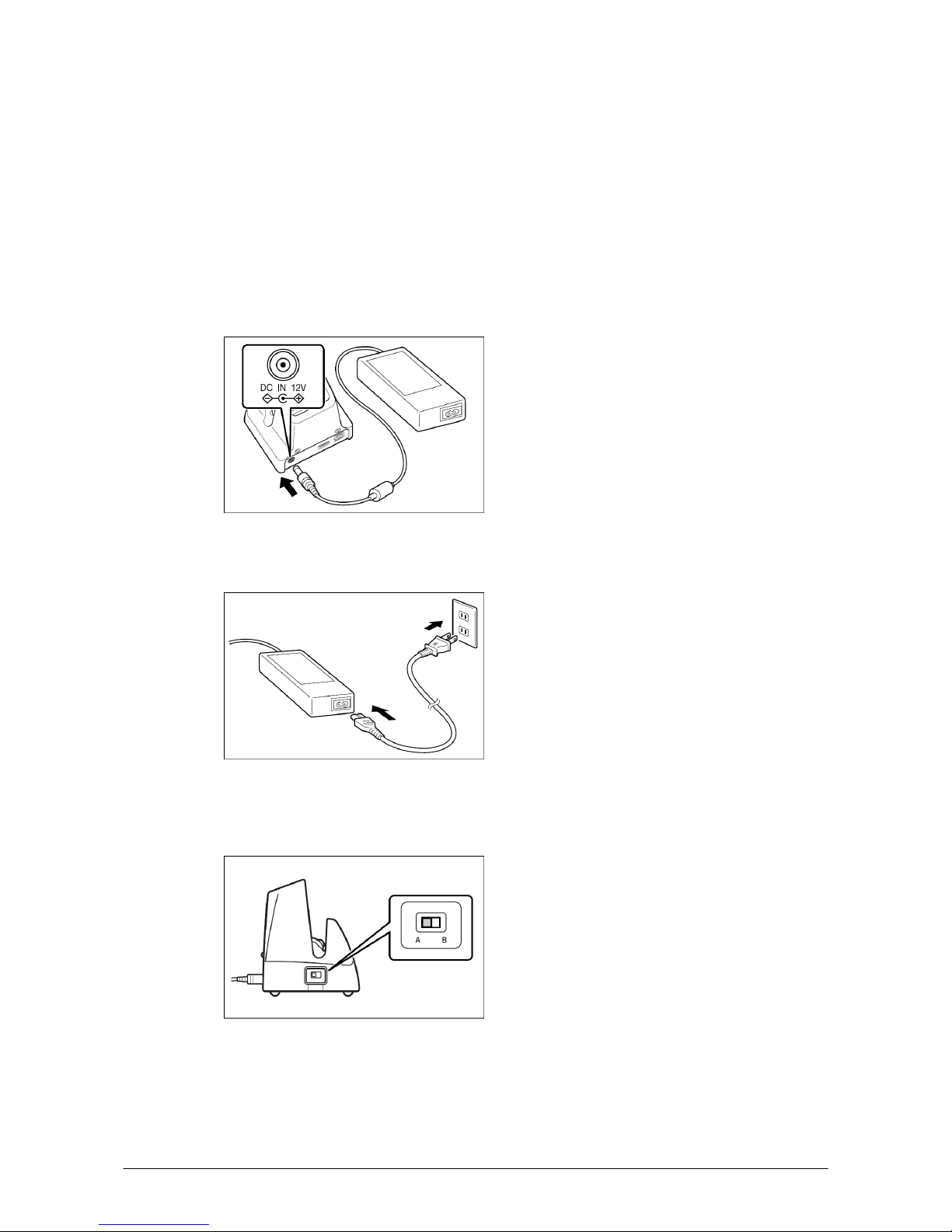
4.1 HA-F60IO
Use the dedicated AC adaptor (AD-S42120B) for supplying power to the HA-F60IO USB Cradle.
Ensure that you connect the AC adaptor to the cradle before starting communication between the DT-X7
and PC via the cradle. Follow the steps below to connect the power supply to the DT-X7 using the
dedicated AC adaptor.
1. Plug the AC adaptor into the AC adaptor jack where "
DCIN12V" is printed on the back of the cradle.
Figure 4.1
2. After connecting the power cable to the AC adaptor, plug in the plug to an electrical outlet.
Figure 4.2
3. Make sure the selector switch on the left side of the cradle is set to position "B" for USB client or
posi
tion A for USB host.
Figure 4.3
Page 25
25
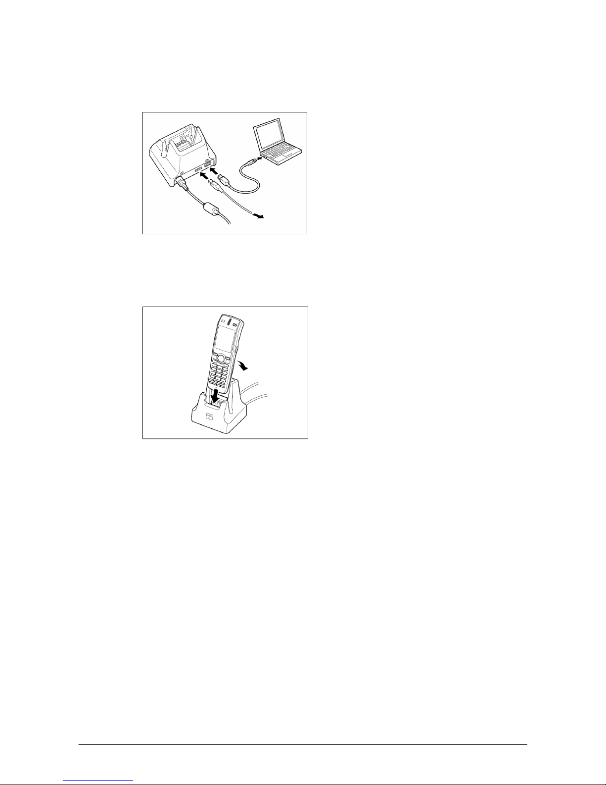
4. Connect a USB cable (DT-380USB) to the USB client port on the back of the cradle, and then
connect the other end of the cable to the PC. USB host port is used when connecting the cradle with
other USB peripheral device.
Figure 4.4
5. Align the USB cradle mount holes on the back of the DT-X7 with the mount hooks on the cradle after
ali
gning the contacts on the bottom of the DT-X7 with the power contacts of the cradle. The power
LED on the front of the cradle will light green if the DT-X7 has been properly mounted.
Figure 4.5
Status of Indicator 1 on DT-X7
Orange : Charging the battery pack.
Red : Standby due to battery pack error or the surround
ing temperature is out of the range (charging
begins when the temperature returns within the correct range.)
Green : Charging the battery pack is complete.
Important n
otes:
• Always remove the DT-X7 from the cradle when switc
hing the selector switch on the cradle.
• Never short the power contacts of the cradle. This damages the cradle.
• Do not subject the DT-X7 and cradle to vibration or impact during communication. This results in
communication being interrupted.
• When mounting the DT-X7, securely attach it to the mount hooks of the cradle and check that the
p
ower LED on the front of the cradle lights green. Charging the battery pack or communication will
not proceed if it is not mounted properly.
Page 26
26
4.2 HA-F62IO
Use the dedicated AC adaptor (AD-S42120B) for supplying power to the HA-F62IO Ethernet Cradle.
Ensure that you connect the AC adaptor to the cradle before starting communication between the DT-X7
and PC via the cradle. Follow the steps below to connect the power supply to the DT-X7 using the
dedicated AC adaptor.
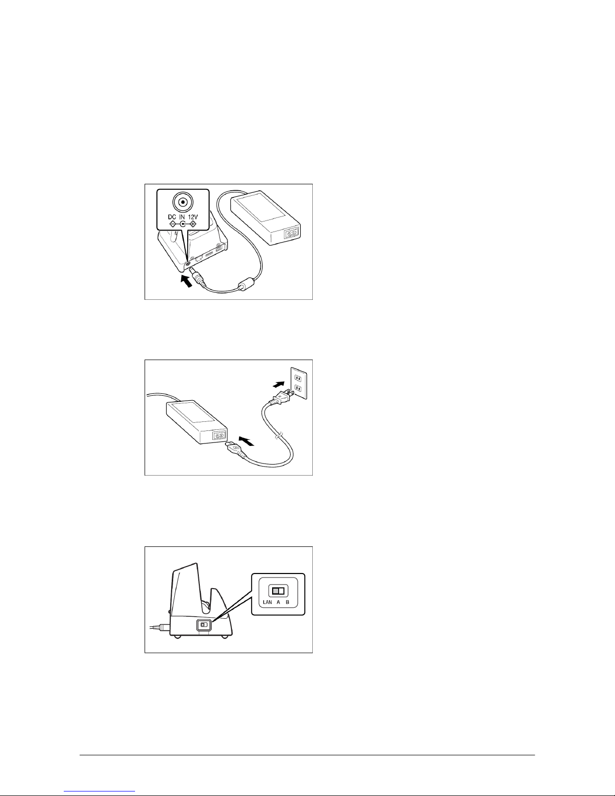
1. Plug the AC adaptor into the AC adaptor jack on the back of the Ethernet Cradle.
Figure 4.6
2. After connecting the AC adaptor to the power cable, plug in the plug of the power cable to an
electrical outlet.
Figure 4.7
3. Set the selector switch on the left side of the Ethernet cradle to the port that will be used. Set the
switch to "LAN" to use the LAN port or to either "A" or "B" to use one of two USB ports. The
position "A" is for USB host, or "B" for USB client.
Figure 4.8
Page 27

27
4. Before using the cradle ports, remove the caps from the ports. When using a LAN, connect one end of
the LAN cable to the LAN port and the other end to the PC or hub. When using a USB connection,
connect one end of the USB cable (DT-380USB) to the USB port and the other end to the PC.
Figure 4.9
5. Align the contacts on the underside of the DT-X7 with the power supply contacts on the Ethernet
Cradle and then set the DT-X7 into the cradle so that mount holes in the back of the DT-X7 are
aligned with the mount hooks on the cradle. Once the DT-X7 is properly set in the cradle, the power
LED on the front of the Ethernet cradle lights green.
Figure 4.10
Status of Indicator 1 on DT-X7
Orange : Charging the battery pack.
Red : Standby due to battery pack error or the surround
ing temperature is out of range (charging
begins when the temperature is within the correct range.)
Green : Charging the battery pack is complete.
Important n
otes:
• Always remove the DT-X7 from the Ethernet Cradle before changing the selector switch setting.
• Never short out the power contacts of the cradle. This damages the cradle.
• Do not subject the DT-X7 and cradle to vibration or impact during communication. This results in
com
munication being interrupted.
• When mounting the DT-X7, securely attach it to the mount hooks of the cradle and check that the
power LED on the front of the cradle lights green. Charging battery pack or communication will not
proceed if it is not mounted properly.
• The LAN and USB connections cannot be used concurrently.
• Always cap ports that are not being used. Using the Et
hernet Cradle while the ports are uncapped can
cause damage.
Page 28

28
5. Connecting the DT-X7 to PC
To make connection establishment with PC, use one of the methods, depending on the OS your PC runs,
described below.
• ActiveSync (f
or Windows XP or any other OS earlier)
Use the ActiveSync to connect the DT-X7 to PC if the PC runs in Windows XP or other OS earlier
than Windows XP. See Chapter 5.1 "ActiveSync Connection via USB" for the us
e of ActiveSync.
The ActiveSync can be downloaded at the URL below.
http://www.microsoft.com/downloads/details.aspx?FamilyID=7269173a-28bf-4cac-a682-58d3233ef
b4c&DisplayLang=en
• Windows Mobile Device Center (for Windows Vista
or later)
Use the Windows Mobile Device Center to connect the DT-X7 to PC if the PC runs in Windows
Vista OS. See
Chapter 5.2 "USB Connection via Windows Mobile Device Center" for the use of
Windows Mobile Device Center. The Windows Mobile Device Center ("WMDC") can be
downloaded at the URL below.
http://www.microsoft.com/downloads
/details.aspx?familyid=46F72DF1-E46A-4A5F-A791-09F07A
AA1914&displaylang=en
Page 29

29
5.1 ActiveSync Connection via USB
In nearly all cases during development work you will be communicating with the DT-X7 via an
ActiveSync connection. There are many ways to connect the DT-X7 to a PC via ActiveSync.
If you have already installed ActiveSync and connected the DT-X7 to the PC via direct USB, You may
skip
Chapter 5.1.1 "Installing ActiveSync for the First Time". You already have the USB driver and
ActiveSync in your development environment. If you do not yet have the cradle driver on your PC,
download the USB driver files "wceusbsh.inf" and "wceusbsh.sys" from the CASIO Web Site and copy
them to an appropriate folder.
5.1.1 Installing ActiveSync for the First Time
1. Install ActiveSync first. Run the ActiveSync ‘msi’ file.
Figure 5.1
2. Click I
nstall button.
Figure 5.2
Page 30

30
3. Pause the installation when the menu in Figure 5.3 is displayed; you have to install the driver at this
point.
Figure 5.3
4. Connect the USB cable to the PC and the other end to t
he USB Cradle and also the AC adaptor to the
USB Cradle.
5. Put the DT-X7 on the cradle and confirm that the green LED on the front of the cradle is lit. If not, be
sure t
he DT-X7 is positioned firmly on the cradle.
6. When the DT-X7 is mounted on the USB Cradle, a dialog is displayed to prompt you to install the
su
itable driver. If you have not yet obtained the driver files, see page 23 for details of what you need
to download.
7. Choose No, not this t
ime radio button in Figure 5.4 and then click Next > button.
Figure 5.4
Page 31

31
8. Then, choose Install from
a list or specific location [Advanced] radio button in the menu.
Figure 5.5
9. Click N
ext > button.
Figure 5.6
Page 32

32
10. Choose Windo
ws CE USB Devices icon.
Figure 5.7
11. Click H
ave Disk… button.
Figure 5.8
12. Click B
rowse… button. Choose "wceusbsh.inf" from the folder you created in step 6.
Figure 5.9
Page 33

33
13. The installation of the driver will start.
Figure 5.10
14. Click C
ontinue Anyway button.
Figure 5.11
15. A menu might be displayed to prompt you to install "wceusbsh.sys". This happens if "wceusbsh.sys"
is n
ot in the same folder as "wceusbsh.inf". Download this file from the CASIO Web Site and follow
the prompts to specify the location of "wceusbsh.sys".
Page 34

34
16. Now the installation of the driver is finished.
Figure 5.12
17. Now go back to the ActiveSync Installation Wizard that you left on the desktop. Click N
ext > button.
Figure 5.13
Page 35

35
18. Now the connection is established. You can choose either partnership option according to your needs.
Then click N
ext > button.
Figure 5.14
19. Now the connection is completed. You can start up eMbedded VC++ or Visual Studio and create a
program and deploy it to the DT-X7.
Figure 5.15
Notes:
• When you change the setting of the USB interface usi
ng the switch on the HA-F60IO USB Cradle,
be sure to take the DT-X7 out of the cradle first.
• Never short-circuit the pins of the cradle. Shorting the pins will cause serious damage to the cradle.
• Do not vibrate or knock the cradle or the DT-X7 while communicating. Any vibration might cause
disc
onnection of communication.
Page 36

36
5.1.2 If ActiveSync Is Already Installed
This is the procedure if ActiveSync is already installed on the PC. You just need to let the PC recognize
the DT-X7 and install the cradle driver as in steps 6 to 16 in Chapter 5.1.1"Installing ActiveSync for the
First Time".
1. Choose F
ile → Connection Settings…. from the menu in ActiveSync. See Figure 5.16.
Figure 5.16
2. Check Allo
w USB connection with this desktop computer. USB is available.
Figure 5.17
Page 37

37
3. On the DT-X7, in Control Panel, choos
e the PC Connection option. Confirm that PC Connection
is set to "USB Default". If not, choose ‘USB Default’ and tap OK button.
Figure 5.18
4. When the DT-X7 is mounted on the USB Cradle, a menu to prompt to install the driver is displayed.
Follow
the same steps in Chapter 5.1.1 "Installing ActiveSync for the First Time".
Figure 5.19
Page 38

38
5.2 USB Connection via Windows Mobile Device Center
To establish connection via USB interface with PC runs in Windows Vista, use Windows Mobile Device
Center ("WMDC"). The DT-X7 with the factory-setting (default) does not support the WMDC. Follow
the procedure below to change the setting on the DT-X7.
Note that the CAB file, USBClientDTX7E.110.CAB,
must be installed in the DT-X7 prior to
establishing connection with the DT-X7 via Windows Mobile Device Center. For installation method,
refer to Chapter 6.1 "Installing CAB Files".
Procedure
1. Close all applications running on the DT-X7.
2. Navigate to Settings → Control Panel → USB Connection.
3. Click Conne
ct Utility tab.
Figure 5.20
4. Choose Windo
ws Mobile Device Center radio button and then click OK button.
Figure 5.21
5. A dialogue asking your final confirmation appears. Click Y
ES button.
Figure 5.22
Page 39

39
6. The DT-X7 starts up again.
7. Mount the DT-X7 on the cradle, and then follow a m
essage appeared in the WMDC on the PC.
Notes:
• To resume the factory default setting, choose ActiveS
ync/LMWIN radio button in Step 3 on the
previous page, and start up the DT-X7 again.
• The WMDC version 6.1 or later will support the connection establishment via USB interface. Any
other versions of the WMDC earlier are not interoperable with Windows CE devices.
Page 40

40
5.3 Connection via IrDA
If the PC has an IrDA interface, it is possible to connect the DT-X7 to the PC via IrDA using
ActiveSync.
Follow the steps below to establish connection via IrDA:
1. Choose PC Connection in
the Control Panel on the DT-X7.
2. Set PC Connection to IrDA.
3. Set the COM port used by ActiveSync on the PC to Infrared Port(IR).
4. Place the IrDA port located on the bottom of t
he DT-X7 facing the IrDA port on the PC.
Communication can be established if the distance is between zero and approximately 1 m. In the
case of 4Mbps rate, the maximum distance is approximately 30 cm.
5. On the DT-X7, from Start
menu, navigate to Programs → Communication → ActiveSync
to start up ActiveSync.
Page 41

41
5.4 Connection via Bluetooth
To establish communication between DT-X7 and PC via Bluetooth configuration, follow the steps, 1 to
4, below to set up a Bluetooth configuration on the DT-X7. Note that all the models of DT-X7 series
integrate the Bluetooth module.
1. Navigate to Start m
enu → Settings → Control Panel → Bluetooth Connection icon.
2. Click and hold the Serial
Port Profile icon to display the context menu (see Figure 5.23), and
highlight Use to connect for ActiveSync in the menu. The icon changes to the
icon
(ActiveSync). See Figure 5.24.
Figure 5.23 Figure 5.24
3. Double click the icon establishes connection via ActiveSync in Serial Port Profile. If Serial Port
Profile is
not used, click and hold the icon, and then highlight Do not use for ActiveSync
connection.
4. Click the icon in the Toolbar to close the communication. To close the Bluetooth connection
screen, click the icon in the Toolbar.
Note:
When establishing connection with PC via ActiveSync, set a virtual COM port to the same COM port
num
ber in the ActiveSync setting that uses Bluetooth Serial Port Profile.
Page 42

42
5.5 Connection via WLAN
To establish communication between the DT-X7 and PC via WLAN configuration, follow the steps, 1 to
6, below to set up a WLAN configuration on the DT-X7. After setting up the configuration, be sure to
perform a site survey prior to starting communication via WLAN.
1. Navigate to Start → Settings → WLANConfig and
then click IP tab.
Figure 5.25
Table 5.1
Parameter Description
Enable DHCP or Configure IP Determines "Enable" or "Disable" for DHCP.
IP Determines IP address.
MASK Determines subnet mask.
GateWay Determines default gateway.
DNS1 Determines primary DNS address.
DNS2 Determines secondary DNS address.
WINS1 Determines primary WINS address.
WINS2 Determines secondary WINS address.
2. If any of the settings in Figure 5.25 is omitted, the process described in the following table will
automatically take effect in the field.
Table 5.2
Para
meter Nothing is set (DHCP) "Configure IP" is set
Enable DHCP or
Configure IP
"Enable DHCP" is assumed. "Configure IP" is set.
IP Does not determine IP address. Entered address is set as is.
MASK Does not determine subnet mask. Entered address is set as is.
GateWay Does not determine gateway. Entered address is set as is.
DNS1 Does not determine primary DNS
address.
Entered address is set as is.
DNS2 Does not determine secondary DNS
address.
Entered address is set as is.
WINS1 Does not determine primary WINS
address.
Entered address is set as is.
WINS2 Does not determine secondary WINS
address.
Entered address is set as is.
Page 43

43
3. Click Basic t
ab. Set each parameter in the tab by referring to the descriptions for the parameters
in Table 5.3 and Table 5.4.
Figure 5.26
Table 5.3
Parameter Description
SSID Enter the SSID of the network you want to connect to.
Security Disable None.
WEP Open in Authentication field.
WPA
WPA2
(note)
PSK in Authentication field (if selected, the Key field must be set also.)
EAP-PEAP in
Authentication field
EAP-TLS
in Authentication field
Key Enter 26 (maximum) alphanumeric digits (13 hex pairs) in the Key field if 128 bit
radio button is selected. Or, enter 10 (maximum) alphanumeric digits (5 hex pairs) in
the Key field if 64 bit radio button is selected.
The field displays the number of characters that have been entered.
***** in the field implies that the key has been extracted from the ini file. If ***** in
the field is edited, a new key has been deemed to be set. Or, if it has never been edited,
the key extracted from the ini file becomes effective as is.
Note:
WPA2 is available on DT-X7M10R2, M50R, M10R2-CN, M30R, and M30R-CN.
Page 44

44
4. If EAP-PEAP radi
o button in Authentication field is selected, click the EAP-Properties button that
appears when selecting the EAP-PEAP radio button to set also the following parameters.
Table 5.4
Parameters in
EAP-Proper
ties screen
Description Default
User name Input a user name in alphanumeric (maximum 100
alphanumeric).
None
Password Input a password in alphanumeric (maximum 100
alphanumeric).
***** in the field implies that the password has been
ext
racted from the ini file. If ***** in the field is
edited, a new password has been deemed to be set.
Or, if it has never been edited, the password extracted
from the ini file becomes effective as is.
None
Domain Input a domain in alphanumeric (maximum 100
alphanumeric).
None
Validate server
certificate
Set up the requisition for server certificate.
With checkmark : certificate is required.
Without checkmark: certificate is not required.
Certificate is not necessary
5. If EAP-TLS radi
o button in Authentication field is selected, click the EAP-Properties button that
appears when selecting the EAP-TLS radio button to set the following settings.
Table 5.5
Parameters in
EAP-Proper
ties screen
Description Default
User name Input a user name in alphanumeric (maximum
100 alphanumeric).
None
Certificate Select a client certificate installed already
(maximum 100 alphanumeric).
Search bu
tton in the field will display a list of
installed client certificates. Select one by
highlighting it.
None
Domain Input in alphanumeric (maximum 100
alphanumeric)
None
Validate server
certificate
Set up the requisition for server certificate.
With checkmark : certificate is required.
Without checkmark : certificate is not required.
Certificate is required.
Page 45

45
6. Click WLAN tab.
Figure 5.27
Table 5.6
Field / Radio
B
uttons
Description Default
Adapter power On Enable power to the integrated WLAN module. Yes
Off Disable power to the integrated WLAN module.
Power save Enable Enable power save mode for the WLAN module. Yes
Disable Disable power save mode for the WLAN module.
Standard b Set up IEEE802.11b standard effect.
b/g Set up IEEE802.11b/g standard effect. Yes
RSSI Level for
initiating roaming
No roaming Set up "-100 dBm" for roaming starting threshold level,
a level where communication via WLAN is practically
impossible, so that roaming should not be carried out.
Default Set up "-78 dBm" for the roaming starting threshold
level.
Yes
High Set up "-72 dBm" for roaming starting threshold level,
for faster (more frequent) roaming
7. Click Detail ta
b.
Figure 5.28
Page 46

46
Table 5.7
Field / Radio Buttons Description Default
WLAN configure /
Status display tool
WLANConfig
/
NetSearch
- Use only CASIO provided WLAN tool.
- Configure WLAN setting with settings
extracted from the ini file.
- Initiate NetSearch when tapping the icon in
th
e task tray.
Yes
WLANConfig /
NetUI
- Use both CASIO provided WLAN tool and
MS tool.
- Configure WLAN setting with settings
e
xtracted from the ini file.
- Initiate NetUI (MS tool) when tapping the
i
con in the task tray.
NetUI / NetUI - Use only the MS tool.
- Configure WLAN setting, not with settings
e
xtracted from the ini file.
- Initiate NetUI when tapping the icon in the
ta
sk tray.
If this radio button is selected and the OK bu
tton
that appears in the subsequent popup warning
message is clicked, other settings in the ini file
will be deleted. Only the WLAN configuration
set with NetUI is saved.
Enable adhoc network setting With checkmark : enable the setting.
Without checkmark : disable the setting. Yes
Enable all authentication settings With checkmark : enable the setting.
Without checkmark : disable the setting. Yes
Inifile comment Enter a comment of up to 100 characters to be
written in the ini file.
None
8. If OK butt
on in the popup warning message (see Table 5.7 for description of NetUI/NetUI radio
button) is clicked, the screen in Figure 5.29 appears. Click OK button to perform a reset on the
terminal so that the setting takes effect.
Figure 5.29
9. Check to make sure that the connection has been established using the NetSear
ch utility, and then
navigating to the Ping function in there. Enter HostName first and then click Ping to check that you
are connected to the network correctly.
Page 47

47
5.6 Connection via Ethernet Cradle
This chapter describes how to establish a high speed LAN connection on the WLAN non-integrated
models with HA-F62IO Ethernet cradle via ActiveSync 3.8 (see note) or earlier.
Note:
Later versions of the Microsoft ActiveSync do not sup
port this connection. Use version 3.8 or earlier to
establish the connection.
Follow the steps below:
1. Establish partnership first between the DT-X7 and PC using any method so far described in this guide
(con
nection establishment via IrDA, WLAN, Bluetooth or USB cradle).
2. Connect the dedicated AC adapter to the Ethernet cradle as described in Chapter 4.2.
3. Connect one end of the network cable to the Ethernet cradle and the other end to the network hub.
4. Make sure the selector switch on the left side of the HA-F62IO Ethernet cradle is set to the "LAN"
posi
tion. See Figure 5.30 below.
Set to LAN
Figure 5.30
5. Place the DT-X7 in the cradle and navigate to Start → S
ettings → Control Panel → Network
and Dial-up Connections.
6. The following screen will appear. D
ouble click the AX887721 icon. The icon will not appear unless
the terminal is seated in the cradle.
Figure 5.31
Page 48

48
7. The following TCP/IP screen appears. Set all the parameters in IP
Address and Name Servers
tabs as required and click OK button.
Figure 5.32
8. If the connection is established correctly, the icon ( ) in the taskbar changes to ( ).
9. On the PC, make sure that Allo
w network… checkbox is checked in the ActiveSync setting.
10. On the DT-X7, navigate to Start → P
rograms → Communication → LAN ActiveSync to
initiate the connection. Make sure in the popup ActiveSync menu box that Network Connection is
the selected connection method and Connect to: field is the name of your PC. Click Connect …
button and then the connection should be established.
Page 49

49
5.7 Accessing Shared Network Drive on Your LAN
Assuming you have a valid network connection established, you can access shared drives on your PC
from the File Explorer on the DT-X7. The following shows the steps to initiate this.
1. Configure a network connection on the DT-X7.
2. Double click My Computer.
3. Type \\xxxx\ where xxxx is the network name of the PC.
4. A network logon dialog box will appear. Enter a
valid User ID, Password and Network Domain.
5. Any shared network drives on the target PC will be displayed and you will be able to copy files
freely between them and the DT-X7.
Page 50

50
5.8 Direct TCP/IP Connection from Visual Studio
If you have a network connection to the DT-X7 (for example, via WLAN or the Ethernet cradle) then
you can establish a direct link to the development PC without using ActiveSync.
For Visual Studio .NET 2003
If network connection has been established between the DT-X7 and the PC that is under the application
dev
elopment environment, the WindowsCE Utilities add-on pack (described in Chapter 2.3) can be used
to m
ake direct link possible. Refer to the readme file supplied with the add-on pack for detail on how to
set up the connection.
For Visual Studio 2005
1. Download the files listed below from the PC running in Visual Studio 2005 to the DT-X7.
- Clientshutdown.exe
- ConmanClient2.exe
- CMAccept.exe
- DeviceDMA.dll
- eDbgTL.dll
- TcpConnectionA.dll
The source folder in the PC:
C:\Program Files\Common Files\Microsoft Shared\C
oreCon\1.0\Target\wce400\armv4i
The destination folder in the DT-X7:
\Windows
2. Run Conma
nClient2.exe on the DT-X7.
3. Set the device IP address in Visual Studio 2005.
4. Navigate to T
ools in the main menu of Visual Studio 2005 → Options… → Device Tools →
Devices.
5. Choose DT-X7 Device in t
he pull-down menu of Devices: and click Properties….
6. Click Transport: to access Configure… and set up Device IP address as shown in Figure 5.33.
Figure 5.33
7. Run CMAccept.exe on the DT-X7.
8. Navigate to T
ools in the main menu of Visual Studio 2005 → Connect to Device….
Page 51

51
9. Choose DT-X7 Device i
n the list of Devices: and click Connect button. The screen in Figure 5.34
if appear indicates the success of connection establishment.
Figure 5.34
Page 52

52
6. Setting Up the Development Environment
6.1 Installing CAB Files
1. After installing the library files, the CAB files in Table 6.1 will be installed in the folder below.
C:\Program Files\CASIO\MBSYS\CAB
Table 6.1
Library CAB file Preinstalled
System Library en_SystemLib.ARMV4I.CAB Yes
Laser Scanner Library en_OBReadLib.ARMV4I.CAB Yes
Imager Library en_ImagerLib.ARMV4I.CAB Yes
Bluetooth Library en_BluetoothLib.ARMV4I.CAB Yes
JPEG library en_JPEG.ARMV4I.CAB Yes
FLINK library en_Flink.ARMV4I.CAB Yes (note 2)
Notes:
1. The library with "Yes" in "Preinstalled" column is preinstalled in the DT-X7 and in the Device
Emulator. Thus, it is not necessary to install it, unless it has been updated or changed.
2. The CAB file, en_Flink.ARMV4I.CAB, in the table does not operate for the DT-X7. Use the
Flink
Lib.dll installed by default in the terminal.
Download the CAB file in
2. Tabl
e 6.2 from the following site.
http://www2.casio.co.jp/system_en/pa/PADealer/
(The site requires your user name and password. Enter your user name and password as issued by
CASIO.)
Table 6.2
CAB file Description
USBClientDTX7.110.CAB USB client supported by Windows Mobile Device Center
Copy all the CAB files in Table 6.1 and
3. Table 6.2 to any folder on the DT-X7 via ActiveSync.
4. Carry out each CAB file.
5. When the installation starts, the installation status will appear.
Page 53

53
6.2 eMbedded Visual C++ 4.0
ExportBDK for DT-X7 is required to develop application software in eMbedded Visual C++ 4.0 (see
note 1). Follow the steps below to install it.
1. Double click the DT-X7_BDK.msi (see
note 2) file and follow the prompts that appear on the screen
to install the BDK.
2. When prompted whether you want to install Custom or Complete instal
lation, choose Complete.
3. When the installation is finished, start
up eMbedded Visual C++ 4.0.
4. Go to Chapter 8 "eMbedded Visual C++" and follow the instructions to verify that the BDK has been
installed correctly.
If eMbedded Visual C++ has been installed in your PC already, you will notice that you now have a new
BD
K and, once you choose that new BDK, a new target device (DT-X7) in the comb-box menu in the
Toolbar. Also, if you use any of the Remote Tools in eVC++ then you will find DT-X7 is listed as a new
target (for example, try the Remote Registry Editor).
For more detail, refer to Chapter 8 "eMbedded Visual C++".
Notes:
1. If eMbedded Visual C++ 4.0 is used to develop application software, be sure to install Service Pack 4
prior t
o the development.
2. Other BDKs (e.g. standard BDK etc.) released before the ExportBDK are als
o operable.
3. Application software developed using MFC (Microsoft Foundation Class) for CASIO IT-10 is not
opera
ble on the DT-X7.
4. Any application developed not using MFC is operable on the DT-X7.
Page 54

54
6.3 Visual Studio 2005
Follow the steps in Chapter 5 "Connecting the DT-X7 to PC" before checking the steps below to confirm
that you can connect to the DT-X7 from Visual Studio 2005.
1. Establish connection with the DT-X7 via ActiveSync.
2. Open the application project for VB or C# in Visual Studio 2005.
3. Click the button shown in the red box below (see Figure 6.1) to make sure that Visual Studio 2005
has rec
ognized the connection established with the DT-X7 via ActiveSync. If it does not, start up
ActiveSync again to establish connection.
Figure 6.1
4. Choose DT-X7 Device in
the pull-down menu box in Figure 6.2.
Figure 6.2
5. You will now be able to deploy solutions and also debug application software while observing actual
m
ovement of the application running on the DT-X7 using the Visual Studio 2005 debugging features.
Page 55

55
6.4 Visual Studio .NET 2003
Follow the steps in Chapter 5 "Connecting the DT-X7 to PC" before checking the steps below to confirm
that you can connect to the DT-X7 from Visual Studio .NET 2003. Microsoft has released an add-on for
Visual Studio .NET 2003 that allows you to set the target CPU for a connected device (Visual Studio is
unable to detect the target CPU of non-Pocket PC devices).
Follow the steps below to install the add-on pack.
1. Download "Windows CE Utilities for Visual Studio .NE
T 2003 Add-on Pack 1.1" from the site
described in Chapter 2.3 "Software Required".
2. Establish connection via A
ctiveSync between the DT-X7 and PC using any of the methods
described in this guide.
3. Start up Visual Studio .NET 2003 and navigate to Tools → Select Windows CE Device CPU. In
this case, an error message appears if the connection via ActiveSync has not been established.
4. In S
elect the device architecture pull-down menu box, choose ARMV4I, and then click
Configure and Close buttons.
5. Start up Visual Studio .NET 2003 again.
You will now, for example, be able to choose Deplo
y <appname> from the Build menu and your
project will be directly deployed to the DT-X7. You will also be able to remotely debug applications
over your ActiveSync connection.
Page 56

56
7. Device Emulator
The Device Emulator provides application developers with an environment that, without having the
actual device available, allows them to debug basic functions and performance of an application at
source level by stepping through the source code.
7.1 Software Required
The Device Emulator requires the software(s) listed below before installing the emulator.
Using Visual Studio 2008 or Visual Studio 2005
• ActiveSync 4.2 or a later version (If required)
http://www.microsoft.com/downloads
/details.aspx?FamilyID=7269173a-28bf-4cac-a682-58d3233efb
4c&DisplayLang=en
• Visual Studio 2008 or Visual Studio 2005 (Required)
• CASIO DT-X7 BDK (Required)
• Microsoft Device Emulator 3.0 (Optional)
http://www.microsoft.com/downloads/details.aspx?
displaylang=en&FamilyID=a6f6adaf-12e3-4b2f
-a394-356e2c2fb114
See "Microsoft Device Emulator 3.0" described in the next page.
Using Visual Studio .NET 2003
• ActiveSync 4.2 or a later version (If required)
http://www.microsoft.com/downloads/details.aspx?FamilyID=7269173a-28bf-4cac-a682-58d3233
efb4c&DisplayLang=en
• Microsoft Device Em
ulator 3.0 (If required. See "Microsoft Device Emulator 3.0".)
http://www.microsoft.com/downloads/details.aspx?
displaylang=en&FamilyID=a6f6adaf-12e3-4b2f
-a394-356e2c2fb114
• Visual Studio .NET 2003 (Required)
• CASIO DT-X7 BDK (Required)
Using eMbedded Visual C++ 4.0
• ActiveSync 4.2 or a later version (Required)
http://www.microsoft.com/downloads
/details.aspx?FamilyID=7269173a-28bf-4cac-a682-58d3233ef
b4c&DisplayLang=en
• Microsoft Device Emulator 3.0 (If required. See note and "Microsoft Device Emulator 3.0".)
http://www.microsoft.com/downloads/details.aspx?
displaylang=en&FamilyID=a6f6adaf-12e3-4b2f
-a394-356e2c2fb114
• Microsoft eMbedded Visual C++ 4.0 (Required)
http://www.Microsoft.com/downloads/details.asp
x?displaylang=en&FamilyID=1DACDB3D-50D1-
41B2-A107-FA75AE960856
• Microsoft eMbedded Visual C++ 4.0 ServicePack4 (Required)
http://www.microsoft.com/downloads
/details.aspx?familyid=4A4ED1F4-91D3-4DBE-986E-A8129
84318E5&displaylang=en
• CASIO DT-X7 BDK (Required)
Page 57

57
Note:
The software is not required
if your PC has already Visual Studio 2005 installed.
Microsoft Device Emulator 3.0
Follow the steps below to use Microsoft Device Emulator 3.0.
• Install DT-X7 ExportBDK and Device Emulator from the DT-X7 BDK into your PC.
• Download the Microsoft Device Emulator 3.0 and install it in the PC.
• Edit the following file and save the change made.
C:\Program Files\Windows CE Tools\wc
e500\DT-X7\Emulation\DT-X7.cdes
Before you change, the default
parameter in the file is described as follows.
module=DevEmu500.exe
Change the parameter to the one below. Be sure to describe the whole parameter in single one line.
module=C:\Program Files\Microsoft Device
Emulator\1.0\DeviceEmulator.exe
You can substitute the Device Emulator Version 3.0 released in Visual Studio 2008 for an engine of
Device Emulator included in the DT-X7 BDK by the mentioned procedure above.
Page 58

58
Case of using after Windows Vista OS
If you use OS after Windows Vista (Windows 7 or Windows Server 2008), please set device emulation
and I/O simulator as administrator.
Please check "Run this program as an administrator" of property from opening Explorer.
(Ex. Execute I/O simulator in Windows Vista as administrator.)
Figure 7.1
These program have installed the following location as default setting.
• Device emulator
C:\Program Files\Microsoft Device Em
ulator\1.0\DeviceEmulator.exe
• I/O simulator
C:\Program Files\Common Files\CA
SIO\Emulator\DevIoSim.exe
Page 59

59
7.2 Starting Up the Device Emulator
After installing all required software described in Chapter 7.1, follow the steps below to start up the
Device Emulator on your PC.
1. Navigate to Start m
enu → All Programs → CASIO Device Emulator and click DT-X7.
2. Make sure that the DT-X7 Device Emulator has st
arted up on the screen. See Figure 7.1.
3. Navigate to Start m
enu → All Programs → CASIO Device IO Simulator and click IO
Simulator.
4. Make sure that the IO
Simulator has started up on the screen. See Figure 7.2.
5. If Figure 7.1 and Figure 7.2 appear on your PC, you are ready to use the emulator.
Note.
If do not appear "DT-X7" in
"CASIO Device Emulator", please execute "Add Device".
If you use OS after Windows Vista, please execute "DevEmuLoader.exe" as administrator by referring
"Case of
using after Windows Vista OS" section.
C:\Program Files\Common Files\CASIO
\Emulator\DevEmuLoader.exe
Figure 7.2 DT-X7 Device Emulator Figure 7.3 I/O Simulator
Terminology of Emu
lator and Simulator;
The Emulator described in this reference manual is a software application that behaves in a very
similar way to the actual device by imitating individual hardware components or protocols present in the
actual hardware.
On the other hand, the Simulator is als
o a software application that logically integrates application
programming interfaces ("API") and certain other functions to allow debugging of the application
Page 60

60
program using external events. The Emulator performs in a pseudo CPU and hardware environment
and it is impossible for the application to recognize whether it is in the actual device environment or
pseudo environment. However, actions carried out by the Simulator are not as alike to those performed
by actual components but merely mimic them very closely.
Page 61

61
7.3 Using the Device Emulator
7.3.1 DT-X7 Device Emulator
The DT-X7 Device Emulator emulates various operations carried out by the actual DT-X7 device on
the PC’s screen such as mouse operation, input on PC’s keyboard, displaying execution of applications,
and operations by actual devices such as the scanner. Figure 7.3 shows an emulated DT-X7 device on
the s
creen of a PC.
The emulator does not have the capability to save the condition at a time of closing the emulator causing
the
emulator’s clock and file system to be initialized every time when it starts up.
Figure 7.4
Key Input
The emulator offers key input capability similar to that of the actual DT-X7 device. For instance, a key
on the emulated keyboard of DT-X7 on the screen (see Figure 7.3) can be clicked with the PC mouse as
wel
l as key input made directly on the PC’s keyboard.
Reading Bar Codes
The emulator enables bar codes pre-registered in the I/O Simulator (see Figure 7.2) to be input when
clicking Trigger key on the emulated keyboard (see Figure 7.3). Note however that the Trigger key must
be continuously pressed for a second or more otherwise an incorrect key input may result.
Sound
The emulator offers beep and sound capability similar to that of the actual DT-X7 device.
Page 62

62
7.3.2 I/O Simulator
The I/O Simulator simulates registration of bar codes, generation of low battery warning, detection of
terminal being mounted on cradle.
Registration of bar code symbologies
1. Registration
Click ADD1D or ADD2D
button (circled in red in Figure 7.4) to go into the bar code registration
mode.
Figure 7.5
2. Bar code registration
Choose a bar code symbology in the Code T
ype pull-down menu that you wish to register in the
I/O Simulator.
Figure 7.6
Page 63

63
3. Registration of bar code and note
Enter bar code data in the C
ode field (see Figure 7.6) and a note about the bar code in the Note
field if necessary. Click OK button to complete the bar code registration.
Figure 7.7
4. Completion of registration
After completion of the bar codes registration, the screen in Figure 7.7 shows a list of bar codes that
have been regi
stered in the I/O Simulator. Prior to debugging with the Device Emulator, make
sure that you register all bar codes you wish to use in debugging.
Figure 7.8
Note:
In the DT-X7 Device Emulator, types of bar code symbology can be registered are limited to ones which
are set
effect for reading. At a time of starting up the emulator, all the types of bar code symbology are set
readable by default. However, readable bar code symbologies in debugging application software are
defined by the setting of the application software to be debugged.
Page 64

64
5. Editing registered bar code content
Highlight a bar code in the list of registered bar codes (see Figure 7.7) and click Edit bu
tton. Figure
7.8 appears for editing the bar code and its information.
Figure 7.9
6. Deleting registered bar code content
Highlight a bar code in the list of registered bar codes (see Figure 7.7) and click the Del but
ton.
Dialogue screen in Figure 7.9 appears for you to confirm the deletion. If it is okay to delete, click
Yes button, otherwise click No button.
Figure 7.10
Page 65

65
Detection of Terminal in Cradle and Low Battery Warning
If you check the I/O Box and Low Battery boxes in STATE SETTING field (see Figure 7.10), the
simulator simulates the respective events in the emulator.
Figure 7.11
I/O Box
If this box is checked, a notification is issued that the connection between the DT-X7 Device
Emulator and cradle has been established. This notification can be utilized by the application.
Low Battery
If this box is checked, a notification that a low battery state has occurred is raised. The icon in the
toolbar in the emulated screen appears, too. The notification can be utilized by the application to
recognize the low battery state in the hardware.
Page 66

66
Indications
The I/O Simulator expresses a change of state that occurred in the DT-X7 Device Emulator.
• LED
When the DT-X7 Dev
ice Emulator turns on the LED, the LED icon (LED2) in the I/O Simulator also turns
on. See Figure 7.11.
• Vibration
When the DT-X7 De
vice Emulator vibrates, the vibration icon in the I/O Simulator also turns on. See Figure
7.11.
Figure 7.12
Page 67

67
7.3.3 Connecting via ActiveSync
If debugging with the Device Emulator is carried out in either eMbedded Visual C++ 4.0 or Visual
Studio 2008 or Visual Studio 2005, or transmission/reception of a file with the Device Emulator is
carried out, ActiveSync must be used.
Setting ActiveSync
1. Start up ActiveSync and then navigate to File → Connection Settings ….
Figure 7.13
2. In Connection Settings screen,
check the Allow connections to one of the following box
and choose DMA in the pull-down menu. See Figure 7.13.
Figure 7.14
Page 68

68
Connection via ActiveSync
The ways to establish connection of the Device Emulator via ActiveSync are;
• Using Visual Studio 2008 or Visual Studio 2005
• Using Standalone Device Emulator 3.0 (if Visual Studio 2008 or Visual Studio 2005 is not
avai
lable.)
1. Start up the D
evice Emulator by referring to Chapter 7.2 "Starting Up the Device Emulator".
2. Start up Visual Studio 2008 or Visual Studio 2005, and then navigate to Tools → D
evice Emulator
Manager.
If Visual Studio 2008 or Visual Studio 2005 is not available, start up the Microsoft Device Emulator
3.0
.
C:\Program Files\Microsoft Device Emulator\1.0\dvcemumanager.exe
3. Right-click DT-X7 Emulat
or in Available Emulators list and then choose Cradle in the popup
menu. See Figure 7.14.
Figure 7.15
Page 69

69
4. Make sure ActiveSync has started up and the icon in the status bar appears. See the emulated
screen
of DT-X7 in Figure 7.15. The icon indicates that the connection via ActiveSync has been
estab
lished.
Figure 7.16 Figure 7.17
Page 70

70
7.4 Debugging Applications
This chapter describes how to debug your application using the Device Emulator. Before starting to
"Build", establish a connection between the DT-X7 and your PC via ActiveSync by referring to
Chapter 7.3 "Using the Device Emulator".
For the basic order of developing an application, refer to Chapters 8 "eMbedded Visual C++" and 9
"Visual Studio".
7.4.1 Setting Build Configuration
When using Visual Studio 2008 or Visual Studio 2005
• Choose Debug in the Solution Configurations pull-down menu in Visual Studio 2008 or Visual
Studio 2005 and DT-X7 Emulator in the target device pull-down menu. See Figure 7.17.
Figure 7.18
When using eMbedded Visual C++ 4.0
• Choose DT-X7 in the Active WCE Configuration in the pull-down menu in eMbedded Visual C++
4.0, Win32 (WCE ARMV4I) Debug in the Active Configuration pull-down menu, and DT-X7
Device in the Default Device pull-down menu.
Figure 7.19
7.4.2 Debugging Applications
Basic Debug Operation
The debug operation used for the Device Emulator in both Visual Studio 2005 and eMbedded Visual
C++ 4.0 is the same as an ordinary debug operation using the actual terminal of DT-X7.
Debugging with the Device Emulator
With the Device Emulator, it is possible to set a break point in the source code of the application for
step-by-step debugging.
Page 71

71
When using Visual Studio 2008 or Visual Studio 2005
1. Navigate to Debug menu → Start Debugging to start up the debugger.
Figure 7.20
2. Similar to ordinary debugging operations with an actual DT-X7, the Device Emulator all
ows
break point setting (circled in red in Figure 7.20) in the source code and step-by-step debugging.
Figure 7.21
Note:
If the step-by-step debug process does not stop at any setting break point, install Microsoft .NET
Com
pact Framework 2.0 SP2 in the PC.
Page 72

72
When using eMbedded Visual C++ 4.0
1. Establish a connection between the Device Emulator and PC via ActiveSync before starting
debugging in eMbedded Visual C++ 4.0. For establishing connection via ActiveSync, refer to
Chapter 7.3.3 "Connecting via ActiveSync".
2. Navigate to B
uild in the menu bar → Start Debug → Go to start up debugging.
Figure 7.22
3. Similar to ordinary debugging operations with an actual DT-X7, the Device Emulator all
ows break
point setting (circled in red in Figure 7.22) in the source code and step-by-step debugging.
Figure 7.23
Page 73

73
8. eMbedded Visual C++
8.1 Building a Simple eVC++ 4.0 Test Program
1. On the PC, initiate eVC++ 4.0.
2. Navigate to File → Ne
w in the File menu.
Figure 8.1
3. Highlight WC
E Application in Projects tab. See Figure 8.1.
4. In Location: field, navigate to the folder where you want to create the new project.
5. In Project n
ame: field, type in the name of the project.
6. In CPUs: pull-down menu, check Win32 (WCE ARMV4I).
7. In the next dialog, leave A typical "Hello World!" application checked. Click Finish and then
click OK button.
8. Below the toolbar you will see a line of pull-down menu lists. Look for the one that indicates the
target devic
es available to you and choose DT-X7 in the list. The right most pull-down menu
list will change to DT-X7 Device.
Figure 8.2
9. Initiate an ActiveSync connection using one of the methods described in this guide.
10. Choose Rebu
ild All from Build menu (or use the appropriate icon on the toolbar).
11. The program will be built and automatically downloaded to the DT-X7. By default, the program will
be copi
ed to the root folder on the terminal. Run the program to check that the process was successful.
Note that for this basic example you will need to use the mouse emulator to close the application on
the device.
You are now ready to begin development work with the DT-X7. The full operation of eVC++ 4.0 and
t
he use of features such as remote debugging are beyond the scope of this guide. See the Chapter 10
"Resources" for details on where to start if you are new to eMbedded Visual C++ development.
Page 74

74
8.2 Using CASIO Libraries from eVC++ 4.0
The DT-X7 BDK provides the libraries for C++ applications. See Chapter 1.2 "Library Configuration"
for the list of libraries provided.
Each library consists of a header file, a dll and a l
ibrary file. The dlls are built into the ROM of the
DT-X7 and you do not need to download them. The following is a simple example using one of the
System Library functions in the simplest kind of WindowsCE program. The screen will flip 180° each
time this program is carried out.
1. Make sure all the ".h" files for the CASIO libraries are installed in C:\Program
Files\CASIO\MBS
ys\INCLUDE (This is the default installation location but yours will be different
if you installed the BDK to another location).
2. Make sure all the ".lib" files for the CASIO
libraries have been installed in C:\Program
Files\CASIO\MBSys\LIB\ARMV4I
3. In eVC++ 4.0, select New from the File menu.
4. Highlight WC
E Application. Choose a location and a name for the project and make sure the
ARMV4I option is checked. Click Next > button.
5. On the next dialog click A simple Windows CE application option. Click Finish and then click
OK button.
6. Make sure the DT-X7 is the selected BDK and target device in the pull-down list boxes.
7. Click ClassVie
w tab in Solution Explorer and expand classes fully until you can see
WinMain() class. Double click it.
8. At the top of the source file, under #inclu
de stdafx.h code add the following code.
#include <SystemLib.h>
#include <SystemLibdef.h>
Page 75

75
9. Move to the line // TO DO:
Place code here and add the following code.
int result;
result = SysGet180Rotate();
if( result == FALSE )
{
SysSet180Rotate( TRUE );
}
else
{
SysSet180Rotate( FALSE );
}
10. On the Proje
ct menu, navigate Add To Project → Files…
11. Change Files of type: pull-down menu list to Library files (.lib).
12. Navigate to the folder where the CASIO library files are
stored (see step no. 2 in the previous page),
highlight SystemLib file and click OK button.
13. Initiate ActiveS
ync to establish connection between the DT-X7 and the PC.
14. Choose Build All from
Build menu. The project will be built and copied to the DT-X7.
15. Check the operation by running the program. You should find that each time the program is executed,
the s
creen flips 180°.
You should now be able to use the CASIO System library in your C++ applications. See the System
Library
Manual for full detail of all the functions.
You can also use the CASIO samples as described in Chapter 1.4.
Page 76

76
9. Visual Studio
This chapter explains the development procedure of the application that uses the following development
environments.
y Visual Studio 2008
y Visual Studio 2005
y Visual Studio .Net 2003
• The functions of the Common Device Control Library which control various individual devices
int
egrated in the DT-X7 have different name spaces and names from those available for the previous
CASIO handheld terminals. They are not compatible with the ones in the previous CASIO library.
The exceptions are DT-X11 and IT-600 which do use the same libraries.
• VB or C# applications developed with Visual Studio .NET 2003, but not with the CASIO dedicated
librari
es will run on the DT-X7.
• Applications developed with any functions of CASIO dedic
ated library must be rewritten by
replacing the dedicated functions with the appropriate functions from the Common Device Control
Library.
• New applications for the DT-X7 can be developed using either VB or C# in Visual Studio .NET
20
03 or Visual Studio 2005.
• It is recommended that Visual Studio .NET 2003 is used to modify applications developed using that
too
l for other handheld terminals when porting them to the DT-X7.
• However, if Visual Studio 2005 is used to make modifications, the solution/project from Visual
Studio .NET 2003 is automatically upgraded by Visual Studio 2005. This may result in different
configuration of the output folder according to the parameter settings for the project file. Please take
care when using Visual Studio 2005 to upgrade an existing application and always keep a backup of
your existing project.
Page 77

77
9.1 Using CASIO .NET Libraries from VB
The DT-X7 BDK provides the libraries for VB applications. See Chapter 1.2 "Library Configuration"
for the list of libraries provided.
This chapter explains how to create and start up a sim
ple test program using one of the System functions.
The test program flashes the LED in red for 5 seconds.
1. Create a new VB Smart Device Application in Visual Studio.
2. Click Add R
eference… from Project menu.
3. Click Bro
wse and navigate to the folder where you have stored the CASIO .NET library files.
Highlight SystemLibNet.dll and click Open. Click OK button.
Figure 9.1
4. Add a button to the form, rename it LED, an
d double click it.
Page 78

78
5. In the event function for the button click, add the following code.
Dim result As Int32
Dim msg As String
result = Calib.SystemLibNet.Api.SysSetLED( _
Calib.SystemLibNet.Def.LED_RED, 5, 8, 8)
'.NET vales of "true" and "false" are "-1" and "0" respectively.
If result = -1 Then
result = Calib.SystemLibNet.Api.SysGetLED()
Select Case (result And &HF)
Case Calib.SystemLibNet.Def.LED_OFF
msg = "LED_OFF"
Case Calib.SystemLibNet.Def.LED_RED
msg = "LED_RED"
Case Calib.SystemLibNet.Def.LED_GREEN
msg = "LED_GREEN"
Case Calib.SystemLibNet.Def.LED_ORANGE
msg = "LED_ORANGE"
Case Else
msg = "LED_UNKNOWN"
End Select
MessageBox.Show(msg, "LED")
End If
Note:
If you type this code manually you should see the IntelliSense offer you suitable options as
appropriate. If you do not, make sure you review steps 1 to 5 to make sure you have added the
reference correctly.
6. Initiate ActiveS
ync to establish connection between the DT-X7 and PC.
7. Choose Deploy <name of project> on Build menu.
8. The project will be built and copied to the DT-X7. By default, it will be copied to \Program
Files\<name of project> folder. SystemLibNet.dll will be deployed to the same folder.
9. Check that the program works correctly on the DT-X7.
You can also use the CASIO samples as described in Chapter 1.4.
Page 79

79
9.2 Using CASIO .NET Libraries from C#
The DT-X7 BDK provides the libraries for C# applications. See Chapter 1.2 "Library Configuration" for
the list of libraries provided.
This chapter explains how to create and start up a sim
ple test program using one of the System functions.
The test program flashes the LED in red for 5 seconds.
1. Create a new C# Smart Device Application in Visual Studio .NET.
2. Click Add R
eference… from Project menu.
3. Click Bro
wse and navigate to the folder where you have stored the CASIO .NET library files.
Highlight SystemLibNet.dll and click Open. Click OK button.
Figure 9.2
4. At the top of your source file add the following code.
using Calib;
Page 80

80
5. Add a button to your form, double click it and add the following code:
Int32 result = new Int32();
string msg;
result = SystemLibNet.Api.SysSetLED(SystemLibNet.Def.LED_RED, 5, 8,
8);
// .Net values "true" and "false" are "-1" and "0" respectively.
if(result == -1)
{
result = SystemLibNet.Api.SysGetLED();
switch(result & 0x0000000F)
{
case SystemLibNet.Def.LED_OFF:
msg = "LED_OFF";
break;
case SystemLibNet.Def.LED_RED:
msg = "LED_RED";
break;
case SystemLibNet.Def.LED_GREEN:
msg = "LED_GREEN";
break;
case SystemLibNet.Def.LED_ORANGE:
msg = "LED_ORANGE";
break;
default:
msg = "LED_UNKNOWN";
break;
}
MessageBox.Show( msg, "LED");
}
Note:
If you add this code manually you should see the IntelliSense offer you suitable options as
appr
opriate. If you do not see this, then review steps 2 to 4 in the previous page to make sure you
have not made a mistake.
6. Initiate ActiveS
ync to establish connection between the DT-X7 and PC.
7. Choose Deploy <name of project> on Build menu.
8. The project will be built and copied to the DT-X7. By
default, it will be copied to \Program
Files\<name of project> folder. SystemLibNet.dll will be deployed to the same folder.
9. Check that the program works correctly on the device.
You can also use the CASIO samples as described in Chapter 1.4.
Page 81

81
9.3 Using CASIO Libraries from C++
This chapter explains how to create and start up a simple test program using one of the System functions.
The test program flashes the LED in red for 5 seconds.
The intention of this chapter is just to check that the development environment is set up correctly. See
Cha
pters 6.3 and 6.4 for information on how to set up a connection between the DT-X7 and Visual
Studio. You must install Visual Studio 2005 Service Pack 1 from Microsoft.
Before following the steps below, you will need to a
dd the paths for the CASIO header and library files
to Visual Studio 2008 or Visual Studio 2005. Choose Tools-Options-Projects and
Solutions-VC++ Directories. Change the "Platform" to "DT-X7" and add the path to the CASIO
header and library files to the respective lists for "Include files" and "Library files".
1. First, create a Win32 Smart Device Project calle
d DeviceApp for Visual C++ in Visual Studio
2008 or Visual Studio 2005.
2. Choose default platform in t
he Selected BDKs field in the Platforms of Win32 Smart Device Project
Wizard and click < button.
Figure 9.3
Page 82

82
3. Choose DT-X7 in t
he Installed BDKs field and click > button.
Figure 9.4
4. Click Next > but
ton while DT-X7 is kept being highlighted in the Selected BDKs (or Selected SDKs
in Figure 9.5) field.
Figure 9.5
5. Choose Console Application for the Application type in the Application Settings menu, and click
Finish button.
6. In Solution Explorer, click DeviceApp.cpp and then append the source code below subsequent to
"#include <commctrl.h>".
#include <SystemLib.h>
#if !defined(_countof)
#define _countof(_Array) (sizeof(_Array) / sizeof(_Array[0]))
#endif
Page 83

83
7. Append the source code below in the main function of DeviceApp.c
pp.
DWORD result;
TCHAR msg[16];
result = SysSetLED(LED_RED, 5, 8, 8);
if(result == TRUE)
{
result = SysGetLED();
switch(result & 0x0000000F) {
case LED_OFF:
wcscpy_s( msg, _countof(msg), TEXT("LED_OFF") );
break;
case LED_RED:
wcscpy_s( msg, _countof(msg), TEXT("LED_RED") );
break;
case LED_GREEN:
wcscpy_s( msg, _countof(msg), TEXT("LED_GREEN") );
break;
case LED_ORANGE:
wcscpy_s( msg, _countof(msg), TEXT("LED_ORANGE") );
break;
default:
wcscpy_s( msg, _countof(msg), TEXT("LED_UNKNOWN") );
break;
}
MessageBox(NULL, msg, TEXT("LED"), MB_OK);
}
Page 84

84
8. Choose Properties in th
e Project of Visual Studio 2008 or Visual Studio 2005, and navigate to
Configuration Properties → Linker → Input → Additional Dependencies and then append
SystemLib.lib (see red circle).
Figure 9.6
9. Choose DT-X7 Device for
the Target Device to establish connection with the PC.
10. Choose Debug in Visual Studio 2008 or Visual Studio 2005 and then click either Start Debugging
or Start Without Debugging.
11. The project will be built and copied to the "\Program Files\<nam
e of project>" folder (by default) in
the DT-X7.
12. Check that the program runs correctly on the DT-X7.
You can also use the CASIO samples as described in Chapter 1.4.
Page 85

85
10. Resources
Microsoft’s own http://msdn.microsoft.com/mobility/ is an extremely comprehensive resource for
programmers targeting WindowsCE .NET based devices. It includes links to most other useful web
based resources. You will find detailed Software, Library and .NET Library manuals
on http://world.casio.com/system/pa.
 Loading...