

Page 1
CSF-8950 (ZX-859E, F)
(without price)
INDEX
FEB. 1996
CSF-8950
R
Page 2

CONTENTS
1. FEATURES ........................................................................................................................ 1
2. SPECIFICATIONS.............................................................................................................. 2
3. GENERAL GUIDE.............................................................................................................. 4
4. BATTERY REPLACEMENT .............................................................................................. 5
5. RESET OPERATION ......................................................................................................... 6
6. TO SAVE THE DATA TO OTHER MACHINE ................................................................... 7
7. PIN FUNCTION ..................................................................................................................9
8. DIAGNOSTIC PROGRAM ............................................................................................... 10
9. ERROR MESSAGE.......................................................................................................... 14
10. SCHEMATIC DIAGRAMS................................................................................................ 15
11. PARTS LIST..................................................................................................................... 19
12. EXPLODED VIEW............................................................................................................ 22
Page 3

1. FEATURES
3-color display
The display shows data in three colors: orange, blue and green. Different colors can be used to highlight
specific dates in the Calendar, and even the color of text data can be specified.
Desktop Menu System
Simply point to the item that represent the function you want to use and press a button.
Do Today Function
Every time you turn on the unit, any Schedule Keeper items scheduled for that date appear on the display.
256 Kbytes of memory
Enough memory to store up to 11,500 Telephone Directory items.
Powerful data bank functions
Telephone Directory, Business Card Directory, Memo, To Do, Expense Manager, Reminder, and
Schedule Keeper.
Secret Drawer
A convenient place to lock up confidential information using a secret password.
Calendar - Schedule Keeper - Reminder - To Do linking
Reminder and To Do items are automatically displayed in the applicable Schedule Keeper dates. Markers
appear on the Calendar display to indicate dates for which Schedule Keeper, Reminder, and To Do items
are scheduled.
Timepiece with Home Time and World Time
Dual timekeeping for two different locations.
Powerful alarm functions
In addition to the standard daily alarm, you can also set alarms for Schedule Keeper, Reminder, and To
Do items.
Calculator
A 12-digit arithmetic calculator is just the thing for those quick, on-the-go calculations.
Data Communication
Exchange data with another CSF Unit or with a CASIO SF Unit or NX Unit.
— 1 —
Page 4

2. SPECIFICATIONS
Storage Capacity
The 256Kbytes memory capacity includes a 255,177 bytes user area. The following shows examples of
what this means for the storage of data in each mode.
Telephone Directory
Approximately 11,500, under the following conditions:
8-character name
10-character telephone number
Approximately 5,900, under the following conditions:
8-character name
10-character telephone number
20-character address
Business Card Directory
Approximately 3,000, under the following conditions:
10-character employer name
8-character personal name
10-character telephone number
10-character position
10-character department
20-character address
Memo
Approximately 11,000, 20-character memos.
To Do
Approximately 6,700, under the following conditions:
20 characters description
Deadline set
Schedule Keeper
Approximately 6,500, under the following conditions:
20 characters description
Illustration used
Starting time specified, alarm time set
Approximately 8,500, under the following conditions:
20 characters description
Illustration not used
Starting time specified, no alarm time
Reminder
Approximately 14,100, under the following conditions:
10 characters description
Alarm time set
Approximately 15,900, under the following conditions:
10 characters description
No alarm time
Expense Manager
Approximately 7,700, under the following conditions:
10 characters description
Expense type and payment type set
— 2 —
Page 5

Main Modes:
Telephone Directory, Business Card Directory, Memo, Schedule Keeper, To Do, Expense Manager,
Reminder, Calendar, Home Time, World Time and Calculator
Data storage:
Storage and recall of telephone, business card, memo, schedule, to do, expense, reminder data;
calendar display; secret drawer; editing; memory status display
Clock:
Home time; world time; reminder alarm; schedule alarm; to do alarm; daily alarm; accuracy under normal
temperatures: ±3 seconds average
Calculation:
12-digit arithmetic calculations; arithmetic constants (+, -, ×, ÷); independent memory; percentages;
square roots; 24-digit approximations; date calculations; other mixed calculations
General:
Display element: 16-column × 8-line LCD
Memory capacity: 256KB
Main component: LSI
Power supply:
Main: Two AAA-size batteries (Type: R03 (UM-4) or LR03 (AM4))
Back-up: One CR2025 lithium battery
Battery life:
Main: Approximately 100 hours continuous display in Telephone Directory (approximately
180 hours on type LR03 (AM4)); approximately 80 hours repeating one minute of
input and 10 minutes of display in Telephone Directory (approximately 150 hours
on type LR03 (AM4))
Back-up: 5 years if main batteries are replaced as soon as they become weak. 1 year if dead
main batteries are left in the unit.
Power consumption: 0.06 W
Auto power off: Approximately 6 minutes after last key operation
Operating temperature: 0°C ~ 40°C (32°F ~ 104°F)
Dimensions:
Unfolded: 7.8H × 152.4W × 158D mm (5/16"H × 6"W × 61/4"D)
Folded: 17.5H × 152.4W × 85.8D mm (11/16"H × 6"W × 33/8"D)
Weight: 160 g (5.6 oz) including batteries
— 3 —
Page 6
3. GENERAL GUIDE
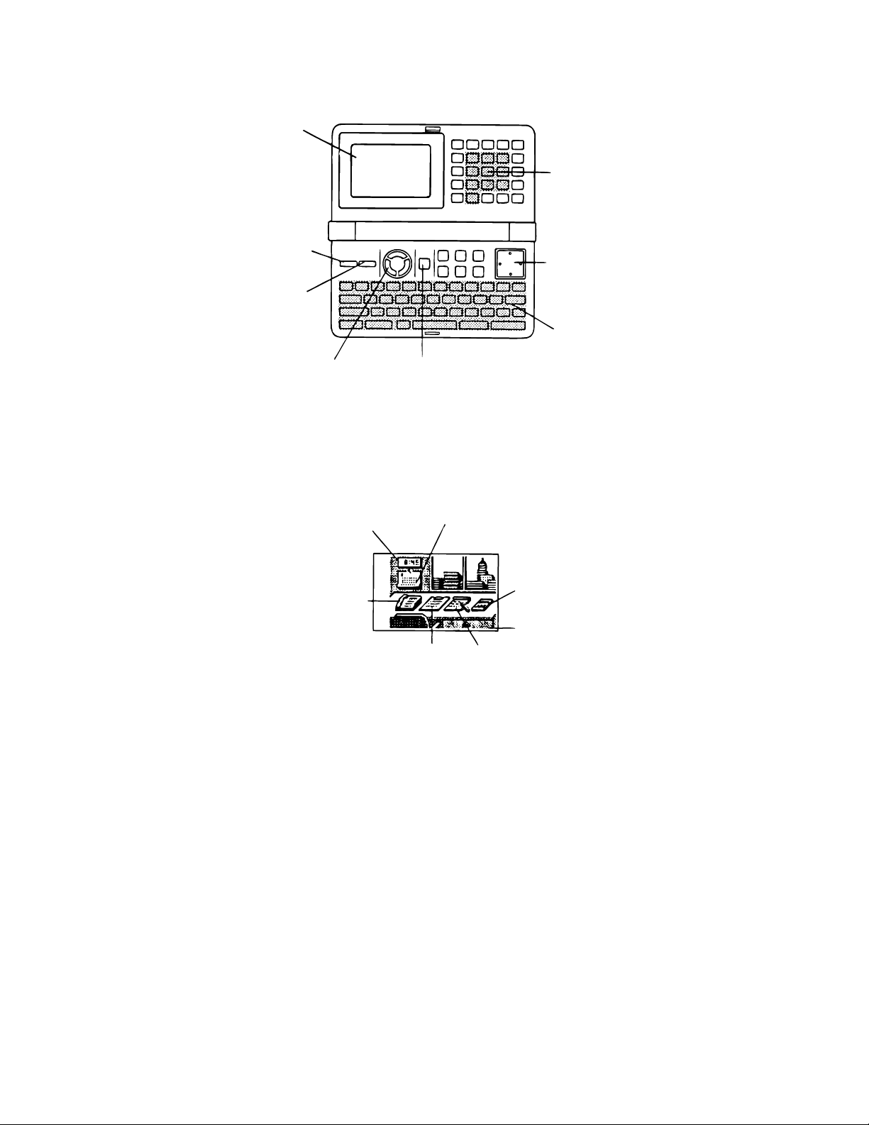
Display
ON key —
Press this key to
turn power on.
OFF key —
Press this key to
turn power off.
Number
Keys
Cursor Key
Pad
Alpha
keyboard
COLOR SELECT
keys
About the desktop...
The desktop gives you point-and-select access to the data management features of the CSF-8950.
Whenever you want to return to the desktop, simply press the MENU button.
Home Time, World
Time, and Alarm
Telephone Directory and
Business Card Directory
• Note that one of the icons on the desktop is flashing. This means that the icon is selected.
How to use the desktop
1. Use the cursor keys to move the flashing around the desktop until the one you want is selected
(flashing).
2. After selecting an icon, press OK to access the functions of that icon.
• Selecting some icons (like the Clock and Telephone) cause another selection screen to appear.
• Details on actually using the features and functions that you access from the desktop are described
in the other sections of this manual.
MENU key
Calendar, Schedule
Keeper, Reminder and
Expense Manager
To Do
Calculator
Secret Drawer
Memo
Changing the Desktop Screen's Window Scenery
You can change the scenery that is outside the desktop screen's window to any one of the scenes shown
below. Simply display the desktop screen and press the COLOR SELECT key that corresponds to the
scenery you want to select.
ORG: Night-time city scene
BLU: Daytime city scene
GRN: Beach scene
— 4 —
Page 7
Adjusting the Display Contrast
The following procedure describes how to adjust the color contrast, which controls the relative darkness
and lightness of each color on the display.
To adjust the display contrast
1. While the desktop is on the display, press FUNC.
2. Press 1 to select
SYSTEM
.
/////////// SYSTEM ///////////
1 SOUND
2 LANGUAGE
3 CAPACITY
4 CONTRAST
5 START UP
3. Press 4 to select
CONTRAST
.
//////////// CONTRAST ////////////
<O B G>
Pointer (currently
selected color)
(ORG)
(BLU)
(GRN)
4. Use and to move the pointer to the color whose contrast you want to set.
5. Use and to adjust the contrast of the currently selected color.
• You can adjust the overall contrast of the display by pressing or .
• Whenever you press one of the COLOR SELECT keys, the color contrast is returned to its initial
default setting.
6. After you finish adjusting the display contrast, press OK.
• Color contrast settings are registered as soon as you make them. Because of this, pressing either
OK or ESC quits the color contrast procedure only. Pressing ESC does not return the color contrast
setting to what is was.
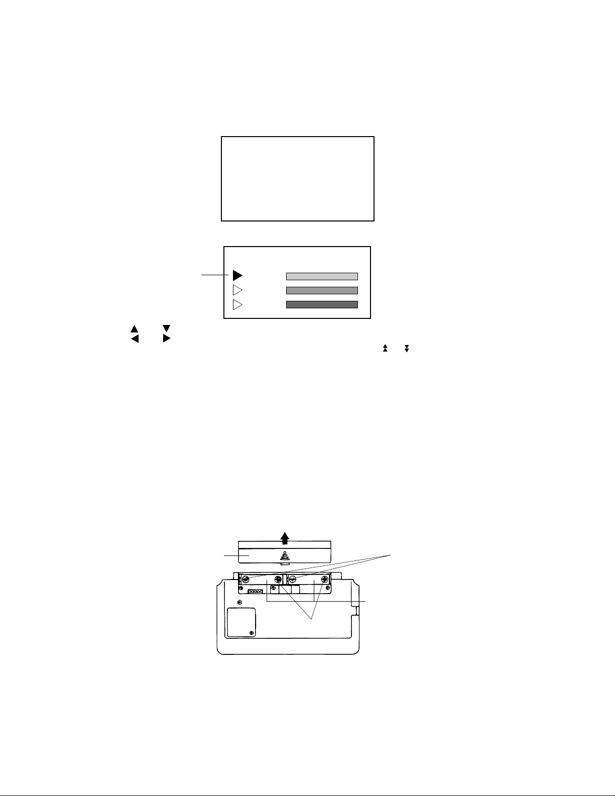
4. BATTERY REPLACEMENT
Main Battery
Before replacing the main batteries, note the following precautions:
• Do not remove the main batteries from the CSF Unit while back-up battery is removed.
• Be sure to replace both batteries at the same time, and do not use an old battery with a new one.
1. Press OFF to switch power OFF.
2. Slide the main battery holder in the direction indicated by the arrow.
Main battery holder
RESET
(–)
AAA-size
batteries
(+)
3. Remove both old batteries and replace them with two new ones.
• Make sure that the positive (+) and negative (-) ends are facing correctly.
4. Replace the holder.
5. Turn on power
• The Home Time screen always appears whenever you turn power on for the first time after
replacing batteries.
6. Check the Home Time setting and make changes if necessary.
— 5 —
Page 8
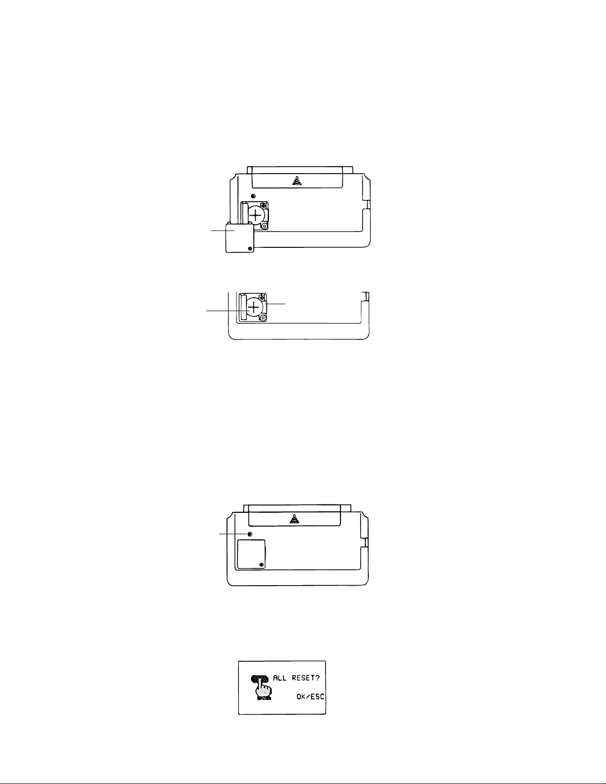
Back-up Battery
Before replacing the back-up battery, note the following precautions:
• Do not remove the back-up battery from the CSF Unit while main batteries are removed.
• Be sure to replace the back-up battery at least once a year. Otherwise, you run the risk of losing
data stored in memory.
1. Press OFF to switch power OFF.
2. Remove the screws that hold the back-up battery compartment cover in place, and remove the
cover.
RESET
Back-up battery
compartment
cover
3. Insert a thin, pointed object into (A) and remove the old battery.
CR2025 lithium
(A)
battery
4. Insert a new battery into the unit, making sure that the positive (+) side of the new battery is facing
up (so you can see it).
5. Replace the battery compartment cover and secure it by tightening its screw.
• Be careful that you do not over tighten the screw.
5. RESET OPERATION
1. Press ON to switch power ON.
2. Press the RESET button with a thin, pointed object.
RESET
button
RESET
Warning!
The next step deletes all data stored in the CSF Unit's memory. Make sure that you really want to delete
the data before you continue!
3. Press 1 to select
ALL RESET
.
Note
• The above message always appears in English, regardless of the system language setting.
— 6 —
Page 9

4. Press OK to reset the memory and delete all data or ESC to abort the reset operation without deleting
anything.
• After the ALL RESET operation is complete, the LANGUAGE screen appears on the display.
5. Select a system language.
• After you set the system language, the Home Time Screen appears.
6. Check the Home Time setting and make changes if necessary.
Following the all reset operation, the CSF Unit settings are initialized as noted below.
Home Time: LON
1996/1/1 MON
12:00 AM
12-hour format
World Time: NYC
Daily Alarm: 12:00 PM
Sound: Data alarm (Schedule alarm, Reminder alarm and To Do alarm) — ON
Daily alarm — OFF
Key — ON
Messages: English
Character input: CAPS
To perform SECRET RESET
Important!
• The following procedure erases all data stored in the secret drawer. Make sure you do not need any
of the data in the secret drawer before deleting it. You can transfer data you might need to the desktop
before performing this procedure.
• Note that this unit has no procedure for deleting the password only (and leaving secret drawer
contents) or secret drawer contents only (and leaving the password).
6. TO SAVE THE DATA TO OTHER MACHINE
CSF-8950 can transfer customer's data to another CSF-8950 with memory protection only when
replacing the LCD or the outer case.
To connect the CSF-8950 to another CSF Unit
1. Make sure that the power of both units is switched off.
2. Remove the covers from the data communications jacks on the two CSF Units.
3. Connect the two units using the SB-62 cable.
— 7 —
Page 10

How to transfer the data
1. The slave unit must be set the date of Feb. 3rd, 1901 into the memory under the calculator mode.
Operation : ON OK 1 DATE 2 DATE 3 DATE M+
If you don't set the date, the "PASSWORD" isn't transferred to the slave unit.
2. Check the hardware parameters of both unit, and if the both units have another condition, reset
as follows;
MENU FUNC 2 3
OK
3. Set up the slave unit.
• On the desktop, select the telephone icon
and press OK .
• Select the home icon and press OK .
• FUNC 2 2
DATA
RECEIVE OK!
TO STOP
PRESS [ ESC ]
4. Set up the customer's unit.
MENU FUNC 2 1 3 OK
If you can not succeed to transfer the data, press ESC key on both unit and try to transfer the data
again according to the above procedure.
— 8 —
Page 11

7. PIN FUNCTION
CPU (HD62119A03)
Pin No. Pin Name Input/Output Function
1 ~ 12 KO1 ~ KO12 O Key common signal
13 ~ 2 0 KI1 ~ KI8 I Key input signal
21 BUFON O Chip selecting signal for RAM
2 2 IT2 I Interrupt input
2 3 IT0 — Interrupt input
24 ~ 42 AO0 ~ AO18 O Address bus
43 OEBO O Enable signal
4 4 WEBO O Enable signal to write
49 ~ 51 CS4BO ~ CS6BO O Chip selecting signals
52 ~ 5 9 IO0 ~ IO7 I Data bus
62, 63 OPT0, OPT1 O Output point for check
64 ~ 71 PORT0 ~ PORT7 I/O Input/output port
72 VSS — GND
73, 74 PI, PO — Power for ceramic oscillator
7 5 VL C — Power
76, 77 XO, XI — Power
78 VCC — Power for LSI
79 VREG2 — Power
80, 81 TS1, TS2 I Terminal for test
82 VSSR — GND
8 3 BZZ1 O Buzzer signal output
8 4 BZZ2 O Buzzer signal output
85 VSS — GND
86 OCLK O Clock
87 ITOFF I/O Terminal for power switch
89 SW I Reset switch
9 0 VDB — Power
91 ~ 94 VD1 ~ VD4 — Power for doubler
95 VREG1 — Regulator power for LSI
96 VREG4 — Regulator power for ROM
9 7 VREG5 — Regulator power
98, 99 VDT1I, VDT2I I Terminal for detector
100 VREG3 — Regulator power for RAM
— 9 —
Page 12

8. DIAGNOSTIC PROGRAM
y
RESET
CP57
Bottom View
CP39
MAIN SWITCH
To enter the diagnostic program, proceed as follows;
1 : Open the battery cover and slide the main switch to the arrow side.
2 : Press ON while shorting the pads CP39 and CP57.
STEP OPERATION DISPLAY NOTE
Enter the
diagnostics
Press ON while shorting
the pads CP39 and CP57.
///// SELF TEST PROG /////
PRESS OK KEY
QUIT BY OFF KEY
CASIO JULY 1995
Main menu OK ////////// TEST MENU //////////
1 DISPLAY
2 MEMORY
3 KEY & TIME
4 BUZZER
5 I / F
6 CONTRAST
7 RESET
DIsplay
Check
1 ////////// DISPLAY //////////
1 DISPLAY
2 FRAME FREQ.
1 No color, no displa
OK Orange color is displayed
OK Green color is displayed
OK Blue color is displayed
OK Checkers are displayed
OK Reverse checkers are displayed
OK Frame is displayed
OK Dots at the 4 corners are
displayed
OK Vertical 4 colors are displayed
OK Horizontal 4 colors are displayed
OK ////////// TEST MENU //////////
1 DISPLAY
2 MEMORY
3 KEY & TIME
4 BUZZER
5 I / F
6 CONTRAST
7 RESET
— 10 —
Page 13

STEP OPERATION DISPLAY NOTE
Memory
Check
Memory
Check
2 /////////// MEMORY ///////////
1 WRITE 1
2 READ 1
3 WRITE 2
4 READ 2
5 DUMP
6 CHECK SUM
1
RAM WRITE 1
/////////// MEMORY ///////////
1 WRITE 1
2 READ 1
3 WRITE 2
4 READ 2
5 DUMP
6 CHECK SUM
2
EXECUTING !!
COMPLETE !!
256KB
OK /////////// MEMORY ///////////
1 WRITE 1
2 READ 1
3 WRITE 2
4 READ 2
5 DUMP
6 CHECK SUM
3
RAM WRITE 2
Write the test pattern 1 into RAM
After 3 sec.
Read the test pattern 1 from RAM
After 3 sec.
Write the test pattern 2 into RAM
/////////// MEMORY ///////////
1 WRITE 1
2 READ 1
3 WRITE 2
4 READ 2
5 DUMP
6 CHECK SUM
4
EXECUTING !!
COMPLETE !!
256KB
OK /////////// MEMORY ///////////
1 WRITE 1
2 READ 1
3 WRITE 2
4 READ 2
5 DUMP
6 CHECK SUM
After 3 sec.
Read the test pattern 2 from RAM
After 3 sec.
— 11 —
Page 14

STEP OPERATION DISPLAY NOTE
Memory
Check
OK /////////// MEMORY ///////////
1 WRITE 1
2 READ 1
3 WRITE 2
4 READ 2
5 DUMP
6 CHECK SUM
6 CHECK SUM
CS5
TYPE
SIZE
SUM
EXOR
ROM
512kB
1A8D
XX
OK /////////// MEMORY ///////////
1 WRITE 1
2 READ 1
3 WRITE 2
4 READ 2
5 DUMP
6 CHECK SUM
ESC ////////// TEST MENU //////////
1 DISPLAY
2 MEMORY
3 KEY & TIME
4 BUZZER
5 I / F
6 CONTRAST
7 RESET
KEY CHECK 3 ///////// KEY & TIME /////////
1 RANDOM
2 AUTO
3 TIME
1 ///////// KEY & TIME /////////
1 RANDOM
2 AUTO
3 TIME
1, ON, OFF, T, G ....... 16 25 26 46 5 8 ..... To push the key sequentially that
OK ////////// TEST MENU //////////
1 DISPLAY
2 MEMORY
3 KEY & TIME
4 BUZZER
5 I / F
6 CONTRAST
7 RESET
Buzzer
Check
4 /////////////// BZZ ///////////////
1 BEEP
2 ALARM
3 ALARM
Check SUM value
key code is being appeared in
the display.
1 : Key input sound
2 : Sound alarm 1
3 : Sound alarm 2
— 12 —
Page 15

STEP OPERATION DISPLAY NOTE
(
)
ESC ////////// TEST MENU //////////
1 DISPLAY
2 MEMORY
3 KEY & TIME
4 BUZZER
5 I / F
6 CONTRAST
7 RESET
Interface
Check
5 //////////////// I/F ////////////////
1 TRANS
2 RECEIVE
3 ASCII
4 LOOP
The parameter can be changed
as follows;
Key "5" : Bit length 7 or 8 bit
Key "6" : Parity bit N(Non),
E(Even) or O(Odd)
Key "7" : BPS 9(9600) or 4(4800)
7N9
CONTRAST
ADJ.
1
EXECUTING !!
Send the code "H"
2 No display Display the received charactor.
3
4
EXECUTING !!
EXECUTING !!
Send the ASCII code
Loop back check
ESC //////////////// I/F ////////////////
1 TRANS
2 RECEIVE
3 ASCII
4 LOOP
7N9
6 ////////// TEST MENU //////////
1 DISPLAY
2 MEMORY
3 KEY & TIME
4 BUZZER
5 I / F
6 CONTRAST
7 RESET
Contrast up :
or SHIFT +
//////////// CONTRAST ////////////
<O B G>
Contrast adjustment
(ORG)
Contrast down :
or SHIFT +
(BLU)
(GRN)
Cursor keys //////////// CONTRAST ////////////
<O B G>
(ORG)
Adjust the color using cursor
keys until the primary colors
appear accurately.
(BLU)
GRN
— 13 —
Page 16

STEP OPERATION DISPLAY NOTE
OK ////////// TEST MENU //////////
1 DISPLAY
2 MEMORY
3 KEY & TIME
4 BUZZER
5 I / F
6 CONTRAST
7 RESET
RESET 7 NAME?
TELEPHONE
0
END
9. ERROR MESSAGE
Message
NO DATA!
DATA ITEM NOT
FOUND!
MEMORY FULL!
ALARM TIME
ALREADY USED!
ALARM TIME
ALREADY PASSED!
SECRET DATA!
PASSWORD
MISMATCH!
Meaning
Search operation attempted when no data is
stored in memory.
Data specified in search operation does not
exist in memory.
No more room in memory for storage of data.
Attempt to set a Schedule Keeper, a Reminder or a To Do alarm time that is already
used for another entry.
Attempt to set a Schedule Keeper, a Reminder or a To Do alarm time for a time/date
that is already passed.
Alarm for a secret memory area data item is
sounding.
Attempt to enter the secret memory area
using a password that does not match the one
preset for the secret area.
Action
Current search operation cannot be performed.
Change specification or cancel search.
Delete unnecessary data
items from memory.
Set a different alarm time or
change the existing alarm time
to another one.
Set a different alarm time (for
a future time/date).
Enter the secret memory area
to view details of the alarm.
Use the correct password.
TRANSMIT ERROR!
STOPPED!
SAME TYPE
ALREADY USED!
NOTICE!
CONSULT THE
OWNER'S MANUAL!
Error during data communications.
Data communication has been interrupted.
Attempt to store a label that is identical to one
already stored.
• This message appears when this is the first
time you ever turned on the CSF Unit.
• Data corrupted by strong impact, electrostatic charge, etc.
— 14 —
Cancel the data communications operation and try again.
Stop the data communication
procedure and try again.
Use a different label.
Perform the ALL RESET operation (page 6).
See page 6 of this manual.
Page 17

10. SCHEMATIC DIAGRAMS
MAIN PCB
— 15 —
MODEL RAM
CSF-7950 1Mbit
CSF-7950 1Mbit
LSI4 LSI5
C13 C14
– use
– not use
R32 IC10
Page 18

DISPLAY PCB
— 16 —
Page 19

Key Matrix (Keyboard side)
— 17 —
Page 20

Key Matrix (Display side)
— 18 —
Page 21

11. PARTS LIST
N Item Code No. Parts Name Specification Q'ty R
EQ FQ
CPU BOARD ASS'Y
D4,5 2390 0364 Schottky diode MA713-TX
D6,7 2301 2359 Chip diode MA151K-(TX)
IC1 2105 3213 IC BU4066BCF-T1
IC12 2105 2821 CMOS-IC TC7S04F-TE85R
IC3 2105 4704 IC RH5RE25AA-T1
IC4 2105 2737 CMOS-IC RH5RL50AA-T1
IC6 2105 4228 CMOS-IC RH5VL25CA-T1
IC7 2105 4914 CMOS-IC RH5VL23CA-T1
IC8 2105 4144 CMOS-IC RH5VL26CA-T1
IC9 2011 8806 IC TC74HC04AF-TP1
IC10 2101 0651 IC TC74HC00AF-TP1
J1 3501 8778 Mini jack HSJ1563-010010
LSI1 2012 1078 LSI HD62119A03
LSI3 2012 3108 LSI UPD23C4001EJGW-C19
LSI4,5 2011 9422 LSI CXK581000AM-10LLB
Q5 2254 0287 FET 2SK1133-T1B
Q6 2259 0959 Chip digital transistor DTC114YKT-146
VR1 2765 1869 Chip volume MVR32HXBRN503
X1 2590 1764 Ceramic oscillator CSTCS3.45MG001-TC
X2 7110 0642 Crystal oscillator DT-26S
37 6409 6310 Battery plate - EF02DB10100
38 6410 9810 Battery plate + EF01DB10107
22
22
11
11
11
11
11
11
11
11
11
11
11
11
22
11
11
11
11
11
11
11
C
C
B
B
B
B
B
B
B
B
B
C
A
A
A
B
B
C
C
C
X
X
The following electronic parts will not be supplied from CASIO.
C1~4,9,19, Chip capacitor MCH312F105ZP
20,38
C5,8,12,13, Chip capacitor MCH212F104ZK
14,35,36,39
C6,7 Chip capacitor MCH312F474ZP
C18 Chip tantalum capacitor ECST0JY106R
C33,34 Electrolytic capacitor UVR1A101MDA6TP
C37 Chip capacitor MCH215C221KK
C41 Chip capacitor MCH215A120JK
C42 Chip capacitor MCH215A180JK
C43 Chip capacitor MCH215C102KK
R1 Chip resistor MCR10EZHJ153
R3 Chip resistor MCR10EZHJ823
R16 Chip resistor MCR10EZHG102
R17 Chip resistor MCR10EZHG202
R18 Chip resistor MCR10EZHG392
R19 Chip resistor MCR10EZHG822
R20 Chip resistor MCR10EZHFX1053
R22 Chip resistor MCR10EZHFX5622
R23 Chip resistor MCR10EZHFX1003
R25 Chip resistor MCR10EZHJ182
R26 Chip resistor MCR10EZHJ473
R27 Chip resistor MCR10EZHJ102
R28 Chip resistor MCR10EZHG105
R31 Chip resistor MCR10EZHJ475
R33 Chip resistor MCR10EZHJ105
Notes: N – New parts R – A : Essential
R – Rank B : Stock recommended
– Quantity used per
Q C : Others
X : No stock recommended
— 19 —
88
88
22
11
22
11
11
11
11
11
11
11
11
11
11
11
11
11
11
11
11
11
11
11
FQ : B.O.S.S
EQ : Others
Page 22

N Item Code No. Parts Name Specification Q'ty R
EQ FQ
R34 Chip resistor MCR10EZHJ273
R50 Chip resistor MCR10EZHJ184
R21,51 Chip resistor MCR10EZHJ000
CHIP ON BOARD BONDING
LSI2 6413 5320 COF3011-F1 sub ass'y A340214*1
THR1 2755 0147 Thermister 104HT
The following electronic parts will be not supplied from CASIO.
11
11
22
11
11
A
C
C51~55 Chip capacitor MCH312F105ZP
C56~61 Chip capacitor MCH212C154KP
C62,63 Chip capacitor MCH213F105ZP
C64,65,67 Chip capacitor MCH212F104ZK
C66 Chip capacitor MCH215A120JK
COMPONENTS
N 1 6417 6070 Upper cabinet (Keyboard)) FAADB321011
2 6416 6650 Key top(Red) KB1DB324002
3 6416 6720 Key top(Blue) KB1DB324029
N 4 6417 6030 Key top FM ass'y KGDB3210015
5 6416 6730 Rubber sheet(56KL) LADB3210003
6 6416 6790 Battery spring - EF06DB32104
7 6416 6680 CPU board ass'y DB32XX3100L*1
8 3122 2380 Buzzer EFB-S55C41A8
N 9 6417 6100 Lower cabinet(Keyboard) FABDB321093
N 9 6417 6110 Lower cabinet(Keyboard) FABDB321085
10 6416 6660 Key top(Green) KB1DB324011
11 5610 8990 Heat seal(96P) FX200P50027
12 3335 6006 LCD CD1024A-TS
13 5610 8980 Heat seal(64P) FX200P50035
14 6416 6780 Battery spring +/- EF05DB32101
15 6416 6690 Chip on board bonding DB32XX3F00R*1
16 5610 8950 Heat seal(32P) FX200P80104
17 5610 8960 Heat seal(10P) FX200P80112
N 18 6417 6080 Battery cover FADDB321022
19 6416 6620 Switch knob ass'y DB32XX4A00V*1
N 20 6417 6090 Battery cover FAD0L961019
21 6512 1020 Screw MAA80009301
N 22 6417 6040 Display plate EL5K0004204
23 6416 6820 Newton ring spacer ELDB3200000
N 24 6417 6060 Upper cabinet (Display) FAADB322018
25 6416 6640 Key top ass'y KCDB3220006
26 6416 6740 Rubber sheet(25KL) LADB3220009
27 5610 8970 Heat seal FX201P00074
28 4321 1120 PCB 60.29 X 56 DADB32XX311
29 6416 6920 Push button FB3DB321007
N 30 6417 6120 Lower cabinet(Display) FABDB3220H1
N 30 6417 6130 Lower cabinet(Display) FABDB3220G9
31 6416 6930 Push button plate EX07DB32109
32 6408 5830 Rubber sheet LADB0140101
33 6416 6850 Hinge RB LC610000001
34 6416 5860 Color label Z850 C440972-1
Notes: N – New parts R – A : Essential
R – Rank B : Stock recommended
– Quantity used per
Q C : Others
X : No stock recommended
55
66
22
33
11
11
11
11
11
11
11
11
11
10
01
11
11
11
11
11
11
11
11
11
11
11
11
11
11
11
11
11
11
11
11
10
01
11
11
11
11
FQ : B.O.S.S
EQ : Others
C
C
C
C
C
X
B
X
C
C
C
A
A
A
X
B
A
A
C
C
C
X
B
X
C
C
C
A
X
C
C
C
C
C
C
X
— 20 —
Page 23

N Item Code No. Parts Name Specification Q'ty R
EQ FQ
35 6511 7160 Connector cap LC120000102
36 6416 6950 Battery spring + EF04DB32109
Parts prices will be informed separately by Parts Price List.
11
11
C
X
Notes: N – New parts R – A : Essential
R – Rank B : Stock recommended
– Quantity used per
Q C : Others
X : No stock recommended
— 21 —
FQ : B.O.S.S
EQ : Others
Page 24

12. EXPLODED VIEW
1
2
3
4
5
33
10
11
12
13
22
23
24
6
7
35
37
38
8
9
14
15
36
16
17
18
19
25
26
27
28
29
30
32
20
21
— 22 —
31
34
Page 25

8-11-10, Nishi-Shinjuku
Shinjuku-ku, Tokyo 160, Japan
Telephone: 03-3347-4926
 Loading...