

Page 1
(without price)
INDEX
CSF-5350/5550/5750 (ZX-889)
JUN. 1996
CSF-5750
R
Page 2

CONTENTS
FEATURES..............................................................................................................................1
SPECIFICATIONS...................................................................................................................2
GENERAL GUIDE ...................................................................................................................4
BATTERY REPLACEMENT....................................................................................................7
RESET OPERATION...............................................................................................................8
TO SAVE THE DATA ..............................................................................................................9
PIN FUNCTION......................................................................................................................10
DIAGNOSTIC PROGRAM.....................................................................................................11
ERROR MESSAGE ...............................................................................................................14
SCHEMATIC DIAGRAMS .....................................................................................................15
EXPLODED VIEW .................................................................................................................19
PARTS LIST ..........................................................................................................................20
Page 3

FEATURES
3-color Display
The display shows data in three colors: orange, blue and green. Different colors can be used to highlight
specific dates in the Calendar, and even the color of text data can be specified.
Selectable Main Menu Format
Choose between a graphic desktop or an icon list for the Main Menu from which you can select the mode
you want.
Do Today Function
Every time you turn on the unit, any Schedule Keeper items scheduled for that date appear on the display.
Powerful Data Bank Functions
Telephone Directory, Business Card Directory, Memo, To Do, Expense Manager, Reminder, and Schedule
Keeper.
Secret Function
Look up confidential information using a secret password.
Calendar - Schedule Keeper - Reminder - To Do Linking
Reminder and To Do items are automatically displayed in the applicable Schedule Keeper dates. Markers
appear on the Calendar display to indicate dates for which Schedule Keeper, Reminder, and To Do items
are scheduled.
Timepiece with Home time and World Time
Dual timekeeping for two different locations.
Powerful Alarm Functions
In addition to the standard daily alarm, you can also set alarms for Schedule Keeper, Reminder, and To
Do items.
Calculator
A 12-digit arithmetic calculator is just the thing for those quick, on-the-go calculations.
Data Communication
Exchange data with another CSF Unit or with a CASIO SF Unit.
Note
• This unit is equipped with a demonstration feature, which is activated before the unit is shipped from
the factory. Be sure to turn the demonstration off before using the unit for normal operarion.
If you don't, any display color balance settings you make will be cleared every time you turn the unit off.
— 1 —
Page 4

SPECIFICATIONS
MEMORY CAPACITY
Memory capacity differs according to model. The following shows the memory capacity for each available
model.
Model Memory
CSF-5350 64K bytes
CSF-5550 128K bytes
CSF-5750 256K bytes
The following shows the number or items that can be stored in each model (CSF-5350/5550/5750).
TELEPHONE DIRECTORY
Approximately 2,700/5,700/11,600, under the following conditions:
8-character name
10-character telephone number
Approximately 1,300/2,900/5,900, under the following conditions:
8-character name
10-character telephone number
20-character address
BUSINESS CARD DIRECTORY
Approximately 700/1,500/3,000, under the following conditions:
10-character employer name
8-character personal name
10-character telephone number
10-character position
10-character department
20-character address
MEMO
Approximately 2,600/5,400/11,100, 20-character memos.
TO DO
Approximately 1,600/3,400/7,100, under the following conditions:
20 character description
Deadline set
SCHEDULE KEEPER
Approximately 1,500/3,200/6,500, under the following conditions:
20 character description
Illustration used
Starting time specified, alarm time set
Approximately 2,000/4,100/8,500, under the following conditions:
20 character description
Illustration not used
Starting time specified, no alarm time
REMINDER
Approximately 3,300/6,900/14,200, under the following conditions:
10 character description
Alarm time set
Approximately 3,700/7,800/16,000, under the following conditions:
10 character description
No alarm time
— 2 —
Page 5

EXPENSE MANAGER
Approximately 1,800/3,800/7,700, under the following conditions:
10 character description
Expense type and payment type set
MAIN MODES:
Telephone Directory, Business Card Directory, Memo, Schedule Keeper, To Do, Expense Manager,
Reminder, Calendar, Home Time, World Time and Calculator
DATA STORAGE:
Storage and recall of telephone, business card, memo, schedule, to do, expense, reminder data; calendar
display; secret memory area; editing; memory status display
CLOCK:
Worldtime; reminder alarm; schedule alarm; to do alarm; daily alarm; accuracy under normal temperatures:
±3 seconds average
CALCULATION:
12-digit arithmetic calculations; arithmetic constants (+, -, ×, ÷); independent memory; percentages; square
roots; 24-digit approximations; date calculations; other mixed calculations
GENERAL:
Display element: 16-column × 4-line LCD
Main component: LSI
Power supply: Three lithium batteries (CR2032)
Current consumption:
ON: 1.6 mA or under (TEL mode)
OFF: 13 µA or under
Low battery message: 7.2 V ± 2.0%
Forced power off: 6.7 V ± 2.0%
Battery life:
Main: Approximately 90 hours continuous display in Telephone Directory;
approximately 70 hours repeating one minute of input and 10 minutes of
display in Telephone Directory
Power consumption: 0.08 W
Auto power off: Approximately 6 minutes after last key operation
Operating temperature: 0°C ~ 40°C (32°F ~ 104°F)
Dimensions:
Unfolded: 8.65H × 150W × 160D mm (5/16"H × 57/8"W × 65/16"D)
Folded: 18.8H × 150W × 80D mm (3/4"W × 57/8"W × 31/8"D)
Weight: 150 g (5.3 oz) including batteries
— 3 —
Page 6

GENERAL GUIDE
OFF key —
Press this key
to turn power
OFF.
ON key —
Press this key
to turn power
ON.
Display
Cursor Key
Pad
Keyboard
COLOR SELECT
keys
ABOUT THE DEMONSTRATION FEATURE...
The CSF Unit comes with a Demonstration feature that shows sample screens and input data for each of
its functions. When the Demonstration feature is turned on, the CSF Unit automatically shows the various
demonstration screens in sequence each time you turn it on.
• You can interrupt an ongoing demonstration at any time by pressing any key.
TO TURN THE DEMONSTRATION FEATURE ON AND OFF
1. While the main menu is on the display, press FUNC.
2. Press 1 to select SYSTEM.
3. Press to display the second SYSTEM Menu.
4. Press 2 to select START UP.
5. Use and to move the pointer to DEMO.
6. Use and to turn the Demonstration feature on and off.
7. After making the setting you want, press OK.
Note
• The demonstration feature screens will not be displayed when the Do Today feature is turned on.
MENU key
SELECTING A MAIN MENU FORMAT
You can select either a graphic desktop or an icon list as the Main Menu format. You get the same features
and functions, regardless of the Main Menu format you select.
Important!
• All of the examples in this manual are illustrated using the icon list, and all references to the Main Menu
apply to both the graphic desktop and the icon list, unless otherwise specified.
— 4 —
Page 7
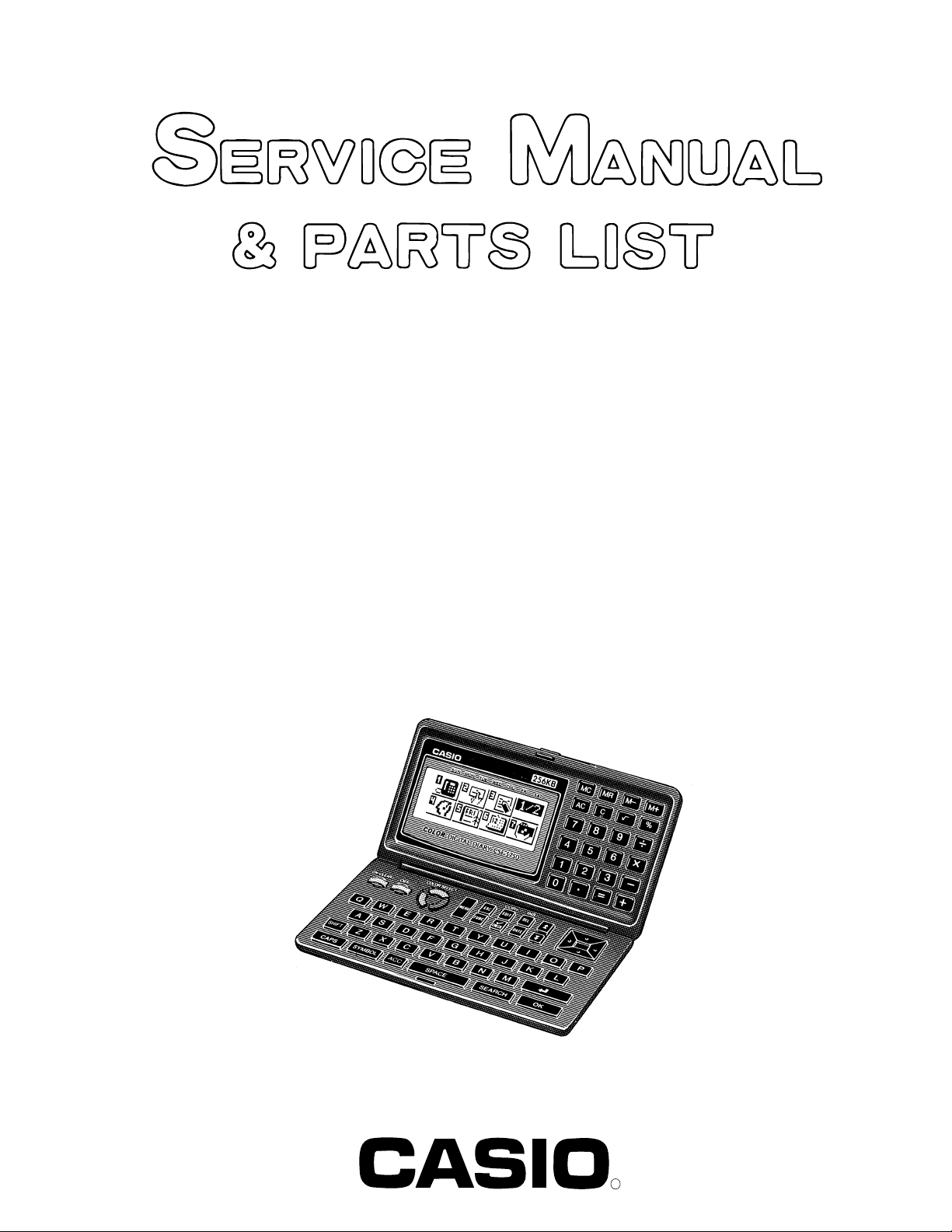
ICON LIST FORMAT
The Main Menu icon list format provides two screens of icons from which you can choose the function you
want.
1 2 3
4 5 6 7
1 Telephone Directory 4 To Do
2 Business Card Directory 5 Schedule Keeper
3 Memo 6 Calendar
7 Expense Manager
1 2 3
4 5 6
1 Reminder 4 Daily Alarm
2 Home Time 5 Calculator
3 World Time 6 Secret Memory Area
TO ENTER A MODE
Use the , , , and cursor keys to move the highlighting to the mode you want to select and press
OK. Or you can simply input the number in the upper left corner of an icon to directly enter the corresponding
mode without pressing OK.
TO CHANGE FROM PAGE 1 TO PAGE 2
• While any icon of Page 1 is highlighted, press or MENU to change to Page 2.
• While an icon in the bottom row of Page 1 is highlighted, press to change to Page 2.
• While the Expense Manager icon is highlighted, press to change to Page 2.
TO CHANGE FROM PAGE 2 TO PAGE 1
• While an icon in the top row of Page 2 is highlighted, press to change to Page 1.
• While the Reminder icon is highlighted, press to change to Page 1.
• While any icon of Page 2 is highlighted, press or MENU to change to Page 1.
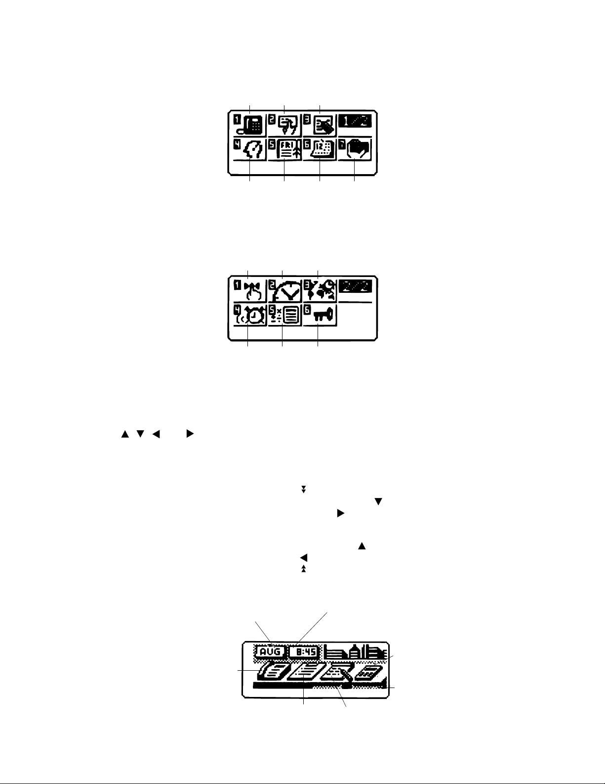
DESKTOP FORMAT
Calendar, Schedule
Keeper, Reminder and
Expense Manager
Home Time, World
Time, and Alarm
Telephone Directory
and Business Card
Directory
To Do
— 5 —
Calculator
Secret Drawer
Memo
Page 8

The desktop gives you point-and-select access to the data management features of the CSF Unit.
Whenever you want to return to the desktop, simply press the MENU button.
• Note that one of the icons on the desktop is flashing, This means that the icon is selected.
HOW TO USE THE DESKTOP
1. Use the cursor keys to move the flashing around the desktop until the one you want is selected (flashing).
2. After selecting an icon, press OK to access the functions of that icon.
• Selecting some icons (like the Clock and Telephone) cause another selection screen to appear.
• Details on actually using the features and functions that you access from the desktop are described in
the other sections of this manual.
CHANGING THE DESKTOP SCREEN'S WINDOW SCENERY
You can change the scenery that is outside the desktop screen's window to any one of the scenes shown
below. Simply display the desktop screen and press the COLOR SELECT key that corresponds to the
scenery you want to select.
ORG: Night-time city scene
BLU: Daytime city scene
GRN: Beach scene
ADJUSTING THE COLOR BALANCE
The following procedure describes how to adjust the color contrast, which controls the relative darkness
and lightness of each color on the display.
TO ADJUST THE COLOR BALANCE
1. While the desktop is on the display, press FUNC.
2. Press 1 to select SYSTEM.
3. Press to display the second SYSTEM menu.
4. Press 1 to select COLOR BALANCE.
Pointer (currently
selected item)
(ORG)
(BLU)
(GRN)
INITIALIZE
5. Use and to move the pointer to the color whose contrast you want to set.
6. Use and to adjust the contrast of the currently selected color.
• You can adjust the overall contrast of the display by pressing or .
7. After you finish adjusting the display contrast, press OK.
• Color contrast settings are registered as soon as you make them. Because of this, pressing either OK
or ESC quits the color contrast procedure only. Pressing ESC does not return the color contrast setting
to what is was.
Note
• Temperature changes can cause changes in background color and the tint of display colors .
— 6 —
Page 9

BATTERY REPLACEMENT
Before replacing the batteries, note the following precaution:
• Be sure to replace all batteries with a full set of new ones, and do not mix old batteries with new ones.
1. Press OFF to switch power OFF.
2. Slide the battery compartment cover in the direction indicated by the arrow.
3. Slide the battery switch to the "REPLACE 1" setting.
REPLACE
BATTERIES
NORMAL
4. Remove the battery holder by sliding it in the direction indicated by the arrow in the illustration.
Caution
Be sure to remove only one battery at a time. Otherwise, you will lose all data stored in memory.
5. Replace the old battery with a new one, making sure that the positive (+) side of the new battery is facing
up (so you can see it).
6. Replace the battery holder and faten it in place.
7. Slide the battery switch to the "REPLACE 2, 3" setting and repeat steps 4 through 6 for the other
batteries.
• Be sure to replace all three batteries, using CR2032 lithium batteries only. Never mix old batteries with
new ones.
8. Slide the battery switch to the "NORMAL" setting.
• You will not be able to turn the unit on if the battery switch is not in the "NORMAL" setting.
9. Replace the battery compartment cover.
• The Home Time screen always appears whenever you turn power on for the first time after replacing
batteries.
10. Check the Home Time setting and make changes if necessary.
— 7 —
Page 10

RESET OPERATION
TO PERFORM ALL RESET
1. Open the battery compartment and press the RESET button.
RESET button
• At this time the following message appears on the display.
CLEAR MEMORY AND
SET UP THE UNIT
FOR OPERATION?
YES/NO
2. Make sure that YES is highlighted. If NO is highkighted, press to move the highlighting to YES.
Warning!
The next step deletes all data stored in the CSF Unit's memory. Make sure that you really want
to delete the data before you continue!
3. Press OK to start the RESET procedure.
• After the ALL RESET operation is complete, the LANGUAGE screen appears on the display.
4. Use the procedure under "Setting the System Language" to select a system language.
• After you set the system language, the Home Time Screen appears.
5. Check the Home Time setting and make changes if necessary.
Following the all reset operation, the CSF Unit settings are initialized as noted below.
Home Time: LON
1996/1/1 MON
12:00 AM
12-hour format
World Time: NYC
Daily Alarm: 12:00 PM
To perform SECRET RESET
Important!
• The following procedure erases all data stored in the secret drawer. Make sure you do not need any
of the data in the secret drawer before deleting it. You can transfer data you might need to the desktop
(page 9) before performing this procedure.
• Note that this unit has no procedure for deleting the password only (and leaving secret drawer
contents) or secret drawer contents only (and leaving the password).
Sound: Data alarm (Schedule alarm, Reminder
alarm and To Do alarm) — ON
Daily alarm — OFF
Key — ON
Messages: English
Character input: CAPS
1. Press the MENU key.
2. Press the FUNC key and then input 1 to select SYSTEM.
3. Press twice to change to the third screen (3/3), and then input 1 to select SECRET RESET.
4. Press OK.
— 8 —
Page 11

TO SAVE THE DATA
CSF-5350/5550/5750 can transfer the customer's data to another CSF unit with memory protection only
when replacing the LCD or the outer case.
TO CONNECT THE CSF UNIT TO ANOTHER CSF UNIT
1. Make sure that the power of both units are switched off.
2. Remove the covers from the data communications jacks on the two CSF Units.
3. Connect the two units using the SB-62 cable.
HOW TO TRANSFER THE DATA
1. Under calculator mode, set the date of the slave unit to Feb. 3rd, 1901.
Operation : ON OK 1 DATE 2 DATE 3 DATE M+
If you do not set the date, the "PASSWORD" is not transferred to the slave unit.
2. Check the hardware parameters of both unit, and if both units have another condition, reset as follows;
MENU FUNC 2 3
//////////// SET UP PAR. ////////////
PARITY E/O/NN
BIT LENGTH 77 / 8
BPS 4800 / 96009600
OK
3. Set up the slave unit.
• On the desktop, select the telephone icon
and press OK .
• Select the home icon and press OK .
• FUNC 2 2
4. Set up the customer's unit.
MENU FUNC 2 1 3 OK
DATA
DATA
RECEIVE OK!
TO STOP
PRESS [ ESC ]
SENDING!
TO STOP
PRESS [ ESC ]
If you can not succeed to transfer the data, press ESC key on both units and try to transfer the data again
following the procedure above.
— 9 —
Page 12

PIN FUNCTION
CPU HCD62121A02 (HC-3017) : COB
NOTE: The CPU is bonding on the PCB. If the CPU is defective, replace the Z889-1 PCB ass'y
because the CPU cannot be replaced.
Pin No. Pin Name Input/Output Function
1 ~ 14 KO14 ~ KO1 O Key common signal
15 ~ 2 2 KI8 ~ KI1 I Key input signal
23 BUFON O Chip select for RAM
2 4 IT2 I Interrupt input
2 5 IT0 I Interrupt input
26 ~ 46 AO20 ~ AO0 O Address bus
47 ~ 5 4 IO0 ~ IO7 I / O Data bus
55 OEBO O Output enable signal for RAM
5 6 WEBO O Write enable signal for RAM
57 ~ 64 CS10BO ~ CS3BO O Chip selecting signals
6 5 O P T7 O Reset signal output
69 ~ 72 OPT3 ~ OPT0 O Changeover signal
7 3 PORT7 I Receiving terminal for data communication
7 4 PORT6 I Receiving terminal for data communication
7 5 PORT5 O Transmitting terminal for data communication
7 6 PORT4 O Transmitting terminal for data communication
80 PORT0 I Low battery message for back-up battery (2.6V)
81 VSS I GND
82 PI I 1MHz clock input
8 3 PO O 1MHz clock output
8 4 VDD I +3V source
8 5 XO O 4.3MHz clock output
86 XI I 4.3MHz clock input
8 7 VCC I +3V source
88 VREG2 O Voltage for main switch detection
89, 90 TS1, TS2 — Test terminals of factory purpose only
91 VSSR I GND
9 2 BZZ1 O Buzzer signal output
9 3 BZZ2 O Buzzer signal output
94 VSS I GND
95 OCLK O Clock output
9 6 ITOFF I Sw itching terminal from main switch
97 TEMU — Test terminals of factory purpose only
98 SW I Receiving terminal for reset switch
9 9 VDB I +3V source
100 VREG1 — Test terminals of factory purpose only
101 VREG4 O +3V source for ROM
102 VREG5 — Test terminals of factory purpose only
103 VDT1I I Forced power off detecting terminal (2.3V)
104 VDT2I I Low battery message for main battery (2.5V)
105 VREG3 — +3V source for RAM
— 10 —
Page 13

DIAGNOSTIC PROGRAM
Test Pad
Bottom View
To enter the diagnostic program, proceed as follows;
1 : Turn the power switch ON and open the battery cover.
2 : Press Reset Button while shorting the Test pad.
STEP OPERATION DISPLAY NOTE
Enter the
diagnostics
Main menu OK TEST
Display
Check
Press ON while shorting
the Test pad.
1 DISPLAY
1 No color, no display
OK Orange color is displayed
OK Green color is displayed
OK Blue color is displayed
OK Checkers are displayed
OK Reverse checkers are displayed
OK Frame is displayed
OK Dots at the 4 corners are
OK Vertical 4 colors are displayed
OK Horizontal 4 colors are displayed
OK TEST
///// SELF TEST PROG /////
PRESS OK KEY
QUIT BY OFF KEY
CASIO MAR 1996
1 DISP
2 MEMORY
3 KEY
1 DISPLAY
2 FRAME FREQ.
displayed
1 DISP
2 MEMORY
3 KEY
4 BUZZER
5 I/F
6 CONT
7 RESET
4 BUZZER
5 I/F
6 CONT
7 RESET
— 11 —
Page 14

STEP OPERATION DISPLAY NOTE
Memory
Check
Memory
Check
2 MEMORY
1 WR 1
2 READ 1
1
MEMORY
1 WR 1
2 READ 1
2
OK MEMORY
1 WR 1
2 READ 1
3
MEMORY
1 WR 1
2 READ 1
4
3 WR 2
4 READ 2
5 DUMP
6 CHKSUM
RAM WRITE 1
3 WR 2
4 READ 2
5 DUMP
6 CHKSUM
EXECUTING !!
COMPLETE !!
64/128/256 KB
3 WR 2
4 READ 2
5 DUMP
6 CHKSUM
RAM WRITE 2
3 WR 2
4 READ 2
5 DUMP
6 CHKSUM
EXECUTING !!
Write the test pattern 1 into RAM
After 1 sec.
Read the test pattern 1 from RAM
After 1 sec.
Write the test pattern 2 into RAM
After 1 sec.
Read the test pattern 2 from RAM
Memory
Check
COMPLETE !!
64/128/256 KB
OK MEMORY
1 WR 1
2 READ 1
5
OK MEMORY
1 WR 1
2 READ 1
6 CHECK SUM
TY SZ SUM XOR
C5 0 512 DFB0 XX
OK MEMORY
1 WR 1
2 READ 1
ESC TEST
1 DISP
2 MEMORY
3 KEY
3 WR 2
4 READ 2
5 DUMP
6 CHKSUM
XXXX
3 WR 2
4 READ 2
5 DUMP
6 CHKSUM
3 WR 2
4 READ 2
5 DUMP
6 CHKSUM
4 BUZZER
5 I/F
6 CONT
7 RESET
After 1 sec.
Wiring check for ROM
— 12 —
Page 15

STEP OPERATION DISPLAY NOTE
KEY CHECK 3 KEY & TIME
1 RANDOM
2 AUTO
3 TIME
1 No display
MC, MR, M–, M+ ..... 00 01 02 03 ..... To push the key sequentially that
key code is being appeared in
the display.
Buzzer
Check
Interface
Check
OK TEST
1 DISP
2 MEMORY
3 KEY
4 BUZZER 1 : Key input sound
ESC TEST
1 DISP
2 MEMORY
3 KEY
5 I/F
7N9
4 BUZZER
5 I/F
6 CONT
7 RESET
1 BEEP
2 ALARM 1
3 ALARM 2
4 BUZZER
5 I/F
6 CONT
7 RESET
1 TRANS
2 RECEIVE
3 ASCII
4 LOOP
2 : Sound alarm 1
3 : Sound alarm 2
The parameter can be changed
as follows;
Key "5" : Bit length 7 or 8 bit
Key "6" : Parity bit N(Non),
E(Even) or O(Odd)
Key "7" : BPS 9(9600) or 4(4800)
1
EXECUTING !!
Send the code "H"
CONTRAST
ADJ.
2 No display Display the received charactor.
3
4
ESC I/F
EXECUTING !!
EXECUTING !!
1 TRANS
Send the ASCII code
Loop back check
2 RECEIVE
7N9
3 ASCII
4 LOOP
6 TEST
1 DISP
2 MEMORY
3 KEY
Contrast up :
or SHIFT +
(ORG)
4 BUZZER
5 I/F
6 CONT
7 RESET
Contrast adjustment
(BLU)
Contrast down :
or SHIFT +
(GRN)
INITIALIZE
Cursor keys Adjust the color using cursor keys
until the primary colors appear
accurately.
— 13 —
Page 16

STEP OPERATION DISPLAY NOTE
OK TEST
1 DISP
2 MEMORY
3 KEY
RESET 7 NAME?
TELEPHONE
0
ERROR MESSAGE
Message
NO DATA!
DATA ITEM NOT
FOUND!
MEMORY FULL!
Search operation attempted when no data is
stored in memory.
Data specified in search operation does not
exist in memory.
No more room in memory for storage of data.
Meaning
4 BUZZER
5 I/F
6 CONT
7 RESET
END
Action
Current search operation cannot be performed.
Change specification or cancel search.
Delete unnecessary data
items from memory.
ALARM TIME
ALREADY USED!
ALARM TIME
ALREADY PASSED!
SECRET DATA!
PASSWORD
MISMATCH!
TRANSMIT ERROR!
STOPPED!
SAME TYPE
ALREADY USED!
Attempt to set a Schedule Keeper, a Reminder or a To Do alarm time that is already
used for another entry.
Attempt to set a Schedule Keeper, a Reminder or a To Do alarm time for a time/date
that is already passed.
Alarm for a secret memory area data item is
sounding.
Attempt to enter the secret memory area
using a password that does not match the one
preset for the secret area.
Error during data communications.
Data communication has been interrupted.
Attempt to store a label that is identical to one
already stored.
Set a different alarm time or
change the existing alarm time
to another one.
Set a different alarm time (for
a future time/date).
Enter the secret memory area
to view details of the alarm.
Use the correct password.
Cancel the data communications operation and try again.
Stop the data communication
procedure and try again.
Use a different label.
— 14 —
Page 17

SCHEMATIC DIAGRAMS
Main Block
— 15 —
NOTE: D100 and D101 are not mounted.
Page 18

Display Block
— 16 —
Page 19

Memory Block
— 17 —
Page 20

Main Key Block Sub Key Block
— 18 —
Page 21

EXPLODED VIEW
2
3
4
5
1
25
6
7
8
9
10
11
21
26
15
27
16
28
17
18
19
20
29
30
31
12
13
14
24
38
22
23
— 19 —
32
37
33
34
35
36
Page 22

PARTS LIST
Q
N Item Code No. Parts Name Specification
CPU Board Ass'y
D1 2390 0847 Diode MA718-(TX) 111111C
D5 2390 0364 Diode MA713-TX 111111C
IC1 2114 4795 IC TC74HC4066AF(EL) 110011B
IC4,IC11 2105 2884 IC XC62CP5002PR 222222B
IC6 2105 5474 IC XC61AN7202PR 111111B
IC7 2105 5481 IC XC61AN6702PR 111111B
IC9 2105 5222 IC TC74HC04AF(EL) 111111B
IC10 2105 5236 IC TC74HC32AF(EL) 110011B
IC12 2105 1561 IC TC7S04F-TE85R 110011B
LSI3 2012 4508 LSI UPD23C4001EJGW-C52 111111B
LSI4,LSI5 2012 1659 LSI TC551001BFL-10V(S) 001122B
LSI6,LSI7 2012 3192 LSI TC55257DFL-7085V 220000B
J1 3501 6538 Jack HSJ1169-012010 111111C
Q6 2259 0959 Transistor DTC114YKT-146 111111C
Q100 2250 1281 Transistor 2SA1179M5,M6,M7-TB 111111C
VR1 2765 1869 Volume MVR32HXBRN503 111111C
X1 2590 1967 Resonator CSTC4.30MG-TC 111111X
X2 2590 1288 Crystal C-002RX 111111X
19 6418 9180 Battery Plate - EF02DB36109 333333X
20 6418 9170 Battery Plate + EF01DB36106 333333X
The following electronic parts will be not supplied from CASIO.
C1~C4,C9 Chip Capacitor MCH312F105ZP 555555X
C7 Electrolytic Capacitor ECEA1AKA330I 111111X
C10 Electrolytic Capacitor ECEA1CKA220I 111111X
C19~C20 Chip Capacitor MCH315F104ZK 222222X
C37 Chip Capacitor MCH185A221JK 111111X
C41,C42 Chip Capacitor MCH185A150JK 222222X
C70 Chip Capacitor CM105W5R102K50AT 111111X
CB5~CB6,CB10, Chip Capacitor MCH183F104ZK 006600X
C5,C12,C35
CB7 Chip Capacitor MCH183F104ZK 110011X
R1 Chip Resistor MCR03EZHJ153 111111X
R2~R3 Chip Resistor MCR03EZHJ301 222222X
R10~R11 Chip Resistor MCR03EZHJ105 222222X
R16 Chip Resistor MCR03EZHG822 111111X
R17 Chip Resistor MCR03EZHG392 111111X
R18 Chip Resistor MCR03EZHG202 111111X
R19 Chip Resistor MCR03EZHG102 111111X
R20 Chip Resistor MCR03EZHJ752 111111X
R21,R26 Chip Resistor MCR03EZHJ473 222222X
R22,R23 Chip Resistor MCR03EZHF1003 222222X
R25 Chip Resistor MCR03EZHJ182 111111X
R27 Chip Resistor MCR03EZHJ102 111111X
R28 Chip Resistor MCR03EZHG105 111111X
R32,R100 Chip Resistor MCR03EZHJ000 002200X
R50 Chip Resistor MCR03EZHJ124 111111X
R71~R73 Chip Resistor MCR03EZHJ823 333333X
R74,R100 Chip Resistor MCR03EZHJ000 220000X
R75,R100 Chip Resistor MCR03EZHJ000 000022X
R102~R103 Chip Resistor MCR03EZHJ474 222222X
Notes: N – New parts Essential FQ, JQ : For B.O.S.S.
Q – Quantity used per unit Stock recommended EQ, IQ : Others
R – Rank Others
R – A :
B :
C :
X :
No stock recommended
5350 5550 5750
AT AQ EQ FQ IQ JQ
R
— 20 —
Page 23

Q
N Item Code No. Parts Name Specification
5350 5550 5750
AT AQ EQ FQ IQ JQ
LCD Board Ass'y
16 3335 6293 LCD CD1061-TS 111111B
17 6418 9160 Sponge Cushion FH100035305 222222X
18 6418 9150 Shield Plate LC54DB30019 222222X
29 6418 9100 Heat Seal FX2P028XXX0 111111B
30 6417 3871 OC3015-F1 Sub Ass'Y C340532A*3 111111B
Display PCB Ass'y
THR1 2755 0189 Thermister TH20-3S104FT 111111X
The following electronic parts will be not supplied from CASIO.
C51~C55,C58 Chip Capacitor MCH312F105ZP 666666X
C56,C57 Chip Capacitor MCH212C154KP 222222X
C59 Chip Tantalum Capacitor ECST1AY106R 111111X
C60 Chip Tantalum Capacitor ECST1DY335R 111111X
CB3 Chip Capacitor MCH183F104ZK 111111X
R36 Chip Resistor MCR03EZHJ823 111111X
R208 Chip Resistor MCR03EZHJ000 111111X
Component
1 6418 8880 Hinge Tape HGQ00000501 110000X
1 6418 9590 Hinge Tape HGQ00000609 001100X
1 6418 9360 Hinge Tape HGQ00000706 000011X
2 6418 8810 Hinge (B) FC0DB362106 110000X
2 6418 9550 Hinge (B) FC0DB362114 001100X
2 6418 9310 Hinge (B) FC0DB362122 000011X
3 6418 8950 Pin LC03DB36104 222222C
4 6418 8960 Pin (L) LC03DB36201 222222C
5 6418 8940 Hinge (A) FC0DB361100 110000X
5 6418 9630 Hinge (A) FC0DB361118 001100X
5 6418 9390 Hinge (A) FC0DB361126 000011X
6 6418 8920 Upper Cabinet (KB) FAADB361102 110000X
6 6418 9610 Upper Cabinet (KB) FAADB361111 001100X
6 6418 9370 Upper Cabinet (KB) FAADB361129 000011X
7 6418 8860 Hinge Stopper EF15DB36109 222222X
8 6418 8820 Rubber Sheet (KB) LADB3610001 110000X
8 6418 9560 Rubber Sheet (KB) LADB3610010 001100X
8 6418 9330 Rubber Sheet (KB) LADB3628028 000011X
9 6511 7160 RB Insert LC120000102 111111C
10 6418 9080 CPU Board Ass'y DB36XX3100M*1 110000B
10 6419 0590 CPU Board Ass'y DB36AX3100R 001100B
10 6418 9440 CPU Board Ass'y DB36BX3100U*1 000011B
11 3122 2380 Buzzer EFB-S55C41A8 111111X
12 6418 9040 Lower Cabinet (KB) FABDB361184 010000X
12 6418 9050 Lower Cabinet (KB) FABDB361109 100000X
12 6418 9650 Lower Cabinet (KB) FABDB361150 001000X
12 6418 9660 Lower Cabinet (KB) FABDB361192 000100X
12 6418 9420 Lower Cabinet (KB) FABDB361168 000001X
12 6418 9430 Lower Cabinet (KB) FABDB361176 000010X
13 6418 8910 Battery Cover Label HGQ00000404 111111X
14 6418 8900 Battery Cover FADDB361105 110000C
14 6418 9600 Battery Cover FADDB361113 001100C
14 6419 0580 Battery Cover FADDB361121 000011C
15 6418 8890 Newton Ring Spacer ELCDB361001 111111X
21 6418 8850 Overlay Mylar EL4Q0001100 111111X
Notes: N – New parts Essential FQ, JQ : For B.O.S.S.
Q – Quantity used per unit Stock recommended EQ, IQ : Others
R – Rank Others
R – A :
B :
C :
X :
No stock recommended
— 21 —
R
Page 24

N Item Code No. Parts Name Specification
22 6418 9120 Heat Seal FX2P0800001 111111B
23 6418 8800 Switch Knob Ass'y DB36XX4A00L 111111C
24 6413 7330 Battery Holder FC0DB231109 333333C
25 6418 8840 Display Plate EL5Q0001101 110000B
25 6418 9570 Display Plate EL5Q0001306 001000B
25 6418 9580 Display Plate EL5Q0001403 000100B
25 6418 9340 Display Plate EL5Q0001501 000010B
25 6418 9350 Display Plate EL5Q0001608 000001B
26 6418 8930 Upper Cabinet (DIS) FAADB362109 110000X
26 6418 9620 Upper Cabinet (DIS) FAADB362117 001100X
26 6418 9380 Upper Cabinet (DIS) FAADB362125 000011X
27 6418 8830 Rubber Sheet (DIS) LADB3620007 110000X
27 6418 9320 Rubber Sheet (DIS) LADB3620015 001111X
28 6419 1710 LCD Board Ass'y DB36XX3200T*1 111111B
31 6418 9110 Disply PCB Ass'y DB36XX3E00N 111111B
32 6418 9090 Heat Seal FX2P1200007 111111B
33 4321 2070 Key PCB DADB36XX301 111111C
34 6418 8990 Push Button Plate EX07DB36007 111111C
35 6418 8980 Push Button FB3DB361106 111111X
36 6418 8970 Lower Cabinet (DIS) FABDB362113 110000X
36 6418 9640 Lower Cabinet (DIS) FABDB362130 001100X
36 6418 9400 Lower Cabinet (DIS) FABDB362156 000010X
36 6418 9410 Lower Cabinet (DIS) FABDB362172 000001X
37 6418 9000 PC Sheet EL5K0007106 111111X
38 6511 8400 Rubber Sheet LADB0220105 111111X
Q
5350 5550 5750
AT AQ EQ FQ IQ JQ
R
Parts prices will be informed separately by Parts Price List.
Notes: N – New parts Essential FQ, JQ : For B.O.S.S.
Q – Quantity used per unit Stock recommended EQ, IQ : Others
R – Rank Others
R – A :
— 22 —
B :
C :
X :
No stock recommended
Page 25

CASIO COMPUTER CO.,LTD.
MA0900661A
Service
8
-11-10
Shinjuku-ku, Tokyo 160, Japan
Telephone: 03-3347-4926
Division
, Nishi-Shinjuku
 Loading...