

Page 1

CFX-9970G (ZX-936A)
AUG. 1997
(without price)
CFX-9970G
R
Page 2

CONTENTS
1. SPECIFICATIONS ........................................................................................... 3
2. GENERAL GUIDE
2-1. Modes....................................................................................................... 4
2-2. Color Contrast Adjustment .................................................................... 5
2-3. Power Supply .......................................................................................... 6
3. RESET OPERATION....................................................................................... 9
4. DATA COMMUNICATIONS
4-1. Connecting Two Units .......................................................................... 10
4-2. Before Starting Data Communications ............................................... 10
4-3. Performing Data Transfer Operation................................................... 11
4-4. Data Communication Precautions ...................................................... 14
5. OPERATION CHECK .................................................................................... 15
6. TO SAVE THE DATA .................................................................................... 18
7. TROUBLESHOOTING................................................................................... 20
8. OPERATION PROBLEMS ............................................................................ 21
9. ERROR MESSAGE ....................................................................................... 22
10. SCHEMATIC DIAGRAMS ............................................................................. 25
11. PARTS LIST .................................................................................................. 30
12. EXPLODED VIEW ......................................................................................... 30
— 2 —
Page 3
1. SPECIFICATIONS
Variables: 28
Calculation range:
±1 × 10
(except in ALGBR Mode)
–99
to ±9.999999999 × 1099 and 0. Internal operations use 15-digit mantissa.
Exponential display range: Norm1: 10–2 > [x], [x] > 10
(except in ALGBR Mode) Norm2: 10–9 > [x], [x] > 10
10
=
10
=
Program capacity: 60 kbytes (max.)
Power supply:
Main: Four AAA-size batteries (LR03(AM4) or R03 (UM-4))
Back-up: One CR2032 lithium battery
Power consumption: 0.2 W
Battery life*:
Main:
LR03(AM4): Approximately 230 hours (continuous display of main menu)
Approximately 2 years (power off)
R03(UM-4): Approximately 140 hours (continuous display of main menu)
Approximately 2 years (power off)
* The ALGBR Mode requires more electrical power than other modes, so extensive use
of the ALGBR Mode shortens battery life.
Back-up: Approximately 2 years
Auto power off:
Power is automatically turned off approximately six minutes after last operation except when drawing dynamic
graphs.
The calculator automatically turns off if it is left for about 60 minutes with a calculation stopped by an output
command ( ), which is indicated by the “-Disp-” message on the display.
Ambient temperature range: 0 °C ~ 40 °C
Dimensions: 27.1 mm H × 85 mm W × 181.5 mm D (1 1/8" H × 3 3/8" W × 7 1/8" D)
Weight: 230 g (including batteries)
Current consumption:
TYP [µA] MAX [µA]
ON (MENU) 2961 3941
OFF 41.3
— 3 —
Page 4
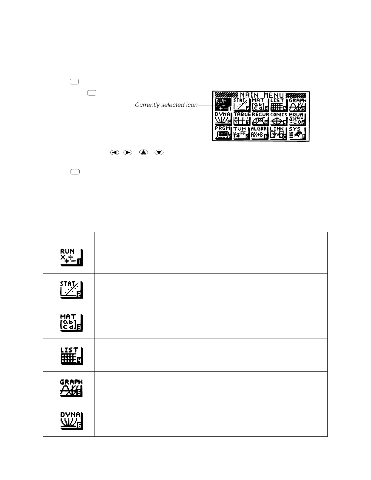
2. GENERAL GUIDE
2-1. Modes
• To select an icon
1. Press
MENU
to display the Main Menu.
MENU
2. Use the cursor keys ( , , , ) to move the highlighting to the icon you want.
3. Press
EXE
to display the initial screen of the mode whose icon you selected.
• You can also enter a mode without highlighting an icon in the Main Menu by inputting the number or letter
marked in the lower right corner of the icon.
• Use only the procedures described above to enter a mode. If you use any other procedure, you may end
up in a mode that is different than the one you thought you selected.
The following explains the meaning of each icon.
Icon Mode Name Description
RUN Use this mode for arithmetic calculations and function calculations,
and for calculations involving binary, octal, decimal and hexadecimal values.
STATistics Use this mode to perform single-variable (standard deviation) and
paired-variable (regression) statistical calculations, to perform tests,
to analyze data and to draw statistical graphs.
MATrix Use this mode for storing and editing matrices.
LIST Use this mode for storing and editing numeric data.
GRAPH Use this mode to store graph functions and to draw graphs using the
functions.
DYNAmic graph Use this mode to store graph functions and to draw multiple versions
of a graph by changing the values assigned to the variables in a
function.
— 4 —
Page 5
Icon Mode Name Description
TABLE Use this mode to store functions, to generate a numeric table of
different solutions as the values assigned to variables in a function
change, and to draw graphs.
RECURsion Use this mode to store recursion formulas, to generate a numeric
table of different solutions as the values assigned to variables in a
function change, and to draw graphs.
CONICS Use this mode to draw graphs of implicit functions.
EQUAtion Use this mode to solve linear equations with two through six
unknowns, quadratic equations, and cubic equations.
PRoGraM Use this mode to store programs in the program area and to run
programs.
Time Value of Use this mode to perform financial calculations and to draw cash flow
Money and other types of graphs.
ALGeBRa Use this mode to obtain mathematical expression results using
natural mathematical display notation.
LINK Use this mode to transfer memory contents or back-up data to
another unit.
SYStem Use this mode to check how much memory is used and remaining,
to delete data from memory, and to initialize (reset) the calculator.
It also lets you adjust display contrast.
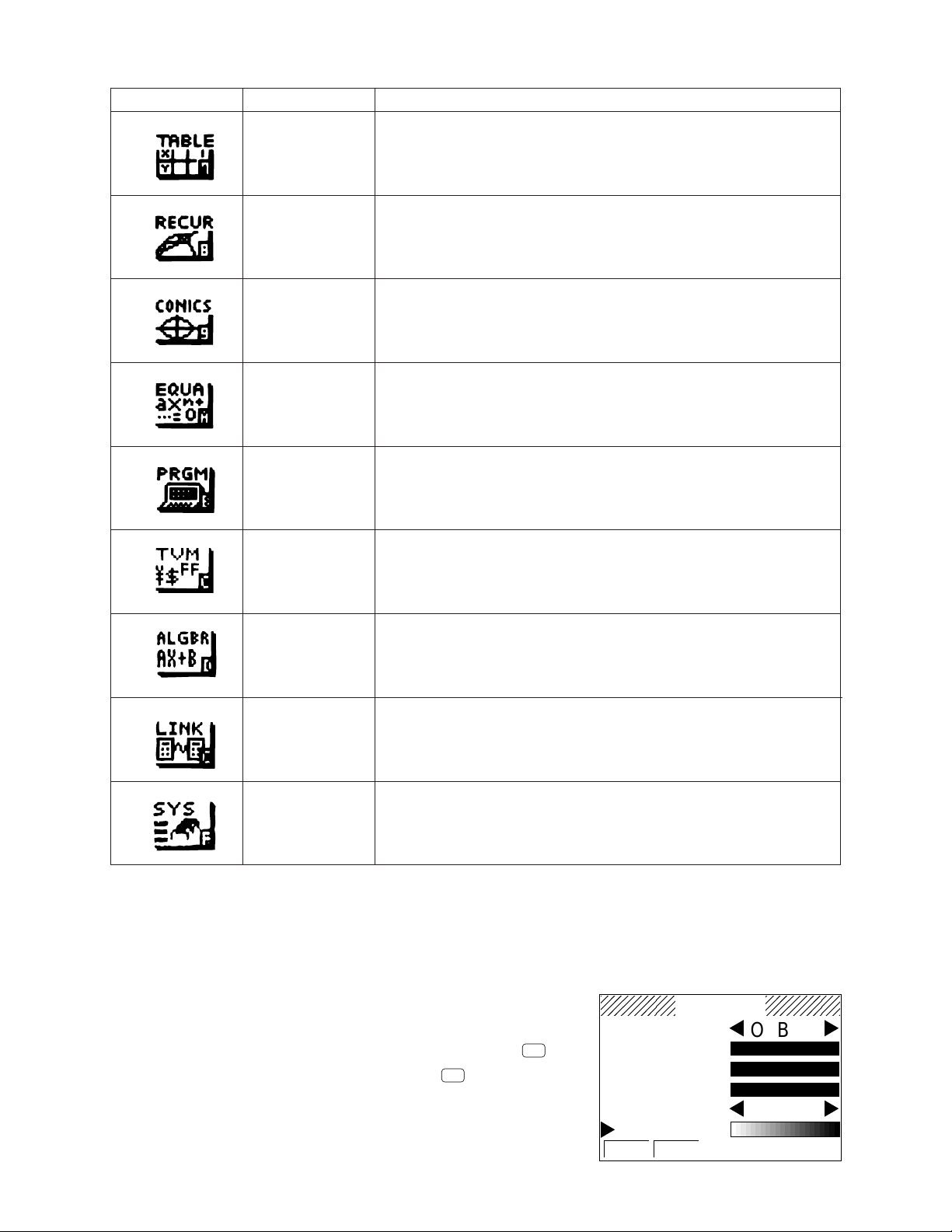
2-2. Color Contrast Adjustment
Adjust the color whenever objects on the display appear dim or difficult to see. There are two different settings
you can make to get color the way you want it.
• Color contrast
• Tint adjustment for each color
• To display the color adjustment screen
COLOR
O B G
1. Highlight the SYS icon in the Main Menu and then press
2. Highlight the Color Contrast and then press .
• {INIT}/{IN•A} ... {initialize highlighted color}/{initialize all colors}
EXE
EXE
.
ORANGE
BLUE
GREEN
– +
Use the following procedures while the color adjustment screen is on
the display to adjust the color contrast and tint settings.
CONTRAST
INIT IN·A
— 5 —
Page 6
• To adjust the color contrast
1. Use the cursor and keys to move the pointer so it is next to CONTRAST.
2. Press the cursor key to make the display darker and the cursor key to make it lighter. Holding
down either key changes the setting at high speed.
• To adjust the color tint
1. Use the cursor and keys to move the pointer so it is next to the color (ORANGE, BLUE, GREEN)
whose tint you want to adjust.
2. Press the cursor key to give the color greener tint and the cursor key to give it an orange tint. Holding
down either key changes the setting at high speed.
• To exit the color adjustment screen
Press
MENU
to return to the Main Menu.
• It is recommended that you always adjust the CONTRAST setting first, and then adjust the tint settings
for individual colors.
• You can change the CONTRAST setting at any time without displaying the color adjustment screen.
Simply press
SHIFT
and then or to change the setting. Press
SHIFT
once again after get the display
looking the way you want.
2-3. Power Supply
This unit is powered by four AAA-size (LR03(AM4) or R03(UM-4)) batteries. In addition, it uses a single
CR2032 lithium battery as a back up power supply for the memory.
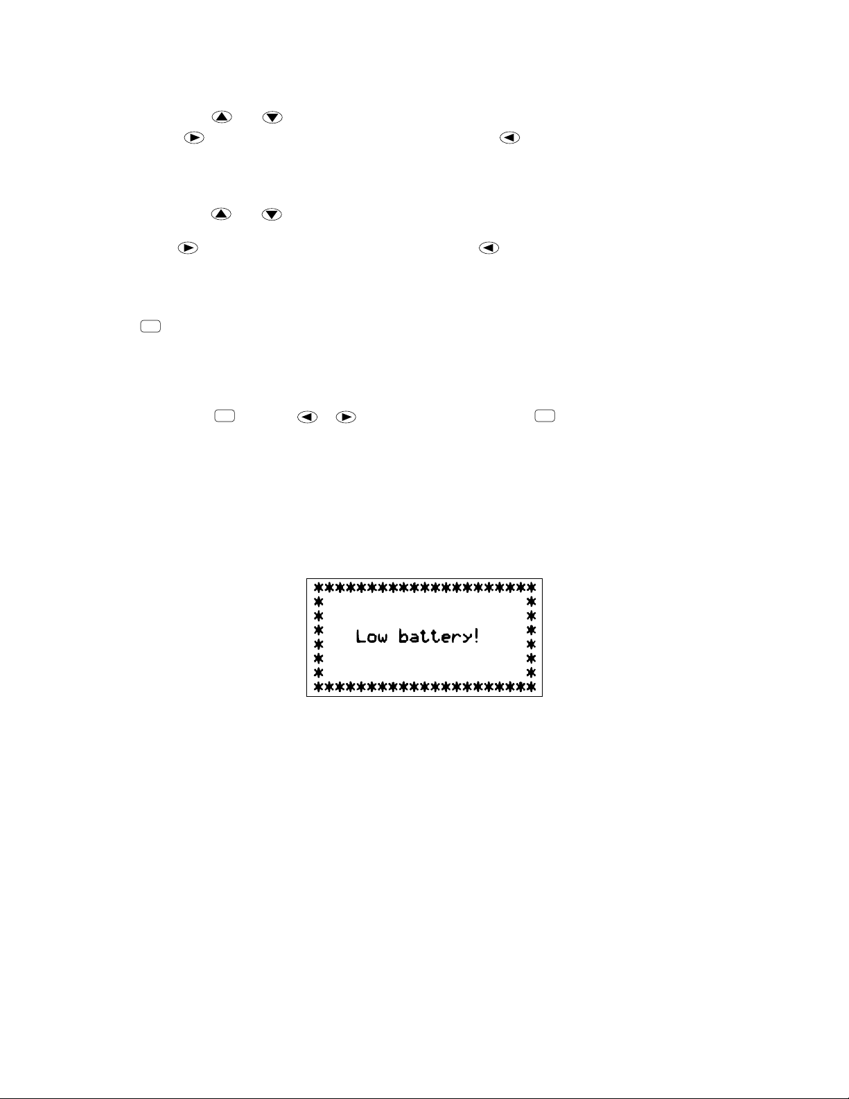
If the following message appears on the display, immediately stop using the calculator and replace batteries.
If you try to continue using the calculator, it will automatically turn power off, in order to protect memory
contents. You will not be able to turn power back on until you replace batteries.
Be sure to replace the main batteries at least once every two years, no matter how much you use the calculator
during that time.
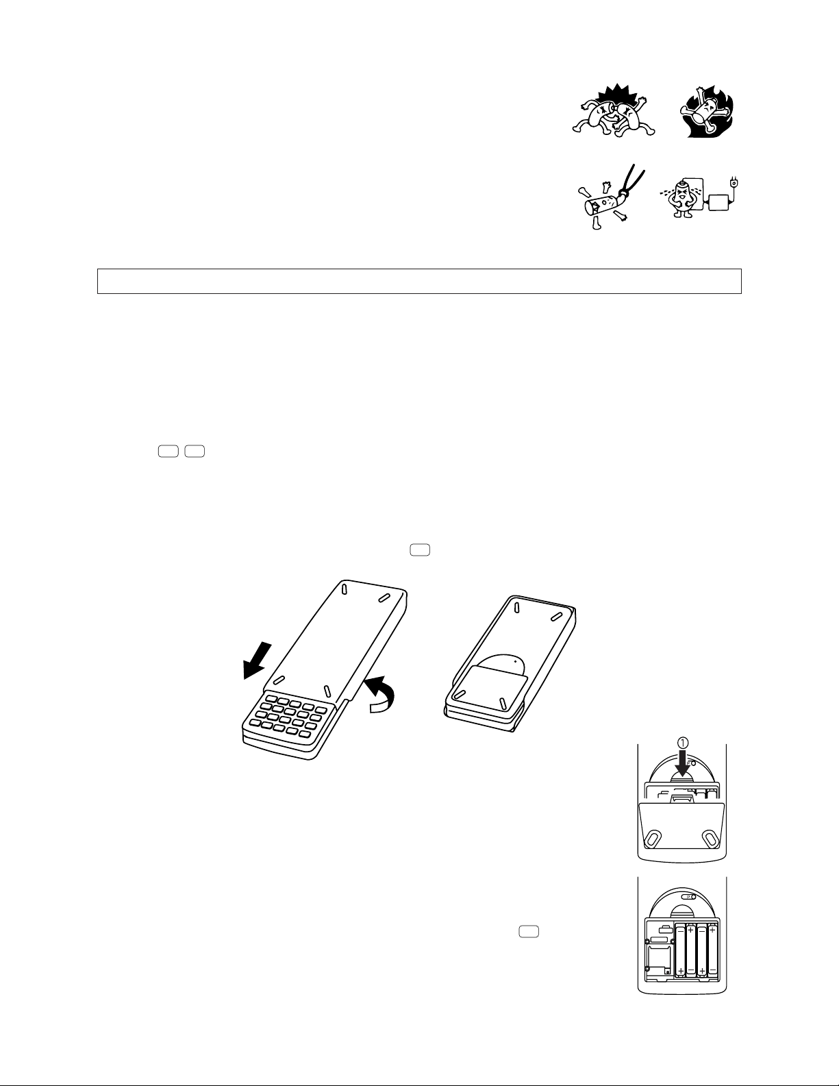
Warning!
If you remove both the main power supply and the memory back up batteries at the same time, all memory
contents will be erased. If you do remove both batteries, correctly reload them and then perform the reset
operation.
Replacing Batteries
Precautions:
Incorrectly using batteries can cause them to burst or leak, possibly damaging the interior of the unit. Note the
following precautions:
— 6 —
Page 7
• Be sure that the positive (+) and negative (-) poles of each battery are facing
in the proper directions.
• Never mix batteries of different types.
• Never mix old batteries and new ones.
• Never leave dead batteries in the battery compartment.
• Remove the batteries if you do not plan to use the unit for long periods.
• Never try to recharge the batteries supplied with the unit.
• Do not expose batteries to direct heat, let them become shorted, or try to
take them apart.
(Should a battery leak, clean out the battery compartment of the unit
immediately, taking care to avoid letting the battery fluid come into direct contact with your skin.)
Keep batteries out of the reach of small children. If swallowed, consult with a physician immediately.
• To replace the main power supply batteries
* Never remove the main power supply and the memory back up batteries from the unit at the same time.
* Never turn the calculator on while the main power supply batteries are removed from the calculator or
not loaded correctly. Doing so can cause memory data to be deleted and malfunction of the calculator.
If mishandling of batteries causes such problems, correctly load batteries and then perform the RESET
operation to resume normal operation.
* Be sure to replace all four batteries with new ones.
SHIFT
1. Press
OFF
to turn the calculator off.
Warning!
* Be sure to turn the unit off before replacing batteries. Replacing batteries with power on will cause data
in memory to be deleted.
2. Making sure that you do not accidently press the
AC/ON
key, slide the case onto the calculator and then turn
the calculator over.
3. Slide the back cover from the unit by pulling with your finger at the point marked 1.
4. Remove the four old batteries.
5. Load a new set of four batteries, making sure that their positive ( + ) and negative
( - ) ends are facing in the proper directions.
6. Replace the back cover.
7. Turn the calculator front side up and slide off its case. Next press
power.
— 7 —
AC/ON
to turn on
Page 8
• Power supplied by memory back up battery while the main power supply batteries are removed for
replacement retains memory contents.
• Do not leave the unit without main power supply batteries loaded for long periods. Doing so can cause
deletion of data stored in memory.
• If the figures on the display appear too light and hard to see after you turn on power, adjust the tint.
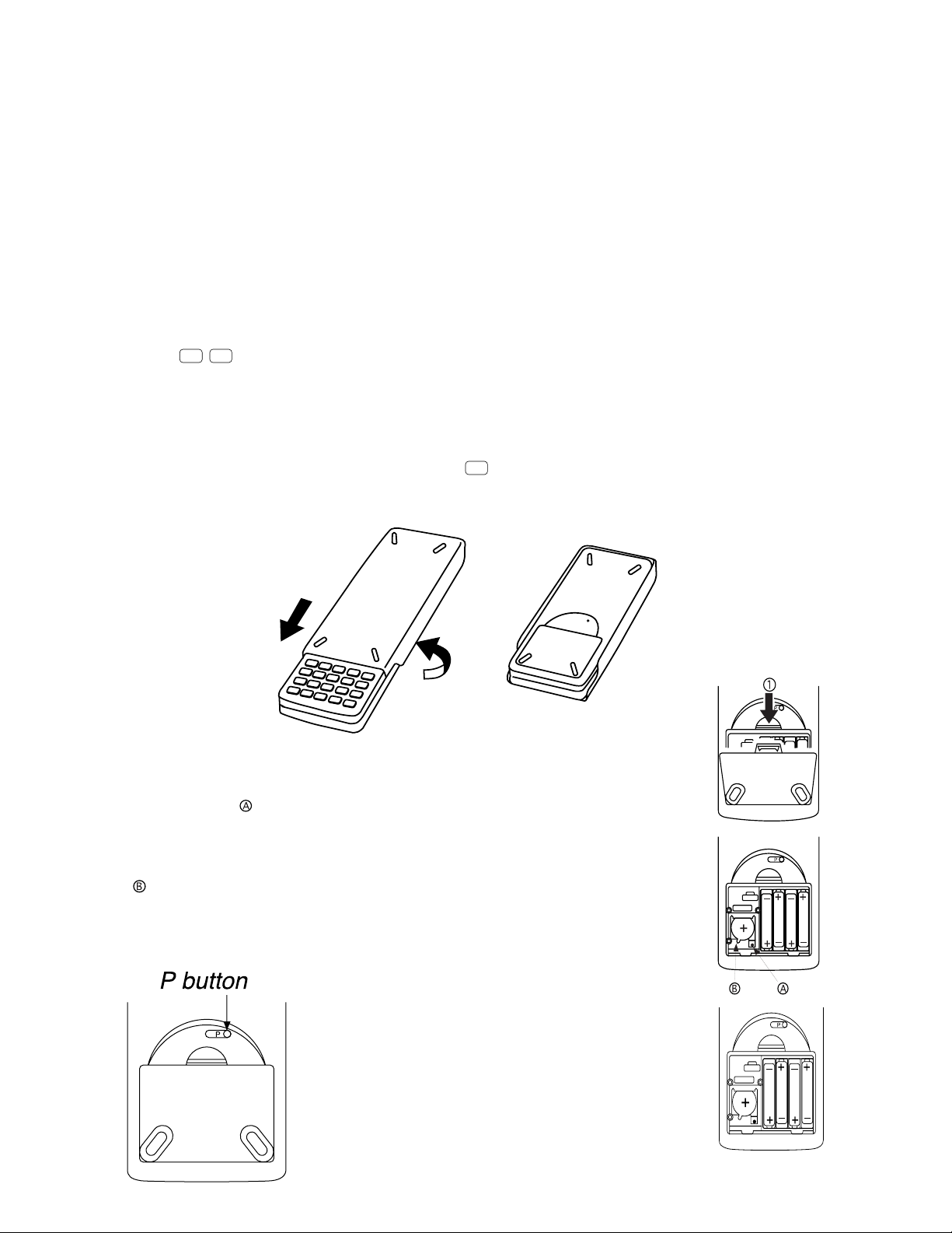
• To replace the memory back up battery
* Before replacing the memory back up battery, turn on the unit and check to see if the “Low battery!”
message appears on the display. If it does, replace the main power supply batteries before replacing the
back up power supply battery.
* Never remove the main power supply and the memory back up batteries from the unit at the same time.
* Be sure to replace the back up power supply battery at least once 2 years, regardless of how much you
use the unit during that time. Failure to do so can cause data in memory to be deleted.
SHIFT
1. Press
OFF
to turn the calculator off.
Warning!
* Be sure to turn the unit off before replacing batteries. Replacing batteries with power on will cause data
in memory to be deleted.
2. Making sure that you do not accidently press the
AC/ON
key, slide the case onto the calculator and then turn
the calculator over.
3. Slide the back cover from the unit by pulling with your finger at the point marked 1.
4. Remove screw on the back of the calculator, and remove the back up battery
compartment cover.
5. Insert a thin, pointed non-metal object (such as a tooth pick) into the hole marked
and remove the old battery.
6. Wipe off the surfaces of a new battery with a soft, dry cloth. Load it into the
calculator so that its positive ( + ) side is facing up.
— 8 —
Page 9
EXE
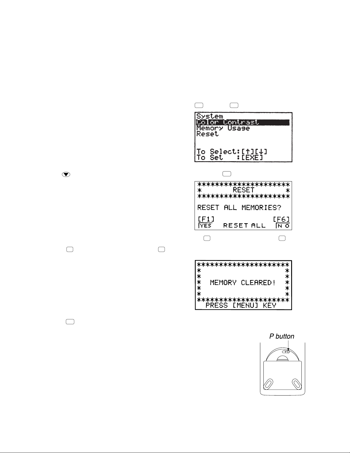
3. RESET OPERATION
Warning!
The procedure described here clears all memory contents. Never perform this operation unless you want to
totally clear the memory of the calculator. If you need the data currently stored in memory, be sure to write
it down somewhere before performing the RESET operation.
• To reset the calculator
1. Highlight the SYS icon on the main menu and then press
EXE
, or press
tan
F
.
2. Use to move the highlighting down to “RESET” and then press
F1 F6
3. Press
4. Press
F1
(YES) to reset the calculator or
MENU
.
F6
(NO) to abort the operation without resetting anything.
.
• If the display appears too dark or dim after you reset the calculator, adjust the tint.
• If the calculator stops operating correctly for some reason, use a thin, pointed
object to press the P button on the back of the calculator. This should make the
RESET screen appear on the display. Perform the procedure to complete the
RESET operation.
• Pressing the P button while an internal calculation is being performed will cause
all data in memory to be deleted.
— 9 —
Page 10
4. DATA COMMUNICATIONS
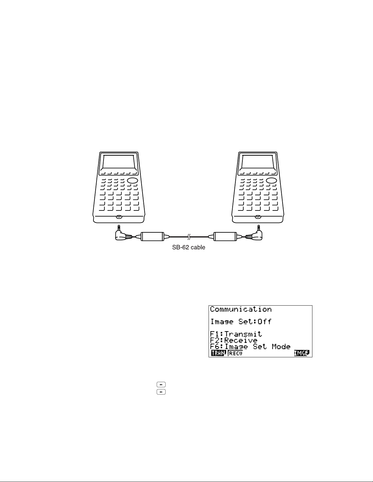
4-1. Connecting Two Units
The following procedure describes how to connect two units with an optional SB-62 connecting cable for
transfer of programs between them.
To connect two units
1. Check to make sure that the power of both units is off.
2. Remove the covers from the connectors of the two units.
• Be sure you keep the connector covers in a safe place so you can replace them after you finish your data
communications.
3. Connect the two units using the SB-62 cable.
• Keep the connectors covered when you are not using them.
4-2. Before Starting Data Communications
In the Main Menu, select the LINK icon and enter the LINK Mode. The following data communication main
menu appears on the display. (Select the LINK icon, then press EXE button.)
Image Set:............Indicates the status of the graphic image send features.
Off: Graphic images not sent.
Monochrome: Pressing
Color: Pressing
•{TRAN}/{RECV} ........ Menu of {send settings}/{receive settings}
•{IMGE} .........{menu of graphic image transfer settings}
Communications parameters are fixed at the following settings.
• Speed (BPS): 9600 bits per second
• Parity (PARITY): NONE
sends graphic images in monochrome.
F D
sends graphic images in color.
F D
— 10 —
Page 11

4-3. Performing Data Transfer Operation
Connect the two units and then perform the following procedures.
Receiving unit
To set up the calculator to receive data, press
displayed.
The calculator enters a data receive standby mode and waits for data to arrive. Actual data receive starts as
soon as data is sent from the sending unit.
Sending unit
To set up the calculator to send data, press
displayed.
F2
(RECV) while the data communication Main Menu is
F1
(TRAN) while the data communication Main Menu is
Press the function key that corresponds to the type of data you want to send.
•{SEL}.......{selects data items and sends them}
•{CRNT}....{selects data items from among previously selected data items and sends them}
•{BACK} ...{all memory contents, including mode settings}
• To send selected data items
Press
F1
(SEL) or F2(CRNT) to display a data item selection screen.
Data items
• {SEL} .......{selects data item where cursor is located}
• {TRAN}....{sends selected data items}
Use the and cursor keys to move the cursor to the data item you want to select and press
to select it. Currently selected data items are marked with “ ”. Pressing
▲
F6
(TRAN) sends all the selected
data items.
• To deselect a data item, move the cursor to it and press
F1
(SEL) again.
F1
(SEL)
Only items that contain data appear on the data item selection screen. If there are too many data items to fit
on a single screen, the list scrolls when you move the cursor to the bottom line of the items on the screen.
The following are the types of data items that can be sent.
— 11 —
Page 12
Data Item
Program
Mat n
List n
File n
Y=Data
Contents
Program contents
Matrix memory (A to Z) contents
List memory (1 to 6) contents
List file memory (1 to 6) contents
Graph expressions, graph write/non-write
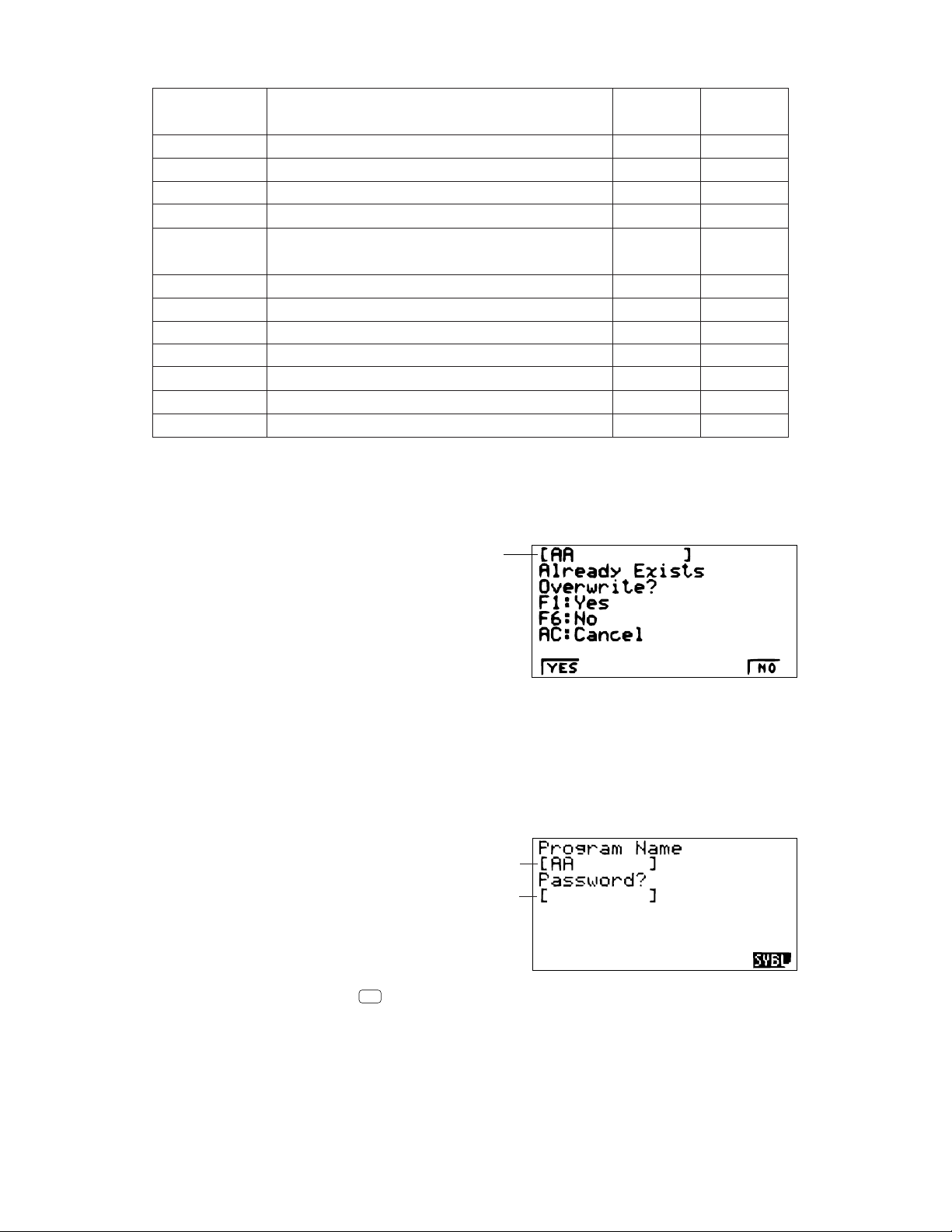
Overwrite
Check*
Yes
Yes
Yes
Yes
No
Password
1
Check*
Yes
2
status, View Window contents, zoom factors
G-Mem n
V-Win n
Picture n
DynaMem
Equation
Variable
F-Mem
Graph memory (1 to 6) contents
View Window memory contents
Picture (graph) memory (1 to 6) data
Dynamic Graph functions
Equation calculation coefficient values
Variable assignments
Function memory (1 to 6) contents
Yes
No
No
Yes
No
No
No
*1No overwrite check: If the receiving unit already contains the same type of data, the existing data is
overwritten with the new data.
With overwrite check If the receiving unit already contains the same type of data, a message appears
to ask if the existing data should be overwritten with the new data.
Data item name
• {YES} ......{replaces the receiving unit's existing data with the new data}
• {NO} ........{skips to next data item}
*2With password check: If a file is password protected, a message appears asking for input of the
password.
Name of password protected file
• {SYBL} ....{symbol input}
After inputting the password, press
Password input field
EXE
.
— 12 —
Page 13

• To execute a send operation
After selecting the data items to send, press
execute the send operation.
• {YES}.....{sends data}
• {NO}.......{returns to data selection screen}
F6
(TRAN). A message appears to confirm that you want to
Press
• You can interrupt a data operation at any time by pressing
F1
(YES) to send the data.
AC
.
The following shows what the displays of the sending and receiving units look like after the data communication
operation is complete.
Sending Unit Receiving Unit
Press
AC
to return to the data communication Main Menu.
• To send backup data
This operation allows you to send all memory contents, including mode settings. While the send data type
selection menu is on the screen, press
Press
F6
(TRAN) to start the send operation.
F6
(BACK), and the back up send menu shown below appears.
— 13 —
Page 14

The following shows what the displays of the sending and receiving units look like after the data communication
AC
AC
operation is complete.
Sending Unit Receiving Unit
Press
AC
to return to the data communication Main Menu.
• Data can become corrupted, necessitating a RESET of the receiving unit, should the connecting cable
become disconnected during data transfer. Make sure that the cable is securely connected to both units
before performing any data communication operation.
4-4. Data Communication Precautions
Note the following precautions whenever you perform data communications.
• An error occurs whenever you try to send data to a receiving unit that is not yet standing by to receive data.
When this happens, press
data.
• An error occurs whenever the receiving unit does not receive any data approximately six minutes after it
is set up to receive data. When this happens, press
• An error occurs during data communications if the cable becomes disconnected, if the parameters of the
two units do not match, or if any other communications problem occurs. When this happens, press
clear the error and correct the problem before trying data communications again. If data communications
are interrupted by
AC
key operation or an error, any data successfully received up the interruption will be
in the memory of the receiving unit.
• An error occurs if the receiving unit memory becomes full during data communications. When this happens,
press
AC
to clear the error and delete unneeded data from the receiving unit to make room for the new
data, and then try again.
to clear the error and try again,after setting up the receiving unit to receive
to clear the error.
AC
to
• To send picture (graph) memory data, the receiving unit need 1-kbyte of memory for use as a work area
in addition to the data being received.
— 14 —
Page 15

+–
ORANGE
BLUE
GREEN
CONTRAST
COLOR
O B G
INIT
IN•A
✽✽✽✽✽✽✽✽✽✽✽✽✽✽✽✽✽✽✽✽
✽
✽✽✽✽✽✽✽✽✽✽✽✽✽✽✽✽✽✽✽✽
✽
MEMORY CLEARED!
PRESS [MENU] KEY
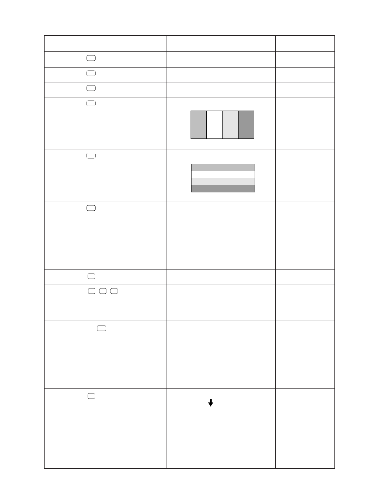
5. OPERATION CHECK
❋ Performing this operation check, the data stored in this calculator is deleted. If you want not to delete these
data, save these data to another CFX-9970G.
STEP
1
2
3
4
OPERATION
Press P button on the back of
the unit using any thin and pointed
object.
Press F1button.
Press
Press
SHIFT
AC/ON
ingF6 and
AC/ON
, then
button.
button while press-
ab/c
buttons at the
same time.
DISPLAY
✽✽✽✽✽✽✽✽✽✽✽✽✽✽✽✽✽✽✽✽
✽
RESET
✽✽✽✽✽✽✽✽✽✽✽✽✽✽✽✽✽✽✽✽
RESET ALL MEMORIES?
[F1] [F6]
RESET ALLYES NO
OFF (No display)
<<<ZX936 TEST MODE>>>
4MbitROM ✼/✼✼
8MbitROM ✼/✼✼
1.Cnt 6.ROM
2.LCD 7.RAM
3.KEY 8.CYC
4.DET 9.3020
5.TRS 0.Rst
NOTE
Reset
✽
TEST mode menu
Press1, then
5
Press
6
7
Press 2 button.
8
Press
9
Press
EXIT
EXE
EXE
button.
button.
button.
10
Press
EXE
button.
EXE
button.
The contrast
changes automatically.
Min→Max→default
<<<ZX936 TEST MODE>>>
TEST mode menu
4MbitROM ✼/✼✼
8MbitROM ✼/✼✼
1.Cnt 6.ROM
2.LCD 7.RAM
3.KEY 8.CYC
4.DET 9.3020
5.TRS 0.Rst
Frame is displayed
No color, no display
All orange dots are displayed
All green dots are displayed
Check for display
Check for display
Check for display
Check for display
— 15 —
Page 16
STEP
OPERATION
DISPLAY
NOTE
11
12
13
14
15
16
Press
Press
Press
Press
Press
Press
EXE
EXE
EXE
EXE
EXE
EXE
button.
button.
button.
button.
button.
button.
All blue dots are displayed
Checkers are displayed
Reverse checkers are displayed
Blue
No color
Orange
Green
Blue
No color
Orange
Green
<<<ZX936 TEST MODE>>>
4MbitROM ✼/✼✼
8MbitROM ✼/✼✼
1.Cnt 6.ROM
2.LCD 7.RAM
3.KEY 8.CYC
4.DET 9.3020
5.TRS 0.Rst
Check for display
Check for display
Check for display
Check four colors.
If the colors do not
appear accurately,
perform the adjustment mentioned in
page 5.
Check four colors
TEST mode menu
Press 3 button.
17
Press
18
Press .....
19
Press 6button.
20
F1 F2
EXE
F3
..... buttons.
buttons.
Trace
Trace,Zoom, V-Window.....
<<<ZX936 TEST MODE>>>
4MbitROM ✼/✼✼
8MbitROM ✼/✼✼
1.Cnt 6.ROM
2.LCD 7.RAM
3.KEY 8.CYC
4.DET 9.3020
5.TRS 0.Rst
3017 4MbitROM ✼/✼✼
3017 4MbitROM ✼/✼✼
✼✼✼ ROM OK✼✼✼
CALC SUM= ✼✼✼✼✼✼
READ SUN= ✼✼✼✼✼✼
3020 8MbitROM ✼/✼✼
✼✼✼ ROM OK✼✼✼
CALC SUM= ✼✼✼✼✼✼
READ SUN= ✼✼✼✼✼✼
— 16 —
Check for keys
Check for keys.
Push the key sequentially indicated
on the display.
TEST mode menu
ROM check
The display shown
to the left appears
about 6 seconds
later.
Page 17

STEP
6
OPERATION
DISPLAY
NOTE
21
Press
Press 7 button.
22
Press
23
EXE
EXE
button.
button.
<<<ZX936 TEST MODE>>>
4MbitROM ✼/✼✼
8MbitROM ✼/✼✼
1.Cnt 6.ROM
2.LCD 7.RAM
3.KEY 8.CYC
4.DET 9.3020
5.TRS 0.Rst
RAMSIZE 128K byte
RAMSIZE 128K byte
RAM OK
RAMaddress
FFFF
RAMwrite
AA
RAMread
AA
<<<ZX936 TEST MODE>>>
4MbitROM ✼/✼✼
8MbitROM ✼/✼✼
1.Cnt 6.ROM
2.LCD 7.RAM
3.KEY 8.CYC
4.DET 9.3020
5.TRS 0.Rst
TEST mode menu
RAM check
The display shown
to the left appears
about 10 seconds
later.
TEST mode menu
24
Press 0 button.
Press F1button.
25
26
Press
Press
27
MENU
SHIFT
button.
, then
AC/ON
button.
✼✼✼✼✼✼✼✼✼✼✼✼✼✼✼✼✼✼✼
✼
RESET
Reset
✼
✼✼✼✼✼✼✼✼✼✼✼✼✼✼✼✼✼✼✼
RESET ALL MEMORIES ?
[ F1 ]
[ F
N ORESET ALLYES
✼✼✼✼✼✼✼✼✼✼✼✼✼✼✼✼✼✼✼
✼
✼
✼
MEMORY CLEARED !
✼
✼
✼
✼
✼
✼
✼
✼✼✼✼✼✼✼✼✼✼✼✼✼✼✼✼✼✼✼
PRESS [MENU] KEY
MAIN MENU.
OFF (No display) END
— 17 —
Page 18

6. TO SAVE THE DATA
CFX-9970G can transfer the customer's data to another CFX-9970G unit with memory protection only when
replacing the LCD or the outer case.
To connect the CSF Unit to another CSF Unit
1.Make sure that the power of both units are switched off.
2.Remove the covers from the data communications jacks on the two CSF Units.
3.Connect the two units using the SB-62 cable.
STEP
OPERATION
g
Press button
while pressing
F6
and button
at the same time.
Press button.
1
Press button.
2
3
Press button.
4
AC/ON
ab/c
5
1
1
A uint
A unit B unit
OPERATION
<<<
ZX936 TEST MODE
4MbitROM ✼/ ✼✼
8MbitROM ✼/ ✼✼
1.Cnt 6.RON
2.LCD 7.RAM
3.KEY 8.CYC
4.DET 9.3020
5.TRS 0.Rst
TRANSMIT Check
1.COM Check
2.VCCI Spec Test
0.Self
1.Send
2.Receive
SENDING ...
OPERATION
>>>
Press button
AC/ON
while pressing
F6
and
buttons at the
same time.
Press button.
Press button.
Press button.
5
1
2
ab/c
<<<
4MbitROM ✼/ ✼✼
8MbitROM ✼/ ✼✼
1.Cnt 6.RON
2.LCD 7.RAM
3.KEY 8.CYC
4.DET 9.3020
5.TRS 0.Rst
0.Self
1.Send
2.Receive
B uint
OPERATION
ZX936 TEST MODE
TRANSMIT Check
1.COM Check
2.VCCI Spec Test
WAITING ...
RECEIVING ...
>>>
TEST mode
NOTE
menu
COM END
COM OK
— 18 —
Page 19

1
STEP
OPERATION
g
Press button.
5
Press button.
6
7
EXE
2
A unit B unit
OPERATION
0.Self
1.Send
2.Receive
Press button.
EXE
0.Self
1.Send
2.Receive
WAITING ...
RECEIVING ...
Press button.
SENDING ...
OPERATIONOPERATION
NOTE
Press button.
8
Press button.
9
Take the steps as
10
same as the end
of 5.OPERATION
CEHCK to end
this check.
EXE
AC/ON
COM OK
0.Self
1.Send
2.Receive
<<<
ZX936 TEST MODE
4MbitROM ✼/ ✼✼
8MbitROM ✼/ ✼✼
1.Cnt 6.RON
2.LCD 7.RAM
3.KEY 8.CYC
4.DET 9.3020
5.TRS 0.Rst
EXE
Press button.
>>>
AC/ON
Press button.
Take the steps as
same as the end
of 5.OPERATION
CEHCK to end
this check.
COM END
0.Self
1.Send
2.Receive
<<<
ZX936 TEST MODE
4MbitROM ✼/ ✼✼
8MbitROM ✼/ ✼✼
1.Cnt 6.RON
2.LCD 7.RAM
3.KEY 8.CYC
4.DET 9.3020
5.TRS 0.Rst
>>>
TEST mode
menu
— 19 —
Page 20

7. TROUBLESHOOTING
SYMPTOM CAUSE SOLUTION
Intermittent display
No display at all
Erratic display
Dirt or poor contact on battery
Poor contact on power switch
Poor connection on PC joiner
Poor soldering on LSI, capacitor, or resistor
Weak battery
Dirt or poor contact on battery
Poor contact on power switch
Poor connection on PC joiner
Defective LSI, capacitor, or resistor
Poor contact between LCD and PCB
Poor soldering on LSI
Clean or adjust pressure of
contact
Clean or replace power
switch
Resolder or replace
Resolder
Replace battery
Clean or adjust pressure of
contact
Clean or replace power
switch
Resolder or replace
Replace
Replace the heat seal
Resolder or replace display
PCB ass'y
Certain key does not
function
All keys do not function
Heavy key motion
Dirt on key contact
Heavy key motion
Poor soldering on LSI
Defective LSI, capacitor, or resistor
Constant contact is made on a certain key
Defective LSI, capacitor, or resistor
Dirt or scratch on the key
Clean or replace contact
Clean or replace the key
Resolder
Replace
Separate the contact
Replace
Clean or replace the key
— 20 —
Page 21

About 3 seconds later
8. OPERATION PROBLEMS
If you keep having problems when you are trying to perform operations, try the following before assuming that
there is something wrong with the calculator.
• Get the Calculator Back to its Original Mode Settings
1. In the Main Menu, select the RUN icon and press
SHIFT
2. Press
3. Highlight "Angle" and press
4. Highlight "Display" and press
SET UP
to display the set up screen.
F2
(Rad).
F3
(Norm) to select the exponential display range (Norm 1 or Norm 2) that
EXE
.
you want to use.
5. Now enter the correct mode and perform your calculation again, monitoring the results on the display.
• In Case of Hang Up
• Should the unit hang up and stop responding to input from the keyboard, press the P button on the back
of the calculator to reset the memory. Note, however, that this clears all the data in calculator memory.
• Low Battery Message
The low battery message apppears whenever you press
AC/ON
to turn power on or
MENU
to display the Main
Menu while the main battery power is below a certain level.
AC/ONorMENU
If you continue using the calculator without replacing batteries, power will automatically turn off to protect
memory contents. Once this happens, you will not be able to turn power back on, and there is the danger that
memory contents will be corrupted or lost entirely.
• You will not be able to perform data communications operations once the low battery message appears.
— 21 —
Page 22

9. ERROR MESSAGE
Message
Syn ERROR
Ma ERROR
Meaning
1 Calculation formula contains an error.
2 Formula in a program contains an error.
1 Calculation result exceeds calculation
range.
2 Calculation is outside the input range of
a function.
3 Illogical operation (division by zero, etc.)
4 Poor precision in Σ calculation results.
5 Poor precision in differential calculation
results.
6 Poor precision in integration calculation
results.
7 Cannot find results of equation calcula
tions.
8 Attempt to use approx with an expres
sion that generates an error unique to
the ALGBR Mode.
Countermeasure
1 Use or to display the point
where the error was generated and correct it.
2 Use or to display the point
where the error was generated and then
correct the program.
1234
Check the input numeric value and correct it.
When using memories, check that the
numeric values stored in memories are
correct.
5 Try using a smaller value for ∆x (x incre-
ment/decrement).
6 Try changing the tolerance “tol” when
using Gauss-Kronrod Rule or the number of divisions “n” when using Simpson’s
Rule to another value.
7 Check the coefficients of the equation.
8 Change the input expression.
Go ERROR
Ne ERROR
1 No corresponding Lbl n for Goto n.
2 No program stored in program area Prog
“file name”.
• Nesting of subroutines by Prog “file name”
exceeds 10 levels.
1 Correctly input a Lbl n to correspond to
the Goto n, or delete the Goto n if not
required.
2 Store a program in program area Prog
“file name”, or delete the Prog “file name”
if not required.
• Ensure that Prog “file name” is not used to
return from subroutines to main routine. If
used, delete any unnecessary Prog “file
name”.
• Trace the subroutine jump destinations
and ensure that no jumps are made back
to the original program area. Ensure that
returns are made correctly.
— 22 —
Page 23

Message
MeaningMeaning
Countermeasure
Stk ERROR
Mem ERROR
Arg ERROR
• Execution of calculations that exceed the
capacity of the stack for numeric values or
stack for commands.
• Not enough memory to input a function
into function memory.
• Not enough memory to create a matrix
using the specified dimension.
• Not enough memory to hold matrix calculation result.
• Not enough memory to store data in list
function.
• Not enough memory to input coefficient
for equation.
• Not enough memory to hold equation calculation result.
• Not enough memory to hold function input
in the Graph Mode for graph drawing.
• Not enough memory to hold function input
in the DYNA Mode for graph drawing.
• Not enough memory to hold function or
recursion input.
• Incorrect argument specification for a
command that requires an argument.
•Simplify the formulas to keep stacks withi
10 levels for the numeric values and 26
levels for the commands.
• Divide the formula into two or more parts.
• Keep the number of variables you use for
the operation within the number of variables currently available.
• Simplify the data you are trying to store to
keep it within the available memory capacity.
• Delete no longer needed data to make
room for the new data.
• Correct the argument.
• Lbl n, Goto n: n = integer from 0 through 9.
Dim ERROR
Com ERROR
TRANSMIT
ERROR !
RECEIVE
ERROR !
MEMORY
FULL !
• Illegal dimension or list used during matrix
calculations.
• Problem with cable connection or parameter setting during program data communications.
• Problem with cable connection or parameter setting during data communications.
• Problem with cable connection or parameter setting during data communications.
• Memory of receiving unit became full
during program data communications.
• Check matrix or list dimension.
• Check cable connection.
• Check cable connection.
• Check cable connection.
• Delete some data stored in the receiving
unit and try again.
— 23 —
Page 24

Message
MeaningMeaning
Countermeasure
Undefined • No solution exists for the operation being • Change the input expression.
performed in the ALGBR Mode.
Overflow • The resulf of the operation being perform- • Change the input expression.
ERROR ed in the AKGBR Mode exceds the range
of the calculator.
Domain • An input value in the ALGBR Mode is out- • Change the input expression.
ERROR side the domain of the operation being
performed.
Non-Real • In the ALGBR Mode, only real numbers 1 Change the setting of Answer type
ERROR have been input and the result is complex to “Cplx”.
number while the set up screen’s Answer 2 Change the input expression.
Type item is specified as “Real”.
No Solution • No solution can be obtained in the ALG- 1 Change the setting of Answer type
ERROR BR Mode using the Solve function. to “Cplx”.
2 2 Change the input expression.
— 24 —
Page 25

10. SCHEMATIC DIAGRAMS
Main block-1
P button
To Display drive block
To Key block
To Main block-2
— 25 —
Page 26

Main block-2
To Main block-1
To Memory block
— 26 —
Page 27

Key block
To Main block-1
— 27 —
Page 28
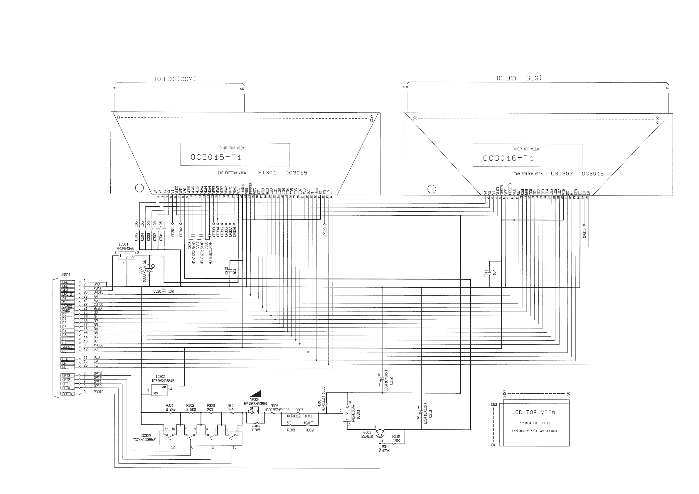
Display drive block
Sub ass'y
Sub ass'y
To Main block-1
Contrast adj.
— 28 —
Page 29

Memory block
( 8M ROM )
To Main block-2
— 29 —
Page 30

11. PARTS LIST
8
1
2
3
14
14
14
14
4
5
7
9
10
11
6
12
13
15
16
26
27
28
29
30
31
32
N Item Code No. Parts Name Specification Q R
COMPONENTS
N 1 6421 0990 CASE/UPPER A140713-2 1 X
N 2 6420 7010 RUBBER/CONTACT A241013-1 1 C
N 3 6421 1000 HARD COVER A140715-2 1 X
N 4 6421 1010 COVER/BATTERY A241009-2 1 C
N 5 6421 1110 CASE/LOWER A140714-2 1 X
6 6419 9840 RUBBER/CONTACT A341594-1 1 C
7 6398 8740 SPRING/BATTERY A412218-1 1 C
8 6386 7470 SPRING/BATTERY A410113-1 2 C
9 6386 7450 SPRING/BATTERY A410112-1 1 C
10 6386 7430 SPRING/BATTERY A310154-1 1 C
N 11 6420 3660 BUTTON A341610-1 1 C
N 12 6421 3090 SPRING A341016-4 1 C
13 6417 3520 SPRING A441675-1 1 C
N 14 6420 7040 RUBBER/FOOT A442718-1 8 X
15 6416 9500 HOLDER/BATTERY A441594-1 1 C
16 6390 0432 CAP A310765B-1 1 C
N 17 6421 1020 BUTTON A211169-5 1 C
N 18 6421 1030 BUTTON A211172-4 1 C
N 19 6421 1040 BUTTON A312937-3 1 C
N 20 6421 1050 BUTTON A211316-12 1 C
N 21 6421 1060 BUTTON A313257-12 1 C
N 22 6421 1070 BUTTON A313257-13 1 C
N 23 6421 1080 BUTTON A313257-14 1 C
N 24 6421 1090 BUTTON A312914-4 1 C
N 25 6421 1100 BUTTON A341741-2 1 C
26 6402 2480 DECORATIVE SCREW A-L163 A412682-1 1 C
N 27 6420 6910 PCB ASSY A241051C*1 1 B
N 28 6420 6920 PCB ASSY A241052B*1 1 B
N 29 6420 6930 PCB ASSY A341804A*1 1 B
N 30 3719 5369 CABLE/JOINT A442842-1 1 C
N 31 6420 6900 LCD ASSY A241053B*1 1 B
N 32 6420 7230 FRAME/INNER CASE A241008-1 1 X
12. EXPLODED VIEW(1/2)
Parts prices will be informed separately by Parts Price List.
Notes: N – New parts Essential
Q – Quantity used per unit Stock recommended
R – Rank Others
R – A :
R – A :
B :
B :
C :
C :
X :
No stock recommended
X :
— 30 —
Page 31

12.EXPLODED VIEW(2/2)
24
23
21
22
17
25
20
18
19
— 31 —
Page 32

8-11-10, Nishi-Shinjuku
Shinjuku-ku, Tokyo 160, Japan
Telephone: 03-3347-4926
MA0900171A Printed in Japan
 Loading...