Cashco DA2 User Manual

INSTALLATION, OPERATION & MAINTENANCE MANUAL (IOM) |
IOM-DA2 |
|
11-13 |
MODEL DA2
DIRECT-ACTING, POSITIVE BIAS DIFFERENTIAL
PRESSURE REDUCING REGULATOR
SECTION I
I. DESCRIPTION AND SCOPE
The Model DA2 is a differential pressure reducing regulator used to control differential pressure between downstream (outlet or P2) pressure and a loading (PLoad) pressure to the spring chamber. Sizes 1/2" (DN15), 3/4" (DN20), 1" (DN25), 1-1/4" (DN32), 1-1/2" (DN40), 2" (DN50), 2-1/2" (DN65), 3" (DN80) and 4" (DN100). With proper trim utilization, the unit is suitable for liquid, gaseous, or steam service. Refer to Technical Bulletin DA2TB for design conditions and selection recommendations.
SECTION II |
|
|
|
II. REFERENCES |
|
|
ABBREVIATIONS |
Refer to Technical Bulletin DA2-TB and DAG-TB for |
CCW |
– |
Counter Clockwise |
technical specifications. |
CW |
– |
Clockwise |
|
ITA |
– |
Inner Trim Assembly |
SECTION III |
|
|
|
III. INSTALLATION |
|
|
|
1.Regulator may be rotated around pipe axis 360 degrees. For ease of maintenance, the recommended position is with the spring chamber (4) upwards. In liquid service it is recommended that the spring chamber (4) be oriented downwards, and that a customer supplied and installed vent valve be provided at the external sensing connection to bleed-off trapped gas/air under the diaphragm.
2.Provide space below, above, and around regulator for removal of parts during maintenance.
3.Install block valves and pressure gauges to provide means for adjustment, operation, bypass, or removal of the regulator. An isolation valve on the loading line is not recommended.
4.An outlet pressure gauge should be located approximately ten pipe diameters downstream, and within sight. A loading pressure (or differential pressure) gauge is recommended.
5.All installations should include a downstream relief device if the inlet pressure could exceed the pressure rating of any downstream equipment or the maximum outlet pressure rating of the unit.
6.Clean the piping of all foreign material including chips, welding scale, oil, grease and dirt before installing the regulator. Strainers are recommended.
7.In placing thread sealant on pipe ends prior to engagement, ensure that excess material is removed and not allowed to enter the regulator upon startup.
8.Flow Direction: Install so the flow direction matches the arrow cast on the body.
9.If the loading pressure is not lowered sufficiently prior to shutting off the process fluid supply, then the diaphragm will be damaged with the standard construction. The startup, shutdown, and emergency operating procedures should be reviewed to ensure that the loading pressure is less than 50% of the Diaphragm Proof Rating (See Table 1) before shutting off the process fluid supply pressure. If the regulator is specified with a fully supported diaphragm, then the diaphragm will withstand a loading pressure equal to the Diaphragm Proof Rating for the fully supported diaphragm.

10.Downstream Sensing Installation Considerations
– Internal or External Sensing:
a.The regulator may be installed with internal or external sensing. Unless otherwise specified, the regulator is supplied by factory with internal sensing. The regulator may be converted in the field to external sensing (see Section VII Maintenance, Paragraph H).
b.Reference DAG-TB, Table DAG-11 for recommendations for applying external pressure sensing.
c. For internal sensing, no external line is required. For external sensing, use an external control line. The line is connected from the port (1/4" NPT) on the side of the body diaphragm flange (see port 5 in Fig. 5) to a pressure tap. The pressure tap should be located a minimum of 10 pipe diameters downstream of the regulator. It is recommended that the downstream pressure tap be located close to the point of use to minimize the adverse affect of variable line losses. A tubing outer diameter of 0.25 inch is adequate for short sensing lines (less than 4 feet). Use 3/8" tubing or 1/4" Sch 40 pipe for sensing lines of 5 to 50 feet.
d.For condensable vapors (i.e. steam) slope the external sensing line downward 2 to 5 degrees to outlet piping to prevent water pockets, which allows the diaphragm chamber to always be self draining. The external sensing line may be sloped upward for liquids or gases.
CAUTION A
The proof test pressure must not exceed the diaphragm and body rating for the regulator.
CAUTION B
Installation of adequate overpressure protection is recommended to protect the regulator from overpressure and all downstream equipment from damage in the event of regulator failure.
A hydrostatic or pneumatic proof test is allowable under the following conditions for the standard diaphragm construction: Uniformly pressurize the valve body inlet, valve body outlet, and loading chamber to the lesser of the Diaphragm Proof Rating or 1.5 times the Outlet Pressure Rating shown on the nameplate. For example, a 1" DA2 with Cast Iron Body and Spring Chamber, Neoprene Diaphragm (BC) has an Outlet Pressure Rating of 400 psig CWP. The lesser pressure of 1.5X 400 psig = 600 psig and the BC diaphragm proof rating of 1250 psig is 600 psig. Therefore, uniformly pressurizing the DA2 to 600 psig is allowable.
Model DA2 & DA7 Differential
Pressure Reducing Regulator
Recommended Piping Schematic for
Differential Pressure Reducing Station
TABLE 1
MAXIMUM DIAPHRAGM RATING * - psig (Barg)
NOTE: The below ratings may be further "derated" by limitations thru the Pressure Equipment Directive (97/23/EC-May '97).
|
BODY SIZE 1/2" - 2" (DN15-50) |
BODY SIZE 3" - 4" (DN80-100) |
||
|
|
|
|
|
DIAPHRAGM |
STD DIAPHRAGM |
**OPT-81 FULL DIAPHRAGM |
STD DIAPHRAGM |
|
MATERIAL |
CONSTRUCTION |
SUPPORT |
CONSTRUCTION |
|
|
P2 MAX |
P2 MAX |
P2 MAX |
|
BC, EPR |
1250 |
1250 |
800 |
|
(86.1) |
(86.1) |
(55.1) |
||
|
||||
|
|
|
|
|
NBR |
450 |
1250 |
300 |
|
(31.0) |
(86.1) |
(20.6) |
||
|
||||
|
|
|
|
|
FKM, FKM+TFE, FK |
700 |
1250 |
550 |
|
(48.2) |
(86.1) |
(37.9) |
||
|
||||
|
|
|
|
|
3-ply (PTFE+FKM+PTFE) |
125 |
125 |
125 |
|
(8.6) |
(8.6) |
(8.6) |
||
|
||||
|
|
|
|
|
METAL |
1500 |
NA |
NA |
|
Be-Cu |
(103) |
|||
|
|
|||
|
|
|
|
|
*Maximum setting of pressure safety device – safety relief valve or rupture disc.
**Not available for CI/CI, BRZ/CI, BRZ/BRZ, BRZ/CS, BRZ/SST, CS/CI & SST/CI constructions. NA = NOT AVAILABLE
2 |
IOM-DA2 |

SECTION IV
IV. PRINCIPLE OF OPERATION
1.Valve plug movements modulate the flow across the valve seat to maintain the outlet pressure (P2) equal to the sum of the differential pressure (∆PDIFF) and the loading pressure (PLoad). The outlet pressure acting on the underside of the diaphragm tends to close the valve plug against the valve seat. The outlet pressure acting on the topside of the diaphragm tends to lift the valve plug off the valve seat. The positive differential setting of the range spring tends to lift the valve plug off the valve seat. The outlet pressure tracks
with changes to the loading pressure. Each one psi increase or decrease in the loading pressure producesarespectiveonepsiincreaseordecrease in the outlet pressure.
2.For a DA2 (single diaphragm) design, a complete diaphragm failure will cause the outlet process fluid to mix with the loading fluid.
SECTION V
V. STARTUP
1.Start with the block valves closed.
2.Relax the range spring by turning the adjusting screw CCW for the DA2 (viewed from above) a minimum of three (3) full revolutions. This reduces the ∆PDIFF (differential) pressure set point.
3.If it is a “hot” piping system, and equipped with a bypass valve, partially open the bypass valve to preheat the system piping and to allow slow expansion of the piping. Check for proper steam trap operation if installed. Closely monitor outlet (downstream) pressure via gauge to ensure not over-pressurizing. NOTE: If no bypass valve is installed, extra caution should be used in starting up a cold system; (i.e. do everything slowly).
4.Crack open the outlet (downstream) block valve.
CAUTION C
Do not walk away and leave a bypassed regulator unattended!
5.Slowly open the inlet (upstream) block valve to about 25% open, observing the outlet (downstream)pressuregauge. Determineifthe regulator is flowing. If not, slowly rotate the DA2 regulator adjusting screw CW (viewed from above) until flow begins. Slightly open the bleeder valve to vent any air as the spring chamber is filling with a liquid loading fluid.
6.Continue to slowly open the inlet (upstream) block valve until fully open.
7.Continue to slowly open the outlet (downstream) block valve, especially when the downstream piping system is not pressurized. If the outlet (downstream) pressure exceeds the desired pressure, close the inlet block valve and go to Step 2. Close bypass valve approximately 25%, and repeat procedure.
8.When flow is established steady enough that the outlet (downstream) block valve is fully open, begin to slowly close the bypass valve if installed.
9.Set the DA2 regulator set point (∆PDIFF) by turning the adjusting screw clockwise (CW) to increase outlet pressure or CCW to reduce outlet pressure. The outlet (P2) pressure under these conditions will approximate the desired differential pressure when loaded with PLoad for the DA2.
10.Pressurize the source of loading (PLoad) pressure and allow to fill the spring chamber cavity. Slightly open the bleeder valve to vent any air as the spring chamber is filling with a liquid loading fluid.
11.Develop system flow and pressure and readjust setpoint as required to obtain desired response. Performance should be analyzed at minimum and maximum flow levels.
12.Install closing cap where applicable. The standard regulator relies on a double o-ring rotary seal (item 34) around the non-rising adjusting screw.
IOM-DA2 |
3 |

SECTION VI
VI. SHUTDOWN
CAUTION D
Loading Pressure should be lowered as described in Section III, paragraph 9 before shutting down the system pressure.
1.To prevent force imbalances and possible diaphragm failure of the standard diaphragm construction, the loading pressure (PLoad) should be lowered until the loading pressure (PLoad) is less than 50% of the diaphragm proof rating for the
standard construction. System sequencing must ensure this occurs.
2.It is recommended that manual operation not be attempted by a bypass valve during a shutdown.
3.When the outlet pressure (P2) has been lowered to 5 - 10 psig, the inlet (upstream) block valve may be closed. The inlet pressure (P1) should then decay to zero psig before the outlet (downstream) block valve is closed.
SECTION VII
VII. MAINTENANCE
A.General:
1.The regulator may be serviced without removing the regulator from pipeline. The regulator is designed with quick-change trim to simplify maintenance.
2.Record the nameplate information to requisition spare parts for the regulator. The information should include: Size, KM Product Code and Serial Number.
3.Refer to Section VIII for recommended spare parts. Only use original equipment parts supplied by Cashco/KM for rebuilding or repairing regulators.
4.Owner should refer to owner's procedures for removal, handling, cleaning and disposal of nonreuseable parts, i.e. gaskets, etc.
NOTE:On regulators originally suplied as Special Cleaning Option-55, -56, or -57, maintenance must include a level of cleanliness equal to Cashco cleaning standards of #S-1134, #S-1542, and #S-1589 respectively. Contact factory for details.
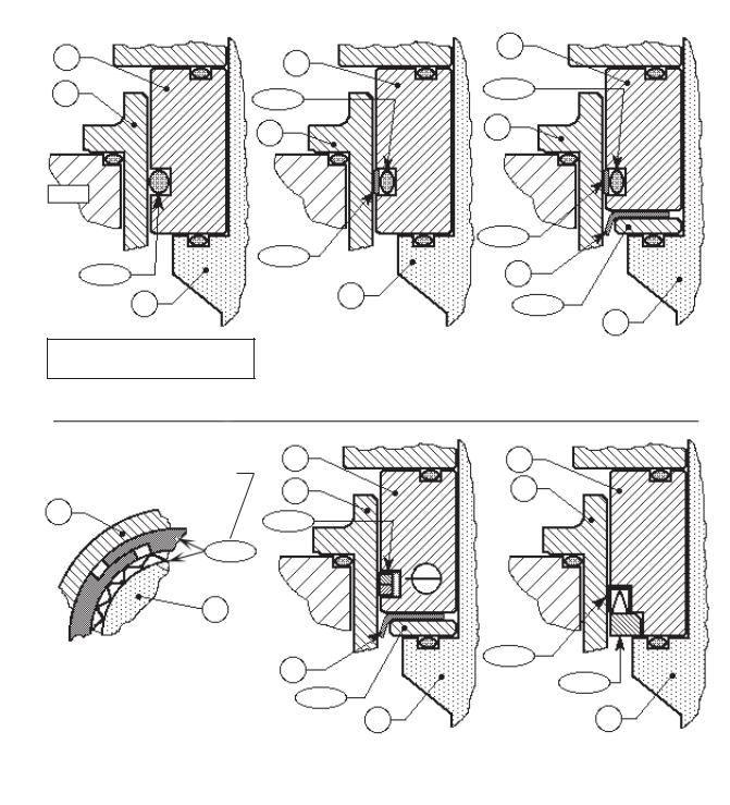
5.The Inner Trim is removed and replaced in the body ( 23) as an assemblage of parts. The Inner Trim Assembly, hereinafter called ITA, consists of the following parts depending on what dynamic sealing system the regulator is using:
Item |
Dynamic |
|
No. |
Seal Type |
Part Description |
13 ..................... |
All .......................... |
Guide Bearing/Piston |
14 ..................... |
All ............................... |
StaticStem Seal † |
14.1 ............... |
All ................... |
Upper Static Stem Seal † |
14.2 ............... |
All ................... |
Middle Static Stem Seal † |
14.3 ............... |
All ................... |
Lower Static Stem Seal † |
15 ..................... |
All ................................ |
Cage O-ring Seal |
16 ................. |
CW,PW.............................................. |
Wiper |
17.1 .............. |
CW,PW................................. |
Wiper Washer |
17.2 ........... |
OR,CP,PR ........ |
Camber Adjusting Washer * |
17.3 ................. |
UC ..................................... |
Seal Retainer |
19 ..................... |
All ................................................... |
Cage |
20 ..................... |
All ........................................... |
Valve Plug |
21 ..................... |
All ............................................ |
Seat Ring |
27 ..................... |
All ............................. |
Dynamic Side Seal |
27.1 ........... |
CP,CW ................................. |
TFE Cap Seal |
27.2 ........... |
CP, CW............................. |
O-ring Energizer |
27.3 .............. |
UC .......... |
U-Cup Seal w/Metal Energizer |
27.4 .............. |
OR ....................................... |
O-Ring Seal |
27.5............ |
PR,PW..... |
Piston Ring Seal w/Metal Energizer |
* Metal Diaphragm Only.
† Comp. Diaphragm Only.
A detailed view of the dynamic side seal parts is shown in Figure 1 on the next page.
WARNING 1
SYSTEM UNDER PRESSURE. Prior to performing any maintenance, isolate the regulator from the system and relieve all pressure. Failure to do so could result in personal injury.*
* Includes external sensing connection if applicable.
4 |
IOM-DA2 |

13 |
|
13 |
13 |
|
|
|
|
|
19 |
27.2 |
27.2 |
|
||
|
|
|
|
19 |
19 |
|
|
|
BODY |
|
|
27.4
20
Type OR — O-Ring
Dynamic Seal
Piston Rings (2) w/Metal Energizer
19
27.5
13
SECTION "A"
27.1
27.1
|
16 |
|
20 |
17.1 |
|
|
||
|
20 |
|
|
|
|
Type CP— TFE Cap |
|
Type CW — TFE Cap |
Dynamic Seal |
|
Dynamic Seal + Wiper |
|
|
|
13 |
13 |
19 |
19 |
27.5
27.3 |
|
|
||||
16 |
|
|
|
|
17.3 |
|
17.1 |
|
|
|
|||
|
|
|
|
|
||
20 |
|
|
|
20 |
||
|
|
|
|
|
||
|
Type PW — PRA Dynamic |
|
|
Type UC — U-Cup |
||
|
|
|
|
|
|
Dynamic Seal |
|
Seal + Wiper |
|
|
|||
|
|
|
|
|
|
|
|
|
|
|
|
|
|
Figure 1: Dynamic Side Seals
IOM-DA2 |
5 |
 Loading...