

INSTALLATION, OPERATION & MAIN TE NANCE MANUAL (IOM)
IOM-123-BASIC
MODEL 123 — BASIC
BACK PRESSURE / RELIEF REGULATOR
SECTION I
I. DESCRIPTION AND SCOPE
The Model 123 is a back pressure relief regulator used to control upstream (inlet or P1) pressure. Sizes are 1/2",
3/4", 1", 1-1/2" and 2" (DN15, 20, 25, 40 and 50). With proper trim utilization, the unit is suitable for liquid, gaseous,
or steam service. Refer to Technical Bulletin 123-TB for design conditions and se lec tion recommendations.
CAUTION A
This is not a safety device and must not be sub sti tut ed for a code approved
pres sure safety relief valve or rupture disc.
SECTION II
12-13
II. INSTALLATION
CAUTION B
For welded installations, all internal trim parts, seals
and diaphragm(s) must be removed from reg u la tor
body prior to welding into pipeline. The heat of
fusion welding will dam age non-metallic parts if
not re moved. NOTE: This does not apply to units
equipped with extended pipe nip ples.
1. An inlet block valve should always be in stalled.
2. If service application is continuous such that
shut down is not readily accomplished, it is rec om mended that an inlet block valve, outlet block
valve, and a manual bypass valve be in stalled.
3. Pipe unions should be installed to allow removal
from piping.
4. An inlet pressure gauge should be lo cated ap proxi mately ten pipe diameters upstream and within
sight. An outlet pres sure gauge is optional.
5. All installations should include an upstream relief
de vice if the inlet pressure could exceed the pressure rating of any equipment or the maximum inlet
pressure rating of the unit.
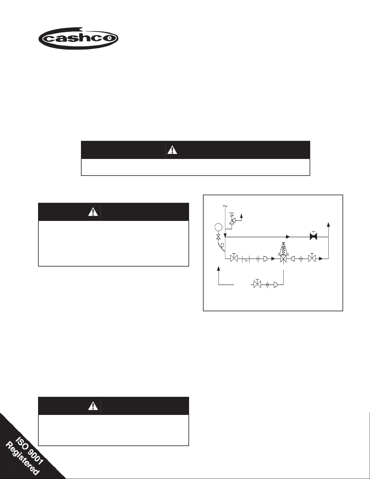
CAUTION C
Supply @ P
P
1
System
Demand
SRV
1
Discharge
Model 123-33
BP/Relief
Regulator
P
2
Bypass
Recommended Piping Schematic for
Back Pressure/Relief Station
6. Clean the piping of all foreign material in clud ing
chips, welding scale, oil, grease and dirt before in stall ing the valve. Strain ers are rec om mended.
7. In placing thread sealant on pipe ends prior to
en gage ment, ensure that excess material is re moved and not allowed to enter the regulator upon
startup.
8. Flow Direction: Install so the fl ow direction match-
es the arrow cast on the body. The body has an
angle con fi g u ra tion with a side inlet and bottom
outlet.
Installation of adequate overpressure pro tec tion
is recommended to pro tect the reg u la tor and all
downstream equip ment from dam age in the event
of reg u la tor failure.
9. Regulator may be installed in a vertical or hor i zon tal pipe. If it is a steam system, ensure the
piping is properly trapped and oriented.

10.A. Basic Regulator- (See Figure 1): Regulator may be
rotated around the pipe axis 360°. Rec om mend ed
po si tions are with spring cham ber ver ti cal upwards,
or hori zon tal. Orient such that the spring chamber
vent hole does not collect rain wa ter or debris.
10.B. Cryogenic Regulator -
Option-5 or -36 (See Fig ure 2):
a. Recommended installation is with spring cham-
ber hang ing vertical downward below the body.
This method allows water to drain; i.e. rain water.
b. Recommend inert purge gas to spring cham ber
through vent hole and out drain hole.
III. PRINCIPLE OF OPERATION
1. Movement occurs as pressure variations reg is ter on
the diaphragm. The registering pressure is the inlet,
P
or upstream pressure. The range spring opposes
1
dia phragm move ment. As inlet pressure drops, the
WARNING 1
The maximum inlet pressure is equal to 1.5 times the
larger number of the stated range spring on the name plate, and is the recommended “upper operative limit” for
the sensing diaphragm. Higher pressures could dam age
the diaphragm. (Field hydro static tests fre quent ly de stroy
diaphragms. DO NOT HYDRO STATIC TEST THROUGH AN
IN STALLED UNIT; ISO LATE FROM TEST.)
11. Regulators are not to be direct buried un der ground.
12. For insulated piping systems, rec om men da tion is to
not in su late reg u la tor.
SECTION III
range spring pushes the dia phragm down, closing
the port; as inlet pressure in creases, the dia phragm
pushes up and the port opens.
2. A complete diaphragm failure may cause the regulator to fail closed.
IV. STARTUP
1. Start with the block valves closed. A bypass valve
may be used to maintain inlet pressure in the
up stream system without chang ing the following
steps.
2. Relax the range spring by turning the adjusting
screw counterclockwise (CCW) a minimum of three
(3) full revo lu tions. This reduces the inlet (upstream)
pres sure setpoint.
3. If it is a “hot” piping system, and equipped with a
bypass valve, slowly open the bypass valve to preheat the system piping and to allow slow ex pan sion
of the piping. Ensure proper steam trap operation
if in stalled. Closely mon i tor inlet (up stream) pres sure, via gauge, to assure not over-pres sur iz ing.
NOTE: If no bypass valve is in stalled, extra caution
should be used in starting up a cold system; i.e. do
ev ery thing slowly.
4. Crack open the inlet (upstream) block valve.
5. Slowly open the outlet (downstream) block valve
ob serv ing the inlet (upstream) pressure gauge. De ter mine if the regulator is fl owing. If not, slowly ro-
tate the regulator adjusting screw counter clock wise
(CCW) until fl ow be gins.
6. Continue to slowly open the outlet (down stream)
block valve until fully open.
SECTION IV
7. Observing the inlet (upstream) pressure gauge,
ro tate the ad just ing screw clockwise (CW) slowly
until the inlet pressure begins to rise. Rotate CW
until the desired setpoint is reached.
8. Continue to slowly open the inlet (upstream) block
valve. If the inlet (upstream) pressure ex ceeds
the desired set point pressure, rotate the adjusting
screw CCW until the pressure decreases.
9. When fl ow is established steady enough that both
the outlet and inlet block valves are fully open, begin
to slowly close the bypass valve if installed.
10. Develop system fl ow to a level near its expected nor-
mal rate, and reset the regu la tor set point by turning
the ad just ing screw CW to increase inlet pressure,
or CCW to reduce inlet pressure.
11. Reduce system fl ow to a minimum level and observe
set point. Inlet pressure will rise from the setpoint
of Step 9. (Ensure that this rise does not exceed
the stated upper limit of the range spring by greater
than 50%, i.e. 30 - 80 psig (2.1 - 5.5 Barg) range
spring, at maximum fl ow the inlet pressure should
not ex ceed 1.5 x 80 psig (5.6 Barg), or 120 psig (8.3
Barg). If it does, consult factory.)
12. Increase fl ow to maximum level if possible. Inlet
(up stream or P
) pressure should fall off. Readjust
1
setpoint as necessary at the normal fl ow rate.
2
IOM-123-BASIC
V. SHUTDOWN
SECTION V
1. On systems with a bypass valve, and where sys tem pres sure is to be maintained as the regu la tor
is shut down, slowly open the bypass valve while
closing the inlet (upstream) block valve. Fully
close the inlet (up stream) block valve. (When on
bypass, the system pressure must be con stant ly
observed and manually reg u lat ed. Close the outlet (down stream) block valve.
SECTION VI
VI. MAINTENANCE
WARNING 2
SYSTEM UN DER PRES SURE. Prior to performing
any maintenance, isolate the reg u la tor from the system and relieve all pressure. Failure to do so could
result in per son al injury.
A. General:
1. Maintenance procedures hereinafter are
based upon removal of the regulator unit from
the pipe line where installed.
CAUTION D
Do not walk away and leave a bypassed reg u la tor
un at tend ed.
2. If the reg u la tor and system are both to be shut down, slowly close the inlet (upstream) block
valve. Close the outlet (downstream) valve only
if regu la tor re moval is required.
6. Remove diaphragm sub-assembly con sist ing
of the diaphragm(s) (3), pressure plate (2),
lock washer (13), piston (14), piston nut (6)
and pusher plate gasket (5). NOTE: Refer to
the quantity of di a phragms (12) in cor po rated
per the bill of ma te ri als listing. De pend ing
on inlet pressure level, mul tiple metal dia phragms may be “stacked”.
7. Loosen the piston nut (6) and separate all
parts (3, 5, 13, 14 & 20) of the diaphragm
sub-assembly. Clean the pusher plate gasket
(5) sur face if the piston (14) is to be reused.
2. Owner should refer to owner's procedures for
re mov al, handling, cleaning and disposal of
non reuseable parts, i.e. gaskets, etc.
3. Refer to Figure 1 for basic regulator, Figure
2 for cryogenic regulator, and Figure 3 for
blow-up of the com po si tion seat trim.
B. Diaphragm Replacement:
WARNING 3
SPRING UNDER COMPRESSION. Prior to re mov ing spring chamber, relieve spring compression
by removing the ad just ing screw. Failure to do so
may result in fl ying parts that could cause personal
injury.
1. Securely install the body (1) in a vise with the
spring chamber (2) directed upwards.
2. Rotate the adjusting screw (17) CCW until
re moved from the spring cham ber (2).
3. Draw or em bed a match mark on the body (1)
and spring chamber (2) fl anges.
4. Remove diaphragm fl ange nuts (8) and bolts
(7).
5. Remove spring chamber (2), range spring
(18) and spring button (19).
8. Inspect pressure plate (20) for de for ma tion
due to over-pressurization. If de formed, re place.
9. Remove diaphragm gasket (4) for metal di a phragm. NOTE: No diaphragm gasket (4) for
com po si tion dia phragm.
10. Clean body (1) and diaphragm fl ange. NOTE:
On reg u la tors originally supplied as “spe cial
cleaned”, Option-5, -36 or -55, main te nance
must in clude a level of clean li ness equal to
Cash co’s cleaning standard #S-1134. Con tact fac to ry for details.
11. For metal dia phragms (3), place the di a phragm gas ket (4) on the body (1) fl ange.
A light coat of gasket sealant is rec om mend ed.
12. Re as sem ble di a phragm sub-as sem bly by
plac ing pis ton (14) in a vise, post upwards,
grasping on the hexagonal surface. Place
the pusher plate gasket (5), diaphragm(s)
(3), pressure plate (20) and lock washer (13)
over the threaded post. Ensure that the pres sure plate (20) is placed with curved outer rim
down next to the dia phragm (3) surface. Place
a thread seal ant com pound on the threads
of the piston (14) post prior to tight
piston nut (6) to the following torque values:
en ing the
IOM-123-BASIC
3

Diaphragm
Metal
Composition
Regulator Size
in (DN) Ft-lbs (Nm)
1/2" (15) Brass 20-25 (27-34)
3/4"-2" (20-50) Brass
1/2"-2" (15-50) SST
1/2" (15) Brass 20-25 (27-34)
3/4"-2" (20-50) Brass
1/2"-2" (15-50) SST
Piston
Material
Torque
35 (47)
20 (27)
13. Insert the diaphragm sub-assembly into the
body (1). Rotate the assembly to ensure that
the piston (14) is not binding in the cylinder
(12).
14. Place the range spring (18) onto the retainer
hub of the pressure plate (20).
15. Place multi-purpose, high temperature
grease into de pres sion of spring button (19)
where ad just ing screw bears. Set spring but ton (19) onto range spring (18); ensure spring
but ton (19) is laying fl at.
16. Aligning the matchmarks, place spring cham ber (2) over the above stacked parts. Install
all bolts (7) and nuts (8). Me chan i cal ly tighten
bolt ing (7 & 8) in a cross pattern that allows
the spring chamber (2) to be pulled down
even ly. Rec om mended torque values are as
follows:
Regulator Size
in
1/2"
3/4"-2"
(DN)
(15)
(20-50)
Bolt
Size
3/8-24 25 (34) 22 (30)
7/16-20 35 (47) 30 (41)
Metal Diaph. Comp. Diaph.
Ft-lbs (Nm) Ft-lbs (Nm)
NOTE: Never replace bolting (7 & 8) with
just any bolting if lost. Bolt heads and nuts
are marked with specifi cation identifi cation
mark ings. Use only prop er grades as re place ments.
17. Reinstall adjusting screw (17) with locknut
(9).
18. Spray liquid leak detector to test around
bolt ing (7 & 8) and body (1) / spring chamber
(2) fl ang es for leak age. En sure that an inlet
pressure is main tained dur ing this leak test
of at least mid-range spring level; i.e. 20-60
psig (1.4 - 4.1 Barg) range spring, 40 psig
(2.8 Barg) test pressure minimum.
C. Trim Replacement:
1. Trim removal requires the diaphragm subas sem bly be removed. Refer to previous
pro ce dures, Section VI.B.
2. Remove the cylinder sub-as sem bly (12) from
the body (1) by ro tat ing CCW.
3. Inspect the inside surface of the cylinder
(12.1) at four points:
a. Seat (12.2) ring erosion/wear on seat ing
sur faces. If wear is excessive con sider
util iz ing Option-15, stel lited seat sur faces.
b. Seat (12.2) wire drawing be tween cyl in-
der (12.1) and seat (12.2) where pressed
in. If wear exists here, consult fac tory.
c. At metal-to-metal surface between body
(1) and cyl in der (12). If wear exists here,
con sult fac tory.
d. Where the piston (24) ribbed guides bear
(guide zone). See Figure 3.
If wear is signifi cant at any of these points,
both the cylinder sub-assembly (12) and
pis ton sub-as sem bly (14, or 14, 15 and 16)
should be re placed. NOTE: Cashco, Inc.
does not rec om mend replacing the seat
(12.2) within the cylinder (12.1). The cyl in der
sub-assembly (12) and pis ton (14) should be
re placed as a set. However, composition seat
discs (15) may be re placed in di vid u al
ly.
4. If a composition (soft) seat trim design is
util ized, use the following sub-steps:
a. Tighten the “fl ats” of the seat disc screw
(16) within a vise. Firmly hand-grip the
piston (14) and turn CCW to loosen the
seat disc screw (16). If too tight, place
a wrench on the hex portion of the piston (14) and rotate. Re move the piston
(14).
b. Remove the seat disc (15) and clean the
re cessed piston (14) area where the seat
disc (15) is placed. If the edges which
form the recess of the piston (14) are
worn, also re place pis ton (14) and seat
disc screw (16).
c. Place seat disc (15) into recessed end
of piston (14).
d. Place thread sealant on threaded por tion
of seat disc screw (16) and manu ally
ro tate pis ton (14) into seat disc screw
(16) (still fi xed in vise) to secure seat
disc (15). Tighten seat disc screw (16)
fi rmly. Do not over-tighten to the point
of em bed ding the seat disc screw (16)
into the seat disc (15); the seat disc (15)
should lay fl at with no round ed sur face. A
me chani cal aid is nor mally not re quired;
hand tightening is nor mally suf fi cient.
5. If stellited seat surfaces are utilized, follow a
pro ce dure similar to the removal of the seat
disc screw (16) with composition seat above.
The stel lited seat cone (36) will, however,
re quire that it be tightened as much as pos sible.
4
IOM-123-BASIC

6. Clean the body (1) cavity and all parts to be
reused according to owner's procedures.
NOTE: On reg u la tors originally supplied
9. Reinstall the diaphragm sub-assembly in
ac cor dance with Sec tion VI.B., Diaphragm
Re place ment.
as “spe cial cleaned”, Option-5, -36 or -55,
main te nance must in clude a level of clean li ness equal to Cash co’s cleaning standard
#S-1134. Con tact fac to ry for details.
10. Bench test unit for suitable operation. NOTE:
Reg u la tors are not tight shutoff devices. Even
if pressure falls below set point, a regulator
may or may not develop bubble tight shutoff.
7. Use special care when cleaning the fl at mat-
ing sur faces of the body (1) and cylinder (12)
In general, tighter shutoff can be expected
with composition seat.
shoulder. This pres sur ized joint is metal-tometal with no gas ket.
8. Lubricate the cylinder (12) threads lightly with
thread sealant. Install the cylinder (12) into
11. Spray liquid leak detector around body (1)
fl ange to test for leak age. Test pres sure
should be the max i mum al lowed.
the body (1) and impact until tightly seat ed.
SECTION VII
VII. TROUBLE SHOOTING GUIDE
1. Erratic Operation, chattering.
Possible Causes Remedies
A. Oversized regulator. A1. Check actual fl ow conditions, resize regulator for minimum and
B. Inadequate rangeability.
C. Worn piston/cylinder; inadequate guiding. C. Replace trim.
maximum fl ow.
A2. Increase fl ow rate.
A3. Decrease regulator pressure drop; decrease inlet pressure by placing
throttling orifi ce in inlet piping union.
A4. Install next step higher range spring. Contact factory.
A5. Before replacing regulator, contact factory.
B1. Increase fl ow rate.
B2. Decrease regulator pressure drop.
B3. Install next step higher range spring. Contact factory.
2. Regulator inlet (upstream) pressure too high.
Possible Causes Remedies
A. Regulator undersized. A1. Confi rm by opening bypass valve together with regulator.
B. Plugged trim. B. Remove trim and check for plugged holes in cylinder.
C. Incorrect range spring (screwing out CCW of adjusting screw does
not allow bringing pressure level to a stable and proper level).
D. Too much proportional band (rise). D. Review P.B. (rise) expected. Contact factory.
E. Restricted diaphragm movement. E Ensure no moisture in spring chamber at temperatures below
3. Leakage through the spring chamber vent hole.
Possible Causes Remedies
A. Normal-life diaphragm failure. A. Replace diaphragm.
B. Abnormal short-life diaphragm failure. B1. Can be caused by excessive chattering. See No. 1 remedy chatter.
A2. Check actual fl ow conditions, resize regulator; if regulator has
inadequate capacity, replace with larger unit.
C. Replace range spring with proper lower range. Contact factory.
freezing. Ensure no dust or debris entering vent opening. If rainwater
or debris can enter, re-orient spring chamber.
B2. Can be caused by corrosive action. Consider alternate diaphragm
material.
B3. For composition diaphragms, ensure not subjecting to over temperature conditions.
B4. Upstream (inlet) pressure buildup occuring that overstresses
diaphragms.
IOM-123-BASIC
5

4. Sluggish Operation.
Possible Causes Remedies
A. Plugged spring chamber vent. A. Clear vent opening.
B. Plugged piston guides. B. Remove trim and clean.
C. Fluid too viscous. C. Heat fl uid. Contact factory.
SECTION VIII
VIII. ORDERING INFORMATION
NEW REPLACEMENT UNIT vs PARTS "KIT" FOR FIELD REPAIR
To obtain a quotation or place an order, please retrieve the Serial Number and Product Code that was stamped
on the metal name plate and attached to the unit. This information can also be found on the Bill of Material
("BOM"), a parts list that was provided when unit was originally shipped. (Serial Number typically 6 digits).
Product Code typical format as follows: (last digit is alpha character that refl ects revision level for the product).
–
NEW REPLACEMENT UNIT:
Contact your local Cashco, Inc., Sales Rep re sen ta tive with the Serial Number and Product code.
With this information they can provide a quotation
for a new unit including a complete description,
price and availability.
CAUTION
Do not attempt to alter the original construction
of any unit without assistance and approval from
the factory. All purposed changes will require a
new name plate with appropriate ratings and new
product code to accommodate the recommended
part(s) changes.
–
7
PARTS "KIT" for FIELD REPAIR:
Contact your local Cashco, Inc., Sales Rep re sen ta tive with the Serial Number and Product code.
Identify the parts and the quantity required to repair
the unit from the "BOM" sheet that was provided
when unit was originally shipped.
NOTE: Those part numbers that have a quantity indicated
under "Spare Parts" in column "A” refl ect minimum
parts required for inspection and rebuild, - "Soft
Goods Kit". Those in column “B” include minimum
trim replacement parts needed plus those "Soft
Goods" parts from column "A".
If the "BOM" is not available, refer to the crosssectional drawings included in this manual for part
identifi cation and selection.
A Local Sales Representative will provide quotation
for appropriate Kit Number, Price and Availability.
The contents of this publication are presented for informational purposes only, and while every effort has been made to ensure their accuracy, they are not to be
construed as warranties or guarantees, express or implied, regarding the products or services described herein or their use or applicability. We reserve the right to
modify or improve the designs or specifi cations of such product at any time without notice.
Cashco, Inc. does not assume responsibility for the selection, use or maintenance of any product. Responsibility for proper selection, use and maintenance of any
Cashco, Inc. product remains solely with the purchaser.
6
IOM-123-BASIC

NOTES
IOM-123-BASIC
7

17
‡ / ‡‡
‡ / ‡‡
‡ / ‡‡
‡‡
‡‡
9
10
6
13
20
3
5
14
12.2
12
19
2
18
8
4
7
12.1
1
ITEM REPAIR PARTS
NO. DESCRIPTION Kit A Kit B
1 Body
2 Spring chamber
3 Diaphragm --------------------‡ ‡‡
4 Diaphragm Gasket ----------‡ ‡‡
5 Piston Gasket or ------------‡ ‡‡
Pusher Plate Gasket ------‡ ‡‡
6 Piston Nut
7 Cap Screw
8 Nut
9 Lock Nut
10 Nameplate
12 Cylinder Subassembly ------------- ‡‡
12.1 Cylinder ---------------------------- ‡‡
12.2 Seat ---------------------------------‡‡
13 Lock Washer
14 Piston ----------------------------------- ‡‡
‡ / ‡‡
15 Seat Disc ----------------------‡ ‡‡
16 Seat Disc Screw --------------------- ‡‡
17 Adjusting Screw
18 Spring
19 Spring Button
20 Pressure Plate
ITEMS NOT SHOWN
21 Pusher Plate
‡‡
22 Closing Cap
23 Closing Cap Gasket --------‡ ‡‡
35 Pipe Plug (Body)
36 Stellited Seat Cone
‡ / ‡‡
14
‡‡
12.1
‡‡
12.2
Figure 3: Com po si tion Seat
Cashco, Inc.
P.O. Box 6
Ellsworth, KS 67439-0006
PH (785) 472-4461
Fax. # (785) 472-3539
www.cashco.com
email: sales@cashco.com
Printed in U.S.A. IOM-123 Basic
Figure 1: Basic Model 123
Metal Seat
‡ / ‡‡
5
Piston guide zone
‡ / ‡‡
15
‡‡
16
Cashco GmbH
Handwerkerstrasse 15
15366 Hoppegarten, Germany
PH +49 3342 4243135
Fax. No. +49 3342 4243136
www.cashco.com
Email: germany@cashco.com
Cashco do Brasil, Ltda.
Al.Venus, 340
Indaiatuba - Sao Paulo, Brazil
PH +55 11 99677 7177
Fax. No.
www.cashco.com
Email: brazil@cashco.com
‡‡
‡ / ‡‡
16
15
Figure 2: Cryogenic Model 123
Composition Seat
-5 or -36 Option
 Loading...