

Page 1
INSTALLATION, OPERATION, & MAINTENANCE MANUAL (IOM)
MODEL 964
GLOBE-STYLE
PNEUMATIC CONTROL VALVE UNIT
BODY IOM
SECTION l
I. DESCRIPTION AND SCOPE
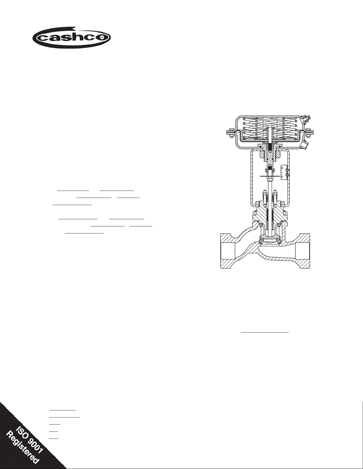
The Model 964 is a pneumatically actuated, sliding
stem globe-style control valve. Sizes are 1/2",3/4",
1", 1-1/2", & 2". Available in Cast Iron and Cast Steel
body ma te ri als.
Failure position is determined by actuator for:
"D" = Direct action; on increasing air loading pressure,
the actuator stem extends. Fail-safe position is with
the stem retracted.
"R" = Reverse action; on increasing air loading pres-
sure, the actuator stem retracts. Fail-safe position is
with the stem extended.
IOM-964
12-13
The valve is designed primarily for general service
or utility applications such as steam, air, oil, gas and
water.
SECTION II
II. REFERENCES
Refer to Technical Bulletin 964-TB for complete
tech ni cal specifi cations of a Model 964 coupled with
either Cashco Actuator Model C27 or C53.
www.cashco.com/techbulletins/964.pdf
Refer to following Installation, Operation & Main te nance Manuals (IOM’s) for either actuator and/or
devices that maybe mounted to a Model 964:
Actuators: www.cashco.com/IOM/C27-C53.pdf
Positioners:
P/P: www.cashco.com/techbulletins/9540l.pdf
I/P: www.cashco.com/techbulletins/srd991.pdf
I/P: www.cashco.com/iom/PS2iom.pdf
Model 964
with ATO - FC Actuator
ABBREVIATIONS
ATC–FO – Air–to–Close, Fail Open
ATO–FC – Air–to–Open, Fail Close
CCW – Counter Clockwise
CW – Clockwise
D or DIR – Direct Acting
IAS – Instrument Air Supply
LOAD – Positioner Output Air Pressure
R or REV – Reverse Acting
SIG – Output Signal from Instrument
V – Vent
Page 2
SECTION III
CAUTION
For welded installations, all internal trim parts and
seals, must be removed from body prior to welding
into pipeline. The heat of fusion welding will dam age
non-metallic parts if not re moved. NOTE: This does
not apply to units equipped with extended pipe nip ples.
III. INSTALLATION
A. Orientation:
1. Recommended ori en ta tion when in stalled in
a hor i zon tal pipeline with the stem ver ti cal.
Valves may also be in stalled in ver ti cal pipe lines with stems hor i zon tal.
3. If pipe reducers are located before and/or after
the valve body, keep the reducers as close as
prac ti cal to the valve body; this is especially
important where the reducers are more than
one line size larger than the valve body size,
which is common in gaseous ser vice.
4. Clean the piping of all foreign debris, in clud ing
chips, weld scale, weld spatter, oil, grease,
sand or dirt prior to in stall ing the control valve.
This is an absolute re quire ment for valves
supplied with composition soft seats. System
start-up strain ers, for removal shortly after
initial start-up, are rec om mend ed.
5. Field hydrostatic testing the com plet ed piping
system to 1-1/2 x CWP in psig indicated on the
nameplate, including the 964, is ac cept able.
If hydro test pressure exceeds the 1-1/2 x
CWP limit, the 964 must be re moved for such
testing. Before pres sur iza tion, the valve plug
should be lifted from the seat if of ATO-FC
action. Tighten packing as re quired.
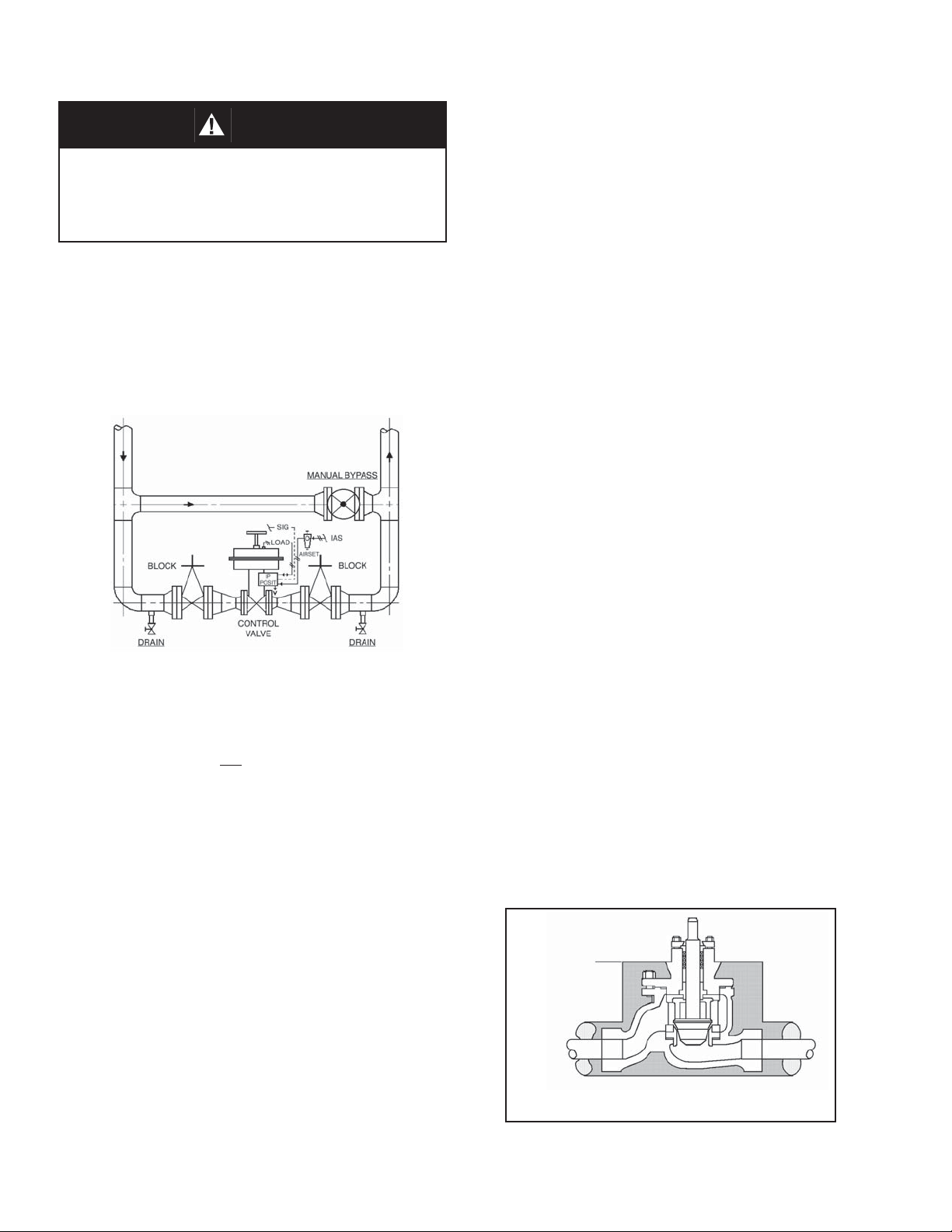
Figure 1: Typical Control Valve Station
2. Outdoors, all in stal la tions may be ori ent ed any
angle from hor i zon tal-to-vertical.
3. Valves are not recommended for in stal la tion
with the actuator oriented down wards..
B. Piping System:
1. It is recommended that the control valve unit
be in stalled with a double-block and bypass
as in di cat ed in Figure 1. This ar range ment is
rec om mend ed es pe cial ly where main te nance
will be done on the valve body while still installed in the pipeline.
2. Pipe unions are recommended for NPT
screwed or socket welded installations to al low
complete removal from sys tem. If re mov al
for main te nance is by cutting torch for socket
welded valves, leave suffi cient pipe nipple
space be tween the 964 body and the next
piping com po nent up or down stream to allow
socket weld couplings for re-in stal la tion.
6. In placing thread sealant on pipe ends prior
to en gage ment, ensure that excess ma te ri al
is removed and not allowed to enter the valve
upon start-up.
7. Flow Direction: Install so the fl ow direction
match es the arrow marked on the valve body.
8. For best performance, install in well drained
hor i zon tal pipe, properly trapped if a steam
service ap pli ca
tion.
9. Valves are not to be direct buried un der ground.
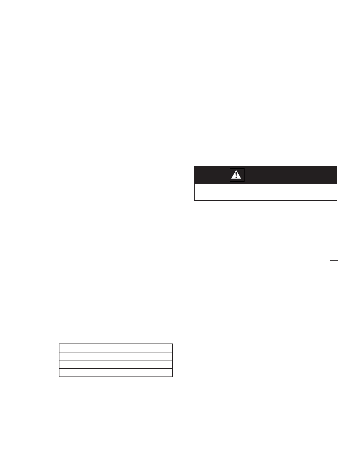
10. Insulation may be applied as in di cat ed in Figure 2. Drain age away from the packing area
must be ensured when fully in stalled, sealed
and lagged for outdoors in stal la tion.
Limit of
Bonnet
Insulation
Figure 2: Body Insulation
IOM-9642
Page 3
11. Undue piping stress/strain or bend ing
torques may not be trans mit ted thru the
valve body. One pipe (inlet or outlet) should
be an chored rig id ly for pip ing that is “hot” or
“cold” with respect to ambient tem per a ture;
the re main ing pipe (in let or out let) should
be sup port ed and guid ed to ensure uni di rec tion al ex pan sion/con trac tion.
C. Air Supply:
1. Use a desiccant dried, instrument quality
air supply. Such a supply is recommended
for outdoor installations, and is required in
areas of freezing weather conditions.
IV. START-UP
A. General:
1. Ensure that the Model 964 unit has been
prop er ly adjusted and cal i brat ed, in clud ing
the po si tion er, if in stalled.
2. Recommend startup to be in a “man u al”
mode. This pro ce dure assumes dou ble
block (iso la tion) and bypass valves for the
“control valve station”. See Fig ure 1.
3. Start with either of the two block valves
closed, with the other open. The bypass
valve should be closed. Pres sur ize sys tem,
if pos si ble/prac ti cal.
4. Back out the airset’s adjusting screw until
loose.
2. If air supply contains moisture and /or lubricating oil, the air should be fi ltered with
a coalescing type of fi lter prior to use in
stroking the actuator.
3. Failure to remove moisture will cause corrosion to the internals of the actuator casings.
4. Connections for the air supply are 1/4" female
NPT. Use a suitable pipe thread sealant
when installing the pipe or tube fi tting. DO
NOT allow sealant to enter the tube/pipe.
SECTION IV
CAUTION
DO NOT WALK AWAY AND LEAVE A MANUALLY CONTROLLED CONTROL VALVE UNATTENDED!
8. Confi rm that action of con trol ler and po si-
tion er - direct or reverse - are producing
the de sired re sponse in the con trol unit.
Con fi rm that the con trol valve “fail” po si tion
is as re quired.
9. Hereafter, the procedure as sumes that ac tu al
fl uid fl ow may be established. This may not
be practical / pos si ble in all cas es; if so, vary
procedure as re quired.
Always “heat” or “cool” down the system
pip ing SLOW LY by open ing the control valve
sta tion by pass valve in small in cre ments.
IOM-964
5. Turn on air supply pressure.
6. Adjust the air supply airset (fi l ter-reg u la tor)
to the proper lev el as in di cat ed as follows:
Bench Setting Airset Output
psig (Barg) psig (Barg)
5–15 (.34–1.0) 20 (1.4)
15–60 (1.0–4.1) 75 (5.2)
7. Place loop controller into “man u al” mode.
Vary setting from minimum - mid-range max i mum SIG output. Ob serve re sponse of
con trol valve unit to these chang es of input
SIG. The valve should fully stroke at the
vari a tion from min i mum SIG to max i mum
SIG; the mid-range SIG should have the
valve stem travel at/near 1/2 open.
10. With one of the control valve station block
valves still closed, and the loop con trol ler
still in “man u al” mode, open by pass valve
and vary fl ow rate man u al ly to ob serve the
re sponse of the con trol ler and control valve
unit to geth er.
11. Attempt to develop manual con trol of the
loop by opening/clos ing the man u al by pass
as re quired, or by manually con trol ling main stream fl ow as re quired.
12. When the control valve is partially open, crack
open slowly the closed block valve while
si mul ta neous ly clos ing the by pass valve.
Con tin ue this pro ce dure until the bypass is
closed and the block valves are both fully
open. The system is still under “man u
al”
3
Page 4

mode control, but all fl ow is pass ing through
the control valve.
13. Vary controller “manual” SIG output until
match ing the “au to mat ic” SIG output, then
V. MAINTENANCE
change the mode of the controller over to
“automatic”, and the loop will ex pe ri ence a
min i mum of upset con di tions, and will be in
au to mat ic control.
SECTION V
WARNING
SYSTEM UNDER PRES SURE. Prior to per form ing any
maintenance, isolate the valve/actuator from the sys tem
and relieve all pressure. Fail ure to do so could result in
personal injury.
A. General:
1. Maintenance procedures here in af ter are
based upon re mov al of the valve/ac tu a tor
unit from the pipe line where in stalled.
2. Owner should refer to Owner’s pro ce dures for
re mov al, handling and cleaning of non-re us able parts, i.e. gaskets, suitable sol vents, etc.
3. Valves supplied from the factory use a
gasket sealant, Federal Process Company,
PLS2, or equal. Owner may use such aids
provided the aids are com pat i ble with the
Owner’s fl uid.
4. All indicated Item Numbers that are with
re spect to the actuator assembly (AA) are
in pa ren the sis and un der scored; i.e (20).
All Item Num bers that are with respect to
the body assembly (BA) of a Model 964
are not un der scored; i.e. (32). Reference
with respect to the po si tion er is in double
parentheses; i.e. ((AP)).
5. Special care must be exhibited when
ro tat ing the stem (3) of the valve to
not mar that portion of the surface of
the stem (3) where it contacts with the
pack ing (6). To rotate the stem (3), use
the jam nuts (18) or grasp stem with softjawed pliers. NOTE: When using the jam
nuts (18) to rotate the stem (3), use the
upper jam nut to rotate the stem CW, and
the lower jam nut to rotate the stem CCW,
when viewed from above valve stem.
6. Hereafter, whenever text has the fol low ing
no ta tion, “(Note PA.)”, the fol low ing text is
to be ap plied;
“For ATO-FC reverse action units,
connect a temporary air source to the
actuator and pres sur ize to a level suf fi cient to initiate travel to ap prox i mate ly
mid-stroke.
7. Hereafter, whenever text has the fol low ing
no ta tion, “(Note RP.)”, the fol low ing text is
to be applied:
“For ATO-FC reverse action units, re lease all tem po rary air pressure.
B. Actuator Removal:
1. Secure the body (1) in a vise with the actuator as sem bly (AA) oriented ver ti cal ly. Place
matchmarks between the body (1) bon net
fl ange, the bonnet (2) fl ange, and the yoke
(3) to assist in fi nal ori en ta tion when the
body is dis as sem bled and/or the ac tu a tor
removed. If actuator has handwheel - see
Actuator IOM for removal instructions.
2. (Note PA.) Using blunt end tool, ham mer
rap the tool to loosen yoke nut (29) turning
CCW (viewed from above) ap prox i mate ly 2
rev o lu tions. Secure the ac tu a tor stem (6).
Loos en the stem jam nuts (18) by rotating
CW (viewed from above) one-at-a-time to
base of stem (3) threads.
3. Fully loosen any accessory de vic es that
are con nect ed to the stem (6) or (3) such
as ac ces so ry plate ((AP)) for po si tion
4. Loosen packing (6) by rotating nuts (15)
CCW 2-3 rev o lu tions. (Note RP.).
er.
IOM-9644
Page 5

NOTE: To fully disengage the actuator stem (6)
from the plug/stem (3) is a two-step pro ce dure.
Be aware of the valve’s stroke length as in di cat ed
on the name plate (40) before be gin ning dis en gage ment. During the dis en gage ment, mea sure
the dis tance ex tend ed, and stay at least 1/8" (3
mm) away from the full stroke length. Count and
record the number of rev o lu tions for each step in
the box below:
For Steps 5 and 6: Count the number of revolutions
to disengage plug/stem from actuator stem:
Step A. Step B.
TOTAL:
5. For ATO-FC Reverse Action Units:
a. (Note PA.)
b. Step A. Rotate plug/stem (3) CW (viewed
from above) to disengage the ac tu a tor
stem (6) from the plug/stem (3), while
holding the actuator stem (6). Record
the num ber of plug/stem rev o lu tions for
Step A above. When the dis en gage ment
reach es about 50% of full stroke trav el
Step A is com plet ed. (Note RP).
c. Step B. Support the actuator as sem-
bly (AA) from above. Fully loosen
yoke nut (29). Lift the actuator as sem bly (AA) up wards ap prox i mate ly
1/4"-3/8" (6-8 mm). Again, rotate plug/
stem (3) CW (viewed from above) to
dis en gage the ac tu a tor stem (6) from the
plug/stem (3) while holding the ac tu a tor
stem (6). Record the number of plug/
stem (3) rev o lu tions for Step B above.
This should allow the stems (6) (3) to
fully dis en gage.
NOTE: Take notice of the parts “dan gling
loosely” about the plug/stem (3), the order
of their lo ca tion and their proper orientation.
d. Fully raise the actuator assembly (AA)
from the valve body assembly (BA).
Re move cautiously to prevent dan gling
parts - position indicating washer (26),
ac ces so ry plate ((AP)), yoke nut (29) from fall ing.
6. For ATC-FO Direct Action Units:
a. Step A. Rotate plug/stem (3) CW (viewed
from above) to disengage the ac tu a tor
stem (6). Do not rotate the plug (3)
into the seat (11). Record the number
of plug/stem (3) rev o lu tions for Step
A above. When the dis en gage ment
reach es about 75% of full stroke travel,
Step A. is com plet ed.
b. Step B. Support the actuator as sem bly
(AA) from above. Fully loosen yoke nut
(29) and remove. Lift the actuator as sem bly (AA) upwards ap prox i mate ly 1/4" 3/8" (6-8 mm). Again, rotate plug/stem
(3) CW (viewed from above) to dis en gage the ac tu a tor stem (6) from the plug/
stem (3), while holding the actuator stem
(6). Record the number of plug/stem
rev o lu tions for Step B. This should allow the stems (6) (3) to fully disengage.
NOTE: Take notice of the parts “dangling
loosely” about the stem (3), the order of their
lo ca tion and their proper orientation.
c. Fully raise actuator assembly (AA) from
the valve body assembly (BA). Re move
cau tious ly to prevent dan gling parts – po si tion indicating washer (26), ac ces so ry
plate ((AP)), yoke nut (29) - from falling.
C. Actuator Replacement:
1. Secure body assembly (BA) in a vise with
the plug/stem (3) oriented ver ti cal ly. Push
plug/stem (3) down until the plug touches
the seating surface in the body.
2. Secure the actuator assembly (AA) from
above. Use matchmarks from B.1. previous
to assist with (BA) and (AA) alignment.
3. This procedure assumes that the bonnet (2)
has been bolted to the body (1), with stem
jam nuts (18) threaded on the plug/stem (3).
4. Lower actuator assembly (AA) until the plug/
stem (3) penetrates the opening in the yoke
(3). Re po si tion the “dangling parts” - yoke
nut (29), ac ces so ry plate ((AP)) or in di cat ing washer (26) - over threaded end of plug/
stem (3). Con tin ue to lower the actuator
assembly (AA) until there is ap prox i mate ly
1/4" (6 mm) space between the two stems
(6) (3).
IOM-964
5
Page 6

5. For ATC-FO: Connect a temporary air supply
hose that has an ad just able airset with gauge
to the ac tu a tor inlet to allow pres sur iza tion.
Slowly pressurize actuator to bring the ac tu a tor
stem (6) to with in 1/8" (3 mm) of reaching the
plug/stem (3).
6. With hand lift plug/stem (3) up to touch ac tu a tor
stem (6). Rotate plug/stem (3) CCW (viewed
from above) to en gage with ac tu a tor stem (6).
Use the total number of revs en gage ment
recorded in Step V.B. as the guide to control
engagement of the stems (6) (3). While en gag ing, rotate yoke nut (29) as able to help
stabilize top works, continue to pres sur ize the
ac tu a tor in 2-3 psi (.15-.20 Bar) in cre ments
in an al ter nat ing se quence with the distance
en gaged until the total num ber of revs engaged
is reached.
jam nuts (18) by rotating CCW (viewed from
plug end) while se cur ing the actuator stem
(6) with soft-jawed pliers.
8. Loosen stem packing (6) by turn ing nuts (15)
CCW to a point just short of dis en gage ment
from the threads.
9. While securing the actuator stem (6) by softjawed pliers, rotate the valve stem as sem bly
(3) CCW (viewed from plug end). Record the
number of rev o lu tions of dis en gage ment in
the box below:
Number of revolutions to disengage plug/stem as-
sembly from actuator stem.
10. Remove packing fl ange nuts (15) with CCW
ro ta tion.
7. Hand-tighten yoke nut (29) until fully po si tioned
with the yoke (3) sitting on the bonnet (2).
8. Secure “dangling parts” - ac ces so ry plate
((AP)) and indicating washer (26) - to ac tu a tor
stem (6) with stem jam nuts (18).
9. Ham mer rap yoke nut (29) until tight. (Release
tem po rary air source.)
D. Trim Removal and Re place ment:
1. Secure body (1) assembly (BA) in a vise with
actuator assembly (AA) di rect ed up wards.
Place match marks be tween the body (1) and
the bonnet (2).
2. Secure the actuator assembly (AA) with an
over head support capable of ver ti cal lift.
3. (Note PA.) Loosen all bonnet stud nuts (17)
(four nuts for 1/2" thru 1-1/2" sizes; six nuts
for 2" size).
4. Ensure actuator support is “taut”; i.e. hold ing
weight of actuator.
11. Partially withdraw plug/stem as sem bly (3).
Re move position in di ca ting washer (26), both
jam nuts (18), packing fl ange (4), pack ing
follower (5), and ac ces so ry plate ((AP)), if
installed.
12. Fully withdraw stem/plug as sem bly (3). For
1/2" thru 1-1/2" sizes, cage (10) may have
come loose see Step 6 above.
13. Using a sharp, hooked-end, pick-type tool,
hook and pull the packing rings (6) up and out
of the bonnet’s (2) packing bore individually.
Discard old packing (6).
CAUTION
Take extreme care to not mar internal wall surface of the
bonnet (2).
14. Using a sharp pointed tool, remove packing
washer (23) and packing spring (24).
15. Solvent clean all loose parts with suitable
solvent and let dry.
5. Remove all bonnet bolting nuts (17).
6. Lift the actuator assembly (AA), to geth er with
bon net (2) and stem as sem bly (3) vertically
out of the valve body (1). Lay the topworks
assembly down onto a work bench horizontally.
For 1/2" - 1-1/2" sizes, re move the cage (10)
and seat ring (11) from the body (1) cavity.
7. From the top works as sem bly, loosen the stem
16. For SIZES 1/2” thru 1-1/2", inspect guide
bushing (8) in-place, as the bushing (8) is
press fi t into the bonnet (2). If worn badly
or “scored”:
a. Remove bonnet (2) by removing yoke
nut (29).
b. Hydraulically press guide bushing (8)
“out” of bonnet (2); press “in” new
guide bushing (8).
c. Reinstall bonnet (2) back thru yoke (3),
and secure with yoke nut (29).
IOM-9646
Page 7

17. For SIZE 2", inspect guide bush ing (8) in-
place, as the bush ing (8) is press fi t into the
bonnet (2). If worn or “scored:
a. Remove bonnet (2) by re mov ing yoke nut
(29).
b. Remove retaining ring (9).
c. Hydraulically press guide bush ing (8)
“out”; press “in” new guide bushing (8)
into bon net (2).
d. Replace retaining ring (9).
e. Reinstall bonnet (2) back to geth er with ac-
tu a tor yoke (3), securing with yoke nut (29).
18. Examine cage (10), seat ring (11), plug/stem
(3) seat insert (27), seat retainer (28) and
gasket (13) for wear. Re place all worn parts.
Refer to Figure 3 for correct orientation of
composition seat parts.
19. Examine stem (3) in critical fi nish zone where
contact is made with the packing (6). It is desirable to restore the surface of the stem (3)
to a #8 Ra μ-in surface fi nish; metal removal
should not exceed 0.001-inch material. A
deeply scratched or pitted stem (3) should
be replaced.
25. For SIZES 1/2" - 1-1/2", lower packing spring
(24) into bonnet (2) pack ing bore.
For SIZE 2", fi rst slide packing stop (7) into
bonnet (2) packing bore followed by the packing spring (24).
26. Lower packing washer (23) into bonnet (2)
packing bore. Ensure that wash er (23) is
rest ing fl at on the packing spring (24).
27. Carefully place lower adapter (6.3) of packing ring set (6) over stem’s (3) threaded end,
properly oriented. Using the packing follower
(5), push the lower adapter into the bonnet’s
(2) packing bore.
20. Plug head of stem (3) assembly for metal
seated design may be hand lapped using
suitable lapping com pound. If hand lap ping
will not restore surface fi nish to an ac cept able
de gree, re place ment of stem (3) as sem bly
and seat ring (11) is rec om mend ed.
21. Examine the inner surface of the bonnet’s
(2) packing bore. It is desirable to restore
the surface of stuffi ng box to a #16 Ra μ-in
surface fi nish; metal removal should not ex-
ceed 0.001-inch material. If inner surface is
deeply scratched or pitted, bonnet (2) should
be replaced.
22. Examine packing follower (5) for corrosion.
Replace if signifi cantly corroded. Remove
follower bushing (25) from inside of packing
follower (5) and replace with new.
23. Remove gasket (12) (13), clean gas ket fac ing
sur fac es and replace with new gas ket (12) (13).
24. Place seat ring (11) [and cage (10) - for sizes
1/2" - 1-1/2"] into the body (1) cavity. Insert
the threaded end of stem (3) thru bonnet (2)
until it ap pears thru the top side. Place bonnet on body. (NOTE: The cage for 2" size
is integral with bonnet (2).)
Packing Orientation
28. Carefully place a packing ring (6.2) properly
oriented over the stem’s (3) end and push
into the packing bore similar to the adapter
(6.3). Repeat process for balance of rings.
29. Carefully place upper adapter (6.1) over
threaded end of stem (3).
30. Slide packing follower (5) with new follower
bushing (25) over threaded end of stem.
31. Place packing fl ange (4) over end of stem
(3) and over packing studs (14). Install both
jam nuts (18) on stem and rotate to bottom
of stem threads.
32. Slide indicating washer(26) and accessory
plate ((AP)), if installed, over threaded end
of stem (3).
33. Engage plug/stem (3) into ac tu a tor stem
(6) per the same number of rev o lu tions
recorded per D. Step 9.
34. Rotate both jam nuts (18) up tight against
position in di ca ting washer (26).
IOM-964
7
Page 8

35. Tighten packing nuts (15) evenly in ½ revolution increments, until the packing fl ange (4)
is resting evenly on the upper edge of the
bonnet (2) at the packing box. Snug both
nuts (15) tightly.
36. Raise actuator assembly (AA). (Note RP.)
Lower into body (1) over bonnet studs/bolts
(16). Align with match marks.
37. For ATO-FC action units, wiggle the ac tu a tor
as sem bly (AA) to assist in align ment.
38. For ATC-FO action units, pres sur ize ac tu a tor
to the “high er” number of the bench set range
in di cat ed on nameplate (12) plus 2 psig (.14
Barg); for 5-15 psig (.34-1.03 Barg) bench
setting, pres sur ize to 17 psig (1.17 Barg).
VI. CALIBRATION
This should “lift” the bonnet (2) and “seat”
the plug (3) fi rmly into the seat ring (11) for
align ment pur pos es. Wiggle the ac tu a tor
as sem bly (AA) to assist in align ment.
39. Wrench-tighten the bonnet bolt ing (16) (17) in
an al ter nat ing cross-pat tern in 1/4 rev o lu tion
in cre ments. Torque bonnet bolt ing to 30-35
ft/lbs (40-47 N-M) for sizes 1/2" - 1-1/2" , and
50-55 ft/lbs (66-73 N-M) for size 2"
40. For ATC-FO action units, release ac tu a tor
pres sure.
41. Hammer rap yoke nut (29) tight.
42. Calibrate unit per Section VI.
SECTION VI
A. General:
1. This section only covers cal i bra tion of the
control valve with Actuator Models C27/C53.
2. Positioner, if in stalled, requires ref er ence to
the spe cifi c positioner mod el IOM for prop er
cal i bra tion pro ce dure.
3. All indicated items numbers that are with re spect to IOM-C27-C53 will be in pa ren the sis
and un der scored; i.e. (20); those that reference
the po si tion er IOM will be in double paranthesis; i.e. ((AP)). All item numbers that are with
respect to this IOM-964 are not un der scored;
i.e. (3).
B. Procedure - Reverse Action, ATO-FC:
1. Reference the name plate (40) at tached to
the ac tu a tor yoke (3). De ter mine the bench
set ting of the in stalled range springs (10) from
the name plate (40); i.e. 5-15 psig (.34 -1.0
Barg), or 15-60 psig (1-4.1 Barg).
2. Connect a temporary air supply with an in-line
ad just able airset regulator and gauge to the
lower actuator con nec tion. See Section IV. A.
6. for appropriate supply pressure. DO NOT
LOAD with any air pressure at this point.
3. To determine when stem/plug (3) begins to
lift out of the seat, touch the stem above the
packing studs with one fi nger. (Stem will begin
to move when actuator pressure exceeds
the spring load.)
4. Slowly pressurize the ac tu a tor to a pres sure
equal to the lower pres sure lev el of the bench
setting; i.e. for a 5-15 psig (.34 -1.0 Barg)
range, set pressure at 5 psig (.34 Barg). Take
note of pressure reading when the stem fi rst
begins to move.
5. If the loading pressure for the start of stem
movement is below the lower end of the
desired bench setting, then the com bined
stem (3, 6) length is too short.
a. Rotate both jam nuts (18) down to base of
threads on stem (3) and tighten together.
b. Increase pressure in the actuator to
approximately mid range of the bench
setting.
c. Rotate upper jam nut CW to increase
the combined stem length. DO NOT
allow actuator stem (6) to rotate in the
actuator.
d. Rotate upper jam nut CCW to hold indi-
cating washer (26) up against stem (6).
e. Release all pressure from the actuator
and repeat Step 4 previous.
6. If the loading pressure for the start of stem
movement is above the lower end of the
desired bench setting, then the com bined
stem (3, 6) length is too long.
a. Rotate both jam nuts (18) down to base of
threads on stem (3) and tighten together.
IOM-9648
Page 9

b. Increase pressure in the actuator to ap-
proximately mid range of the bench setting.
c. Rotate lower jam nut CCW to shorten the
combined stem length. DO NOT allow
actuator stem (6) to rotate in the actuator.
d. Rotate upper jam nut CCW to hold indicat-
ing washer (26) up against stem (6).
e. Release all pressure from the actuator
and repeat Step 4 previous.
7. After the opening set point pressure has been
established, rotate lower jam nut (18) CCW
up tight under the upper jam nut.
8. Release all pressure from the actuator.
6. for appropriate supply pressure. DO NOT
LOAD with any air pressure at this point.
3. To determine when stem/plug (3) makes
contact with the seat and travel stops, touch
the stem above the packing studs with one
fi nger. (Stem movement will stop when the
plug engages the seat.)
4. Slowly pressurize the ac tu a tor to a pres sure
equal to the upper pres sure lev el of the bench
setting; i.e. for a 5-15 psig (.34 -1.0 Barg)
range, set pressure at 15 psig (1.0 Barg).
Take note of the pressure reading when stem
travel actually stops.
9. Examine the location of the in di ca ting washer
(26) to the "C" mark on the in di ca tor plate
(23), mak ing sure to use the “top edge” of the
in di ca ting washer (26) as the ref er ence point.
Adjust indicator plate as needed.
10. Increase pressure in the actuator until the
indicating washer (26) is in alignment with the
"O" mark on the indicator plate.
11. To limit the up travel at the desired stroke
length, rotate the travel stop nut (52) CW and
secure to bottom of the attachment hub (4).
NOTE: Secure the actuator stem (6) by the
fl ats when rotating the travel stop nut.
NOTE: “Stroke” length is in di cat ed on the
name plate (40), and is the dis tance be tween
the “C” and “O” marks of the indicator plate
(23).
NOTE: The proper calibration of the ac tu a tor/
valve unit will occur when at the lower pressure
level of bench setting, the valve plug (3) will
just begin to travel from the "C" po si tion. At the
upper level of the bench setting, the actuator
pressure should be within ± 8% of the upper
bench setting for the designed stroke length.
12. Release all pres sure from actuator.
C. Procedure - Direct Action, ATC-FO:
1. Reference the name plate (40) at tached to
the ac tu a tor yoke (3). De ter mine the bench
set ting of the in stalled range springs (10) from
the name plate (40); i.e. 5-15 psig (.34 -1.0
Barg), or 15-60 psig (1-4.1 Barg).
5. If the loading pressure, when the stem movement stops, is below the upper end of the
desired bench setting, then the com bined
stem (3, 6) length is too long.
a. Rotate both jam nuts (18) down to base of
threads on stem (3) and tighten together.
b. Decrease pressure in the actuator to
approximately mid range of the bench
setting.
c. Rotate lower jam nut CCW to shorten the
combined stem length. DO NOT allow
actuator stem (6) to rotate in the actuator.
d. Rotate upper jam nut CW to hold indicat-
ing washer (26) up against stem (6).
e. Release all pressure from the actuator
and repeat Step 4 previous.
6. If the loading pressure when the stem move-
ment stops is above the upper end of the
desired bench setting, then the com bined
stem (3, 6) length is too short.
a. Rotate both jam nuts (18) down to base of
threads on stem (3) and tighten together.
b. Decrease pressure in the actuator to
approximately mid range of the bench
setting.
c. Rotate upper jam nut CW to increase the
combined stem length. DO NOT allow
actuator stem (6) to rotate in the actuator.
d. Rotate upper jam nut CCW to hold indicat-
ing washer (26) up against stem (6).
e. Release all pressure from the actuator
and repeat Step 4 previous.
7. After the closed set point pressure has been
established, rotate lower jam nut (18) CCW
up tight under the upper jam nut.
2. Connect a temporary air supply with an in-line
ad just able airset regulator and gauge to the
upper actuator con nec tion. See Section IV. A.
IOM-964
8. Increase pressure in the actuator to the upper
pressure level of the bench setting.
9
Page 10

9. Observe the location of the in di ca ting washer
(26) to the "C" mark on the in di ca tor plate
(23), mak ing sure to use the “top edge” of
the in di ca ting washer (26) as the ref er ence
point. Adjust indicator plate as needed.
10. Slowly release air pressure in the actuator
until the indicating washer (26) is in alignment
with the "O" mark on the indicator plate.
11. To limit the up travel at the desired stroke
length, rotate travel stop nut (52) CW and
secure to bottom of the attachment hub (4).
NOTE: Secure the actuator stem (6) by the
fl ats when rotating the travel stop nut.
NOTE: “Stroke” length is in di cat ed on the
name plate (40), and is the dis tance be tween
the “C” and “O” marks of the indicator plate
(23).
NOTE: The proper calibration of the ac tu a tor/
valve unit will occur when at the upper pressure level of bench setting, the valve plug (3)
will be in the "C" po si tion. At the lower level
of bench set the actuator pressure should
be within ± 8% of the lower bench setting
for the designed stroke length.
12. Release all pres sure from actuator.
IOM-96410
Page 11

SECTION VII
VII. TROUBLE - SHOOTING GUIDE
1. Valve is “jumpy” in stroking.
Possible Causes Remedies
A. Excess packing friction. A1.
B. Installed backwards. B. Install per fl ow arrow.
2. Valve makes “screeching” noise.
Possible Causes Remedies
A. Excess pressure drop. A. Bring pressure drop within design limits.
B. Guide bushing wear. B. Re place guide bushing.
C. Misalignment. C. Realign body-stem-actuator.
3. Valve exhibits “excess” vibration.
Possible Causes Remedies
A. Excess pressure drop. A. Bring pres sure drop within design limits.
B. Guide bushing wear. B. Re place guide bushing.
C. Excessive cavitation in liquid service. C1.
D. High outlet velocity. D1.
Realign body - stem - actuator.
A2.
Packing follower too tight for optional packing designs.
A3.
Install positioner.
A4.
Increase bench set by changing to stiffer actuator
range spring. Will require positioner if not installed.
May require different airset.
Change operation parameters to relieve causes of
C2.
cavitation.
Replace valve with valve equipped for cavi ta tional control.
Re duce fl ow rate and/or pressure drop.
D2.
Use multiple valves in series or parallel.
D3.
Increase outlet pipe size.
4. Valve exhibits “excess” seat leakage.
Possible Causes Remedies
A. Excess pressure drop. A. Re duce pres sure drop conditions.
B. Improper actuator bench setting. B1.
C. Metal seat design instead of composition seat
design.
D. Excess wear. D1.
E. Misalignment. E. Realign body - stem - actuator.
F. Composition seat failure. F1.
G. Seat ring gasket failure. G. Replace seat ring gasket.
IOM-964
Cali brate actuator-to-valve.
B2.
Assure proper engagement of actuator stem-to-valve
stem. Adjust as calibration dictates.
C. Convert valve to composition seat design.
Oversized valve op er at ing too close to seat; go to re-
D2.
duced trim.
D3.
Incorporate stellite trim.
D4.
Remove particulate.
Possible excess cavitation in liquid service. Change
D5.
operation parameters.
Re-lap plug-seat surface.
Replace soft seat.
F2.
Remove "dirty" portion of fl uid causing failure.
11
Page 12

5. Premature packing leakage.
Possible Causes Remedies
A.
Over-temperature. A1.
Bring process temperature to 450°F (232°C) or less.
A2.
Remove in su la tion along bonnet; al low di rect con tact
with ambient air.
B.
Misalignment. B. Realign body - stem - actuator.
C.
Wear. C1.
D.
Improper design for applied service. D1. Install alternate packing design.
Remove dirt/grit from fl uid.
C2.
Reduce cyclic travel.
6. Bonnet gasket leaking.
Possible Causes Remedies
A.
Improper bonnet bolting draw down.
A1.
Replace gasket and draw down bolting evenly in a
cross-pattern.
7. Body fl ange leakage.
Possible Causes Remedies
A.
Over-tightening fl ange bolting.
A1.
Loosen bolting, replace gasket, reinstall new fl ange
bolting.
A2.
Replace warped fl ang es.
B.
Improper pipe supports and anchors.
B.
Provide piping anchors and guides at control valve station. Restrain bending movements.
IOM-96412
Page 13

SECTION VIII
VIII. ORDERING INFORMATION
NEW REPLACEMENT UNIT vs PARTS "KIT" FOR FIELD REPAIR
To obtain a quotation or place an order, please retrieve the Serial Number and Product Code that was stamped
on the metal name plate and attached to the unit. This information can also be found on the Bill of Material
("BOM"), a parts list that was provided when unit was originally shipped. (Serial Number typically 6 digits).
Product Code typical format as follows: (last digit is alpha character that refl ects revision level for the product).
–
NEW REPLACEMENT UNIT:
Contact your local Cashco, Inc., Sales Rep re sen ta tive with the Serial Number and Product code.
With this information they can provide a quotation
for a new unit including a complete description,
price and availability.
CAUTION
Do not attempt to alter the original construction of any
unit without assistance and approval from the factory. All
purposed changes will require a new name plate with appropriate ratings and new product code to accommodate
the recommended part(s) changes.
–
7
PARTS "KIT" for FIELD REPAIR:
Contact your local Cashco, Inc., Sales Rep re sen ta tive with the Serial Number and Product code.
Identify the parts and the quantity required to repair
the unit from the "BOM" sheet that was provided
when unit was originally shipped.
NOTE: Those part numbers that have a quantity indicated
under "Spare Parts" in column "A” refl ect minimum
parts required for inspection and rebuild, - "Soft
Goods Kit". Those in column “B” include minimum
trim replacement parts needed plus those "Soft
Goods" parts from column "A".
If the "BOM" is not available, refer to the crosssectional drawings included in this manual for part
identifi cation and selection.
A Local Sales Representative will provide quotation
for appropriate Kit Number, Price and Availability.
NOTES
The contents of this publication are presented for informational purposes only, and while every effort has been made to ensure their accuracy, they are not to be
construed as warranties or guarantees, express or implied, regarding the products or services described herein or their use or applicability. We reserve the right to
modify or improve the designs or specifi cations of such product at any time without notice.
Cashco, Inc. does not assume responsibility for the selection, use or maintenance of any product. Responsibility for proper selection, use and maintenance of any
Cashco, Inc. product remains solely with the purchaser.
IOM-964
13
Page 14

1/2"–1-1/2" Sizes MODEL 964
Figure 3: Composition Seat Ar range ment
IOM-96414
Page 15

2" Size MODEL 964
IOM-964
Item No. De scrip tion
1 Body
2 Bonnet
3 Plug & Stem Subassembly ‡
4 Packing Flange
5 Packing Follower
6 Packing ‡
7 Packing Stop (2" Size only)
8 Guide Bushing
9 Retaining Ring (2" Size only)
10 Cage
11 Seat Ring
12 Gasket - Body ‡
13 Gasket - Seat Ring ‡
Item No. De scrip tion
14 Packing Flange Stud
15 Packing Flange Nut
16 Studs - Body
17 Stud Nuts
18 Jam Nuts
23 Packing Washer
24 Packing Spring
25 Packing Follower (Bushing)
26 Indicating Washer
27 Seat Insert ‡
28 Seat Retainer
29 Yoke Nut
‡ Recommended replacement parts.
15
Page 16

Cashco, Inc.
P.O. Box 6
Ellsworth, KS 67439-0006
PH (785) 472-4461
Fax. # (785) 472-3539
www.cashco.com
email: sales@cashco.com
Printed in U.S.A. 964-IOM
Cashco GmbH
Handwerkerstrasse 15
15366 Hoppegarten, Germany
PH +49 3342 4243135
Fax. No. +49 3342 4243136
www.cashco.com
Email: germany@cashco.com
Cashco do Brasil, Ltda.
Al.Venus, 340
Indaiatuba - Sao Paulo, Brazil
PH +55 11 99677 7177
Fax. No.
www.cashco.com
Email: brazil@cashco.com
 Loading...