

Page 1
INSTALLATION, OPERATION & MAINTENANCE MANUAL (IOM)
MODEL 9540R
P/P - PNEUMATIC POSITIONER FOR ROTARY VALVES
I. DESCRIPTION AND SCOPE
Model 9540R is a single acting, compact, force-balance, pneumatic positioner used together with a
rotary motion adapter baseplate for 90° rotary control
valves. This positioner is utilized to characterize the
relationship between valve stem position and the
system’s control signal. This design is only suitable for
nominal 3-15 psig (.21-1.0 Barg) input signals, or split
range variations thereof.
IOM-9540R
06-03
SECTION I
Each unit comes complete with a set of built-in gauges
within the internals, and a visual stem position indicator; the cover includes a clear see-thru panel to
monitor gauges. Gauges monitor input “SIG” and
output “LOAD”.
The Model 9540R P/P positioner may be utilized as an
alternate to the standard Model 9000R rotary P/P
positioner, with the following current Cashco product
models:
Ranger QCT
Premier EZO
Premier (unlined)
PCV
5-13 psig
SIG
15-3 psig
PC
REV.
PROCESS
P2 = 100 psig
IAS
P1 = 500 psig
3-15 psig
DIR.
ATO-FC
P/P
LOAD
IAS
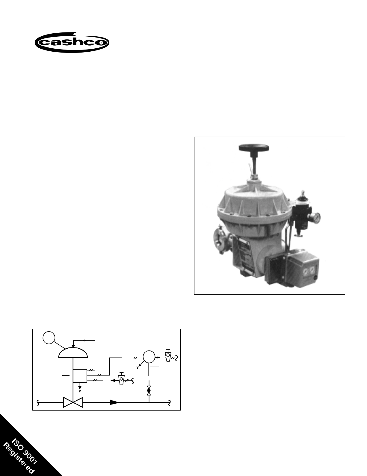
Figure 1: Typical Pressure Reducing Pneumatic
Control Loop – PCV with P/P Positioner
20 psig
Model 9540R Mounted on a
Cashco Ranger QCT Control Valve
IAS – Instrument Air Supply
PC – Pressure Controller
PCV – Pressure Control Valve
ATO-FC – Air-to-Open, Fail Close
ATC-FO – Air-to-Close, Fail Open
P/P – Pneumatic Input/Pneumatic Output
DIR – Direct Acting
REV– Reverse Acting
SIG – Controller Output Signal
V – Vent
CW – Clockwise Rotation
CCW – Counter-Clockwise Rotation
Page 2
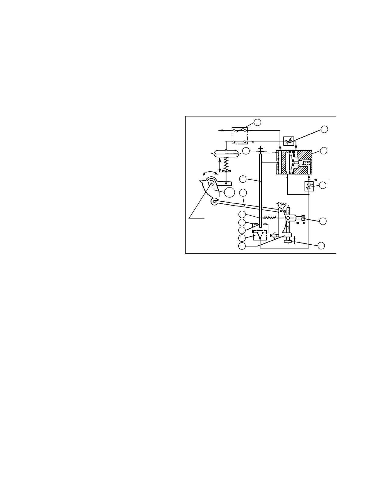
II. METHOD OF OPERATION (See Figure 2)
The positioner operates with the force balance
principle: the input signal “SIG” (3-15 psig) acts on the
input diaphragm (50). The stroke of the input
diaphragm is transferred to the flapper lever (38). The
resulting movement of the flapper varies the dynamic
pressure at the nozzle (51). This pressure acts on the
amplifier (53) and the change in output pressure
causes a movement of the valve’s rotary stem.
The rotary movement is back fed from the valve stem
(55), thru a characterization cam (24), to the feedback
lever (13) of the positioner, and transferred to the
stroke factor lever (19). The stroke factor lever (19) is
connected to the flapper lever (38) by means of a
range spring (41).
SECTION II
The normal factor set position of the bypass switch (3)
is “EIN” (ON) (pointer at 6 o’clock), and the positioner
will be operational. If the positioner bypass switch (3)
is set to the “AUS” (OFF) position (pointer at 9 o’clock),
the input signal “SIG” is supplied direct to the actuator;
i.e. the positioner is only practical for control valves
where the positioner action is “Direct” and the actuator
bench range is approximately equal to the 3-15 psig
“SIG”. Use of bench ranges with upper limits greater
than 15 psig will cause the control valve to not be able
to fully stroke when bypassed.
3
SIG
"LOAD"
Y
50
44
53
A force balance is created on the flapper lever (38)
when the force generated by the input diaphragm (50)
balances with the counter-force produced on the range
spring (41). This ensures that the valve stem position
is always characterized to the input signal.
Dynamic matching to the actuator (sensitivity, stability) is factory set by means of the throttle screw (42)
and the damping throttles (44). The stroke range and
zero are set by means of the stroke factor thumbscrew
(40) and the zero thumbscrew (39). The changeover
plate (15) is used to set either an increasing or
decreasing output pressure for an increasing input
signal, i.e. direct or reverse acting.
III. MOUNTING TO SPRING DIAPHRAGM
ACTUATORS
A. The following text applies to the field mounting of
a positioner to a valve originally not supplied with
a shaft-end positioner. See Appendix A to remove
9000R.
B. Mounting Kit:
1. A factory-supplied field mounting kit must
be obtained. Request “Model 9540R P/P
Field Installation Kit” (FIK) and indicate the
following:
Figure 2: Single-Acting Positioner Functional Diagram
SECTION III
Travel
38
24
13
Valve
Stem
41
51
52
N
15
19
U
e. Desired characteristic; i.e. =%, linear
f. ATO-FC or ATC-FO action.
2. An airset with gauge is required. Request
separately from positioner KIT.
3. If a positioner indicating switch (by Bettis or
Proximity Controls) is shaft-end-mounted, the
use of the position switch(es) must be abandoned or replaced with probe-type proximity
switch(es) (“Go” Series 70) mounted on the
yoke. NOTE:
These units are available on
1” – 4” Rangers and 3” – 4” Premiers only.
C. Mounting Side:
"IAS"
42
39
40
a. Unit’s serial number
b. Product model; i.e. Ranger, Premier, or
Premier EZO
c. Valve body size
d. Actuator bench range
When viewed from the valve stem end, with the
actuator casing defined as upwards (above stem),
the position indication portion should be to the
“left”, and the positioner section should be to the
“right’.
IOM-9540R2
Page 3

D. Existing Control Valve Modifications:
1. Refer to IOM-48 or IOM-148 for instructions
for the rotary actuators used on Ranger QCT,
Premier EZO and Premier (unlined).
d. Position the new positioner spacer (17)
over the valve stem (7 - Ranger, 3.2 Premier) end, oriented as shown below in
Figure 2.5.
2. All indicated Item Numbers that are with
respect to IOM-48 or IOM-148 will be in parenthesis and underscored; i.e. (
32). All part Item
Numbers that are with respect to this
IOM-9520R are not underscored; i.e. (32).
NOTE:
If no handwheel (58) or adjusting screw
assembly is provided with the actuator, it is
recommended that the rod end (9) be uncoupled from the arms (5) by removal of bolt
(40). See IOM-48 or IOM-148. Use of air
loading into the actuator casing (1) is possible, but introduces safety considerations;
i.e. use “tools” and not “fingers” inside the arm
housing (4) area.
3. Remove cover plate (20).
4. Steps to change the mounting and stem interconnection between the valve end-of-shaft
and the positioner unit. These changes bring
the positioner into compliance with NAMUR
Standard VDI/VDE #3845.
#48 Actuator: (See Figure 3)
a. Turn actuator handwheel CW to remove
stem windup torque. The linkage from the
actuator stem (9) will become slack. May
require 1-3 revolutions. This will ease
removal of cap screws (31).
b. Remove three cap screws (31), dial lens
(14), travel indicator dial (15), cover plate
(13), cap screw (32), travel indicator (16),
lock washer (55) and pin (51). Remove
bearing (18), both bearing flanges (19)
and indicator spacer (17).
c. Discard removed dial lens (14), travel
indicator dial (15), cap screw (32), travel
indicator (16), washer (55), pin (51) and
indicator spacer (17). Save only cover
plate (13), bearing (18) and both bearing
flanges (19) for re-use.
(Viewed looking
17
Actuator Casings
1, 2) on Topside
(
77
at Shaft end.)
Ranger
7
Premier
3.2
Figure 2.5: Spacer Orientation
e. Put Locktite #242 thread locking sealant,
or equal, onto the set screw (77). Engage
the set screw (77) into the tapped end of
the spacer (17), until the set screw (77) is
projecting out of the spacer (17)
3/16" – 1/4" (5 – 6 mm).
f. Position positioner baseplate (26) to
positioner mounting bracket (76) properly
oriented such that positioner baseplate
(26) bottom edge is parallel to the bottom
edge actuator arm housing (4). Opposite
side boltholes of bracket (76) must also
align with boltholes of actuator arm housing (4) and cover plate (13). Use four cap
screws (79) to secure the baseplate (26)
to the bracket (76). Place connected
parts (26, 76, 79) aside.
g. Position bearing flanges (19) with re-
tainer ball bearing (18) over the spacer
(17). Align the bearing flange (19) bolt
holes with the arm housing (4) bolt holes.
h. Position cover plate (13) over the bearing
flanges (19) aligning the cover plate (13)
bolt holes with those of the bearing
flanges (19). Hold cover plate (13) on
outer edge with fingers. NOTE:
Ensure
that the three tapped holes in the cover
plate (13) used to mount the bracket (76)
are near the 1 o'clock, 5 o'clock and 9
o'clock positions.
Engage three cap
screws (31) to secure spacer (17), bearing flanges (19) and cover plate (13)
securely to arm housing (4). NOTE
: It
may be necessary to rotate the actuator
manual handwheel operator (58) downwards, or alternately supply a small level
of air pressure (5-7 psig, .34 - .50 Barg) to
assist in aligning bolt holes for cap screws
(31). Do not tighten one cap screw (31)
until all three cap screws are partially
thread-engaged.
i. Position connected parts (26, 76, 79) of
Step 4f., above, with the bracket (76) up
and pressing against the cover plate (13),
engaging the tongue-and-groove joint
between the positioner baseplate rotary
shaft (32) and the spacer (17) with its
protruding set screw (77). Engage new
cap screws (78) to secure the bracket
(76) to the cover plate (13).
IOM-9540R
3
Page 4
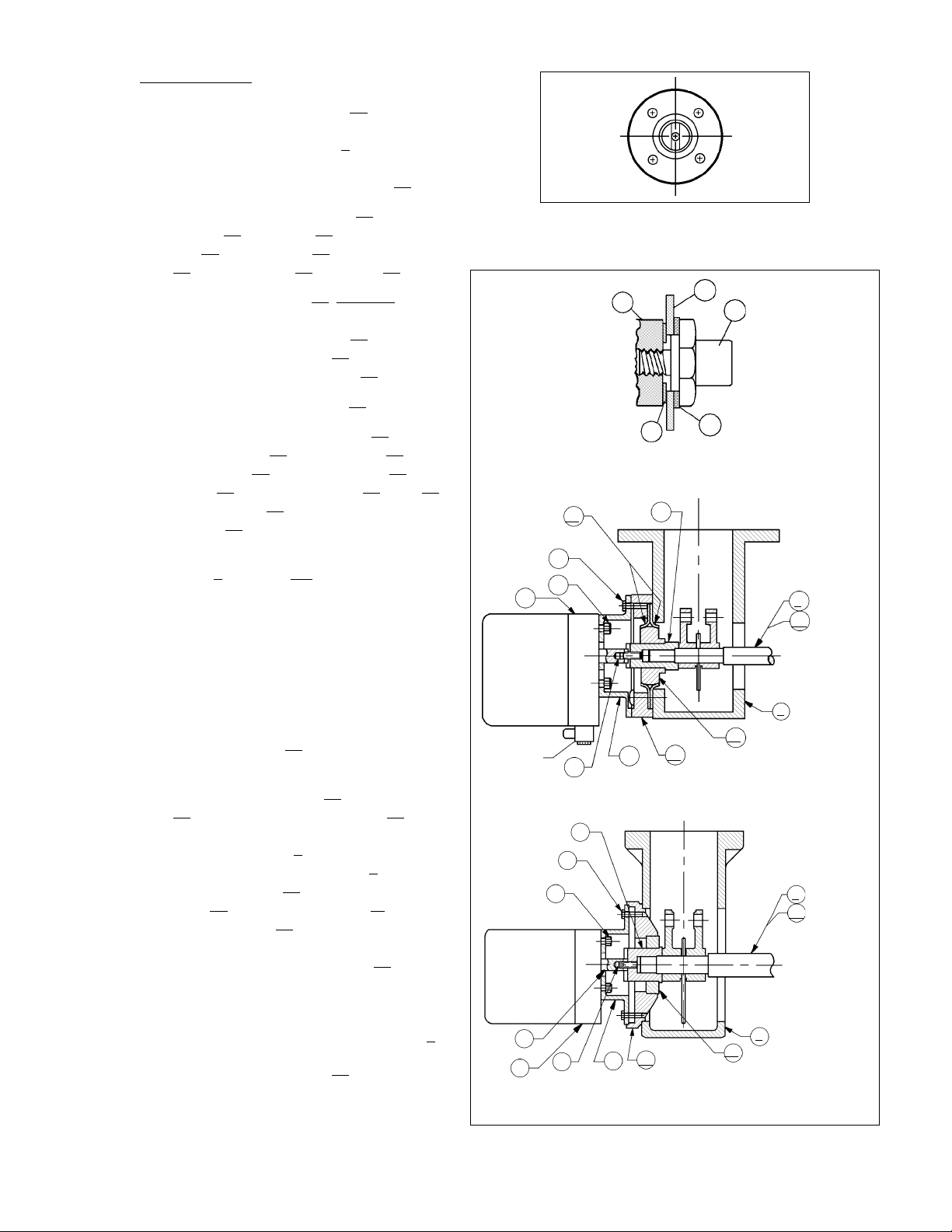
#148 Actuator: (See Figure 3)
a. Turn actuator handwheel (
58) CW to remove stem windup torque. The linkage
from the actuator stem (9) will become
slack. May require 1-3 revolutions. This
will ease removal of cover plate (13).
b. Remove four cap screws (34), two cap
screws (31), dial lens (14), travel indicator
dial (15), cap screw (32), travel indicator
(16), lock washer (55) and pin (51).
c. Remove cover plate (13) carefully, prying
out with a screwdriver or similar instrument. Shaft-end bearing (18) may slide
out when cover plate (13) is removed;
otherwise, remove bearing (18).
d. Remove indicator spacer (17).
e. Discard removed dial lens (14), travel
indicator dial (15), coverplate (13), two
cap screws (31), travel indicator (16), cap
screw (32), indicator spacer (17), pin (51)
and washer (55). Save only four cap
screws (34) for re-use.
f. Position the spacer (17) over the valve
stem (7 Ranger, 3.2 Premier) end, oriented as shown in Figure 2.5.
g. Put Locktite #242 thread locking sealant,
or equal, onto the setscrew ( 77). Engage
the setscrew (77) into the tapped end of
the spacer (17), until the setscrew (77) is
projecting out of the spacer (17) 3/16"–
1/4" (5–6 mm).
h. Position bearing (18) over the spacer (17)
and push fully inwards.
i. Position cover plate (13) over bearing
(18) ensuring that cover plate (13) gets
properly centered and shouldered within
the arm housing (4). Align the four bolt
holes within the arm housing (4). Engage
the cap screws (34) to secure the cover
plate (13) to the arm housing (4), tightening cap screws (34) evenly. NOTE
: It may
be necessary to rotate the actuator
manual handwheel operator (58) downwards, or alternately supply a small level
of air pressure (5-7 psig), (0.35-0.50
Barg) to assist in properly shouldering the
cover plate (13) within the arm housing (4).
5. Rotate handwheel operator (58) until slack, or
release all air pressure from the actuator.
6. Position mounting bracket (76) onto the
positioner base plate (26) and secure with
78
79
26
POSITIONER
SUB-ASSY.
GAUGE
BLOCK
79
POSITIONER
SUB-ASSY.
32
77
26
Figure 2.8: VDI/VDE #3845
Positioner Mounting Bracket
32
28
24
27
Detail of Parts
23, 24, 27, 28, 32
76
17
13
19
77
MODEL 48 ACTUATORS
17
78
13
76
MODEL 148, 148X
ACTUATORS
Figure 3
23
18
18
RANGER
7
PREMIER
3.2
4
7
RANGER
3.2
PREMIER
4
IOM-9540R4
Page 5
13
31
Main
Positioner
Unit
21
17
Figure 4 - Rear View
four cap screws (79). The bracket should end
up with four holes to mount the positioner unit
and its baseplate (26) as shown in Figure 2.8.
7. Attach the baseplate and mounting bracket
(76) assembly to housing cover (13) using
four cap screws (78). Align baseplate (26) to
be parallel with bottom of valve's arm housing
(4). See III.C. NOTE:
Engage the tongueand-groove joint between the positioner
baseplate rotary shaft (32) and the spacer
(17) with its protruding set screw (77).
12. As shown in Figure 4, attach the feedback lever
(13) onto the positioner unit’s main shaft (17) by
hand-tightening socket cap screw (21). DO
NOT WRENCH TIGHTEN SCREW (21).
13. Remove the two plastic screws in the right side
of the main positioner unit where cap screws
(11) would be inserted. (See Figure 5.)
14. Begin to set the main positioner unit near its
final position on baseplate (26). Using needle
nose pliers grasp compensating spring (18)
and “hook” the end of the spring (18) under the
lower side of the feedback lever as indicated
in Figure 5.
Main Positioner
Unit
G2
11
12
WC
G2 = Air Supply "IAS"
G3 = Output "LOAD"
11
12
22
DC
A3
A3
"Notch"
G1
AB
33
26
8. Determine characterization cam's (24) proper
orientation as indicated in Figures 8 thru 15;
cut a spacer from wood or heavy cardboard to
the dimension “X” indicated.
NOTE:
Whether air-to-open (ATO) or air-toclose (ATC), Cashco's Ranger QCT, Premier
(unlined) or Premier EZO all rotate clockwise
(CW) to “close” valve, or counter clockwise
(CCW) to “open” valve, when viewed from
stem (7) end.
9. Place a thin film of adhesive, glue or pipe
thread sealant on the “back” side of cam (24)
to secure toothed lock washer (28) to cam
(24). Use post end screw (23) to correctly
align centers of these three parts (24, 27 &
28); do not allow the post-end screw (23) to
adhere to these parts.
10. Using the spacer of Step 8., position cam (24)
with adhered parts (27 & 28) up to the end of
positioner rotary shaft (32). Carefully screw-in
post-end screw (23) while holding cam (24) in
its approximate position. Hand-tighten postend screw (23) until certain that the washers
(27 & 28) have remained in alignment. (If
washers (27 & 28) are misaligned, the cam
(24) will not be able to be secured.)
11. Using the spacer of Step 6. above, wrenchtighten post-end screw (23) into a preliminary
position.
A1
Illustrated Position:
Ait to Close
Fail Open
24
31
17
18
AB
Figure 5
15. Position the positioner unit onto baseplate
(26), ensuring that the feedback lever’s (13)
roller is placed into contact with characterization cam (24) into the approximately proper
location. (See Figures 8 thru 15.)
16. Fasten the positioner unit to the baseplate
(26) inserting two cap screws (11) with lock
washers (12) thru the side of baseplate (26).
17. Remove the positioner cover (WC). Remove
plastic plug (33) from the upper edge of baseplate (26), allowing access to the socket cap
screw (21).
18. Press the stroke factor lever (19) (See Figure
6) of the positioner’s internals against the
travel stop pin (20) and hold firmly in place.
Using the #5 Allen wrench provided, tighten
socket cap screw (21) to the main shaft (17)
while holding the stroke factor lever (19).
Replace plastic plug (33).
11
12
13
11
12
IOM-9540R
5
Page 6

19. Install adapter block (AB) with four O-rings
(OR) to main positioner unit, with the connections oriented to the rear.
20. Install tubing fittings with acceptable thread
sealant and tubing from the unit’s 1/4” NPT
(female) “OUTPUT 1” port of the adapter
block (AB) up to the connection port of the
actuator casing. NOTE
- Thread Sealants: If
TFE tape is used, make sure that small pieces
of tape will not be “pinched off” and enter the
pneumatic internals. (Liquid thread sealants
are not recommended.)
21. Place temporary fittings and tubing so that the
positioner is able to be supplied with a 20-35
psig air supply to the “SUPPLY AIR” port of
the adapter block (AB). Supply pressure depends upon actuator bench setting; see Table
1. Using manual loader, connect a 3-15 psig
air source to the INPUT” (3-15 psig) “W” port
of the adapter block (AB).
Table 1
Actuator Bench Setting Supply Pressure, psig (Barg)
psig (Barg) Recommend Maximum
5-13 (.34-.90) 20 (1.4) 25 (1.7)
7.5-19.5 (.52-1.3) 27 (1.9) 30 (2.1)
10-26 (.69-1.8) 36 (2.5) 40 (2.8)
14-30 (.97-2.1) 44 (3.0) 45 (3.1)
(17) . If this occurs, the positioner unit must be
removed from the rotary baseplate (26). Using a
screwdriver, hand tighten the main shaft (17) by
turning CW (as viewed from main shaft (17) end)
as tightly as able while holding the stroke factor
lever (19) firmly against the travel stop pin (20).
23. Place decal (DC) onto indicator cover (22)
backside as indicated in Figure 5. Trim the decal
to remove the “120°” indication. Align the “0°”
position to the notch of the indicator cover (22);
the “0°”, “30°”, “60°” and “90°” tick-marks should
touch the outside arc of the clear portion of
indicator cover (22).
24. Check the valve’s actual position of the plug.
Place plastic red pointer (34) just barely onto
post-end screw (23). Calibrate pointer (34) to
indicator cover (22) by repositioning pointer (34)
as required. When calibration is satisfactory, press
pointer (34) firmly down over post-end screw (23).
25. Fasten clear indicator cover (22) into place using
two cap screws (A3).
26. Leave temporary air sources as installed for final
calibration, Section V, but turn off the air supply so
that no pressures are induced to the internals.
22. Slowly vary the pneumatic signal “SIG” input
and observe that the valve begins to stroke
from its failure (“LOAD” = 0 psig) position.
Observe the cam (24) to ensure that it appears
to be properly oriented. Fully stroke the valve
and observe for linkage interferences. Return
valve to closed position. Make a final
adjustment of the cam (24) using the spacer of
Step 6. Make sure that the cam follower (31)
does not enter the “valley” of the cam (24). (See
Figures 8-15.)
IMPORTANT NOTE:
If the feedback lever (13) is
turned forcibly against the travel stop pin (20), the
stroke factor lever (19) will be released from rigid
connection (unscrews) to the positioner main shaft
Figure 6
IOM-9540R6
Page 7

TABLE 2
Control Valve Positioner Plug Action Eckardt
Action/Fail Changeover Stem Travel With Signal Fail Action
Position Action Plate Setting Direction Increasing Position
ATO-FC Direct
ATC-FO Direct
ATC-FO Reverse
ATO-FC Reverse
N
U
N
U
N
U
N
U
TABLE 3
RANGE SPRING SELECTION
Input Product Product
"SIG" & Cam Color & Cam Color
psig Character P/N* Code Character P/N* Code
Light Olive
3-15 -08000- Yellow -08001- Green
Light Olive
3-9 -08000- Yellow Ranger - -08001- Green
Ranger - Light Linear Olive
9-15 =% -08000- Yellow or -08001- Green
Olive Premier Light
3-7 -08001- Green =% -08002- Gray
Olive Light
7-11 -08001- Green -08002- Gray
Olive Light
11-15 -08001- Green -08002- Gray
* Complete Cashco part number (P/N) is as shown in Figure 7. Table 3 indicates the
missing numbers of the complete P/N; general P/N = 830-69-5-_ _ _ _ _-00.
CW to Close
CCW to Open
CW to Close
CCW to Open
CW to Close
CCW to Open
CW to Close
CCW to Open w/o Signal
Opens Closed
Closes Open
Opens Closed
Closes
Open
PART COLOR NO
NO. CODE COILS
light
830-69-5-08002-00 7 -1/4
830-69-5-08001-00 6 -3/4
830-69-5-08000-00 5 -3/4
gray
olive
green
light
yellow
Figure 7
RANGER QCT
Inner wall of
baseplate (26)
X
Signal = min
Output Load = min
Valve Position = closed
IOM-9540R
CHARACTERIZATION CAM SELECTION & ORIENTATION
VS. CONTROL VALVE ACTION –
RANGER & PREMIER PRODUCTS
RANGER QCT
31
Signal = min
Output Load = max
Valve Position = open
X ≈ 1/2" ≈ 12.7 mm
31
Characteristic: = %
Actuator Action: ATO-FC
Positioner Action: Direct
31
Signal = max
Output Load = max
Valve Position = open
24
Figure 8
Inner wall of
baseplate (26)
Figure 9
Characteristic: = %
Actuator Action: ATO-FC
Positioner Action: Reverse
X
24
31
Signal = max
Output Load = min
Valve Position = closed
7
Page 8

RANGER QCT
Inner wall of
baseplate (26)
24
X
RANGER QCT
Inner wall of
baseplate (26)
X
Signal = min
Output Load = min
Valve Position = open
Characteristic: = %
Actuator Action: ATC-FO
Positioner Action: Direct
Inner wall of
baseplate (26)
X
24
Signal = min
Output Load = min
Valve Position = closed
X ≈ 13/16"
X ≈ 18 mm
31
Figure 10 Figure 11
PREMIER EZO
or PREMIER
Characteristic: =%
X ≈ 5/64"
X ≈ 2 mm
31
31
Output Load = max
Valve Position = closed
RANGER QCT
Characteristic: Linear
24
31
Output Load = max
Valve Position = open
24
Signal = max
Actuator
Action:
ATO-FC
Positioner
Action:
Direct
Signal = max
=%
Signal = min
Output Load = max
Valve Position = closed
Characteristic: = %
Actuator Action: ATC-FO
Positioner Action: Reverse
PREMIER EZO
or PREMIER
Characteristic: =%
31
Signal = min
Output Load = max
Valve Position = open
24
X ≈ 1/2" ≈ 12.7 mm
31
Inner wall of
baseplate (26)
X ≈ 5/64"
X ≈ 2 mm
24
=%
31
Output Load = min
Valve Position = open
24
Signal = max
RANGER QCT
Characteristic: Linear
X
24
Actuator
Action:
ATO-FC
Positioner
Action:
Reverse
31
Valve Position = closed
Signal = max
Output Load = min
PREMIER EZO
or PREMIER
Characteristic: =%
31
Signal = min
Output Load = min
Valve Position = open
Figure12
Inner wall of
baseplate (26)
X
24
X ≈ 5/64"
X ≈ 2 mm
RANGER QCT
Characteristic: Linear
24
31
Output Load = max
Valve Position = closed
Actuator
Action:
ATC-FO
Positioner
Action:
Direct
Signal = max
Inner wall of
baseplate (26)
X
24
Signal = min
Output Load = max
Valve Position = closed
Figure 13
PREMIER EZO
or PREMIER
Characteristic: =%
X ≈ 5/64"
X ≈ 2 mm
31
Figure 15Figure 14
RANGER QCT
Characteristic: Linear
24
31
Output Load = min
Valve Position = closed
IOM-9540R8
Actuator
Action:
ATC-FO
Positioner
Action:
Reverse
Signal = max
Page 9

IV. BASIC ADJUSTMENTS/SETTINGS
A. Required Tools:
The following tools are required for the basic
adjustment:
1. Screwdriver
2. Open-end wrench - 6 mm
3. Feeler gauge 0.6 mm (.24 in)
4. Two test gauges - 30 psig (for 20 psig max
bench range); One test gauge - 30 psig, and
one test gauge - 60 psig (for 30 psig max
bench range)
5. Manual loader/airset
6. Open-end wrench - 10 mm
7. Needle nose pliers; small
8. #5 Allen wrench (5 mm) (provided)
B. Manual Bypass Setting: (See Figure 16)
1. There are two positions for the pneumatic
bypass switch (3) to be in:
“EIN” - Positioner is active (ON); this is the
factory set position.
“AUS” - Positioner is inactive (OFF), and the
input “SIG” is passed directly to the actuator,
bypassing the positioner internals.
2. “EIN” or “AUS” are labels cast into the baseplate (BP). To bypass, loosen the bypass
screw (2) CCW to release the bypass switch’s
(3) rotor; two full revolutions of the bypass
screw (2) will be required. Rotate the bypass
switch (3) CW 90° to move to bypass (AUS);
rotate CCW to activate the positioner (EIN).
The bypass switch (3) has a rib on its outer
edge that indicates the position of the bypass
switch (3). When adjustments are completed,
retighten bypass screw (2). DO NOT LEAVE
AT AN INTERMEDIATE POSITION; PLACE
AT “EIN” OR “AUS” ONLY.
SECTION IV
2. The “N” and “U” are labels cast into the
surface of the changeover plate (15). If necessary, to change action loosen CP screw (4) to
removal. Lift the changeover plate (15) and its
CP gasket (16) and replace them to align the
label with the arrow as desired. Replace and
re-tighten changeover plate screw (4).
3. If action of positioner unit is changed, the
characteristic cam (24) must be checked, as
re-orientation is normally required. See Section III for proper cam (24) shape and installation orientation. See Section III for steps to
follow in proper cam (24) installation.
D. Range Spring Selection:
1. Each positioner unit is supplied with a color
coded range spring (41). Figure 7 shows the
springs; alternate identification can be made
by counting the number of coils. The range
spring (41) to be utilized is indicated in Table 3.
2. To remove/change the range spring (41) see
Figure 17; hold stroke factor lever (19) against
the travel stop pin (20) and simultaneously
hold the zero thumbscrew (39). Using needle
nose pliers, remove the end of the range
spring (41) hooked to the flapper lever (38);
then remove the opposite end. Reverse the
procedure with the new/different range spring
(41). Always make sure that the range spring’s
(41) coils are closest to the flapper lever (38).
3. After removal/change of the range spring
(41), recalibration is required. See Section V.
NOTE:
hereafter have the two internal gauges removed.
C. Action Setting:
1. Refer to Table 2 to see the graphical indicated
position of the changeover plate (15). The
indicator arrow is located on the edge of the
baseplate (BP). There are two positions this
pneumatic switch (3) can be in:
“N” - Direct action
“U” - Reverse action
IOM-9540R
For picture clarity, all photographs
Figure 16
9
Page 10

V. CALIBRATION/ADJUSTMENTS
A. ZERO and STROKE Setting: (See Figure 17)
1. After settings of Section IV have been completed, place separate manual loaders to
supply the positioner with air (“IAS”) and
develop a variable 3-15 psig signal (“SIG”) as
the input.
Figure 17
2. Recheck character cam (24) position carefully. Loosen post-end screw (23) and
retighten as required to maintain dimension
“X” spacing per Figures 8 thru 15. Valve may
need to be stroked to ‘full open” or “full closed”
position to allow measurement of “X”. (
Do not locate cam follower (31) in "valley” of
the equal % or linear cams (24) at either end
of stroke: follower (31) will always be slightly
out of the “valley
to ensure proper cam (24) orientation.
3. If the positioner has an input “SIG” of 3-15,
3-9, or 3-7 (i.e. full stroke is a 15 psig, 9 psig,
or 7 psig “SIG” respectively for DIRECT
action; zero stroke at a 15 psig, 9 psig, or 7
psig “SIG” respectively for REVERSE action),
skip Step 4. following, and go to Step 5.
4. If the positioner is split ranged for 9-15 or
11-15 psig “SIG” input (i.e. zero stroke is at a
9 psig or 11 psig “SIG” respectively for
DIRECT action; full stroke is at a 9 psig or 11
psig “SIG” respectively for REVERSE action),
then follow this procedure:
”.) Stroke valve thru full travel
SECTION V
NOTE:
c. See Figures 4 and 5. Remove plastic plug
(33). Loosen screw (21) securing the feedback lever (13) on the backside of the unit to
the main shaft (17) using the #5 (5 mm) metric
Allen wrench provided. Manually move the
stroke factor lever (19) away from the tip of the
stop pin (20) a distance of approximately 1/4”
- 3/8” using some form of spacer; i.e. folded
cardboard, etc. Re-tighten feedback lever (13)
to main shaft (17). Remove the temporary
spacer. Replace plastic plug (33).
d. Introduce an air supply (“IAS”) to the positioner
as required by Table 1.
e. Press the flapper lever (38) several times to
the left and right until the flappers are correctly
aligned.
f. Set the minimum input “SIG” with the manual
loader; i.e. 9 psig for 9-15 psig, 11 psig for 1115 psig.
g. Turn zero thumbscrew (39) CW, increasing
tension of range spring (41), until the actuator
begins to move away from its zero (shelf)
position. (If adjustment does not cause valve
response, turn off air supply (“IAS”) and return
to 4.c. above; increase the temporary spacer
thickness in increments of 1/8” and repeat
steps until the valve does move.) Care should
be taken to ensure that the stroke factor lever
(19) does not over-travel from the starting
point to the point where the stroke factor lever
(19) will hit the housing cover (WC), before
reaching its end position - approximately 39°
rotation.
h. Induce the maximum input “SIG” with the
manual loader; i.e. 15 psig for 9-15 psig or 1115 psig.
I. Turn the stroke factor thumbscrew (40) CW;
this shortens the valve stroke with respect to
the “SIG” change; i.e. less air pressure required to reach valve’s maximum stroke position. Once valve stem moves with each CW
adjustment of the stroke factor thumbscrew
(40), reverse to CCW rotation of stroke factor
thumbscrew (40) and precisely adjust up to
the maximum stroke position of the control
valve.
a. Shut off supply air (“IAS”; i.e. 0 psig).
b. Release all tension on range spring (41)
by turning zero thumbscrew (39) CCW.
j Repeat Steps e. and h. a minimum of three
times, as under this adjustment of Steps b.
and c. above, the STROKE and ZERO adjustments are mutually dependent; i.e. interacting.
IOM-9540R10
Page 11

k. If procedures of Step 4. above have been
completed, skip Step 5. following, and go
to next paragraph V.B.
5. Press the flapper lever (38) several times to
the left and right until the flappers are correctly
aligned.
a. Induce the minimum value of the input
signal (“SIG”) using a manual loader.
(This corresponds to the start of the valve’s
stroke.)
b. Turn the zero thumbscrew (39) either CW
or CCW until the actuator begins to cause
valve stem travel. Precisely adjust to the
point where travel just begins.
c. Induce the maximum value of the input
“SIG”. (This corresponds to the end of the
valve’s stroke.)
d. Turn the stroke factor thumbscrew (40)
first CCW until observing the shortening
of the valve’s stroke (less than 90°). Turn
the stroke factor thumbscrew (40) CW
until the valve travel (90°) is precisely at
its full stroke.
e. Recheck the ZERO and STROKE set-
tings. They should repeatable. Under this
procedure for adjustment, the ZERO and
STROKE calibrations are mutually independent (i.e. non-interacting, when the
feedback lever (13) and travel stop pin
(20) are properly installed and positioned).
B. Setting GAIN: (See Figure 18)
1. Increasing GAIN increases the sensitivity of
the positioner to change in the input “SIG”.
GAIN is normally factory set when mounted
by the factory, and should not require field
adjustment.
3. A change in GAIN is normally indicated when
instability/sluggishness shows up at steady
state operating conditions. If the positioner
output “LOAD” seems to rapidly oscillate (psstpsst-psst...), too much gain is present and
GAIN setting should be reduced until stability
is reached. If the positioner output “LOAD”
does not react to small changes in the “SIG”,
insufficient GAIN may be present; increase
GAIN until instability (psst-psst-psst...) is
present, then reduce as described previously.
This procedure allows the gain of the control
loop to match the dynamic requirements of
the control system.
4. Determine whether GAIN should increase or
decrease based on above text. To increase
GAIN, rotate throttle screw (42) CW; to decrease GAIN, rotate throttle screw (42) CCW.
To prevent over-adjustment, the throttle screw
(42) is located within the limiting screw (43).
This allows the throttle screw (42) to only be
adjustable a total of approximately one revolution from maximum to minimum. Thus, GAIN
should be adjusted slowly in very small increments.
5. If GAIN is adjusted, ZERO resetting may be
required. Repeat Procedure V.A.
C. Setting DAMPING: (See Figure 18)
1. Increase DAMPING introduces extra time constant to the output “LOAD” of the positioner.
DAMPING should be increased/decreased
depending on the time observed for the
positioner to respond to a large change in
input “SIG” during a non-steady state operating condition.
2. The open loop gain varies with the supply
IOM-9540R
“IAS” pressure, and the values represent linear amplification. Table 4 is a guide to the gain
available for each range spring (41) utilized:
TABLE 4
Supply Pressure Adjustable
psig (Barg) Range
20 (1.4) 150:1
27 (1.9) 140:1
36 (2.5) 124:1
44 (3.0) 113:1
Figure 18
11
Page 12

2. DAMPING is factory set, and normally requires minimal/no adjustment. However, if
determined as required, DAMPING is adjustable from a minimum-to-maximum ratio of
1:2.5. In its normal factory set position, the
damping screw (44) is set approximately flush
SECTION VI
with the amplifier housing (53); this position is
minimum DAMPING . As the damping screw
(44) is screwed CW - inwards, DAMPING
increases. DAMPING may be increased by
up to approximately three full revolutions of
the damping screw (44), which will represent
maximum DAMPING.
VI. MAINTENANCE
A. Adjustment of the Positioner: (See Figure 19)
1. Component adjustment is only required when
the positioner has been disassembled or subassemblies have been exchanged. All settings performed in order to match the positioner
to the actuator are described in Sections IV.
and V.
2. See Section IV.A. for a list of required tools.
necessary, loosen the AMPLIFIER mounting screws on the rear of the positioner
and align the amplifier (53) sub-assembly
accordingly; this will require removal of
the main positioner unit from the rotary
baseplate (26). )
e. Press the flapper lever (38) several times
alternately to the left and right, so that the
ball-and-socket mounted flappers (52) are
aligned parallel to the nozzles (51).
f. Press the flapper lever (38) to the left. Set
the clearance between the nozzle (51)
and the flapper (52) to 0.6 mm (0.024 in.)
with the aid of a feeler gauge by turning
the hexagonal adjuster (56) with 6 mm
wrench. Secure the nut against further
turning using sealing paint.
g. Connect the positioner as shown in the
test circuit in Figure 20. Provide an “IAS”
of 60-100 psig.
h. Press the flapper lever (38) to the left. If
the output does not rise to the level of the
supply air pressure, either leaks are
present or the flapper (52) is not correctly
aligned (repeat e. above).
Figure 19
3. If adjustments are made with the positioner
mounted on the control valve, the feedback
lever (13) on the main shaft (17) of the
positioner must be loosened. (See Section
III.D.11.-12.).
a. Set the changeover plate (15) to “N”.
b. Turn the throttling screw (42) CW to its
stops (maximum GAIN).
c. Unhook the range spring (41) from the
flapper lever (38).
d. Check that the flappers (52) are aligned
concentrically with the nozzles (51). (If
I. Hook the range spring (41) onto the flap-
per lever (38), and provide a mid-range (9
psig for 3-15 psig signal range, 6 for 3-9,
12 for 9-15, etc.) input “SIG” to port “Input
W” (3-15 psig) using a manual loader.
Test Gauge
Input
W
MANUAL
LOADER
AIRSET
SIG
Output
1
Supply
3-15 psig
Air
See Table 2
for pressure
required
Output
2
LOAD
Figure 20
IOM-9540R12
Test Gauge
IAS
IAS
Page 13

4. The following procedure must be observed in
order to achieve a no-feedback adjustment of
the ZERO and STROKE setting.
a. Press the stroke factor lever (19) against
the travel stop pin (20).
4. Turn the throttle screw (42) in again as far as
it goes CW.
5. Turn the limiting screw (43) in as far as it goes
CW; then back it out CCW about half a revolution.
b. Set the stroke factor thumbscrew (40) to
a high stroke factor (approximately 5/64”
before the upper stop).
c. Turn the zero thumbscrew (39) until the
output pressure is mid-range of “SIG”
span and make a note of this value.
d. Set the stroke factor thumbscrew (40)
to a low stroke factor (approximately
5/64” before the lower stop). The output
pressure may not vary by more than
±0.003 psig as compared with the setting
described in c. above.
e. In case of excessive deviations, the travel
stop pin (20) should be adjusted. Whenever the travel stop pin (20) is adjusted,
the settings described in b. to d. should be
repeated until the deviation is less than
±0.003 psig.
f. Seal the travel stop pin (20) with sealing
paint.
5. Return the changeover plate (15) to its original positioner if it was “U”. Re-tighten the
feedback (13) lever onto the main shaft (17) of
the positioner (see Section III.D.8. & 9.).
6. Secure the limiting screw (43) with sealing
paint.
C. Replacing the Amplifier: (See Figure 21)
1. Unhook the range spring (41) from the flapper
lever (38).
2. Unscrew and remove the amplifier (53) subassembly; the two amplifier mounting screws
are accessible from the rear of the positioner.
3. Install a new amplifier (53). Do not forget the
O-rings between the amplifier and the baseplate (BP) (air baffle). Before tightening, carefully align the mounting screws, position the
amplifier (53) in such a way that the flappers
(52) are concentrically aligned with the nozzles
(51).
4. Hook the range spring (41) onto the flapper
lever (38).
5. Perform a maintenance basic adjustment and
recalibrate per Section IV, V and VI.
6. Go thru a complete calibration/adjustment
procedure as described in Section V.
B. Cleaning the Throttle Screw: (See Figure 18)
1. Unscrew CCW the limiting screw (43). If you
can’t pull it out by hand, unscrew CCW the
throttle screw (42) and remove both by hand.
2. Pull the throttle screw (42) out of the limiting
screw (43).
3. Place the throttle screw (42) in solvent (e.g.
benzene) and blow through it carefully. It is
best to clean in an ultrasonic solvent bath.
IOM-9540R
Figure 21
13
Page 14

VII. TROUBLE SHOOTING GUIDE
1. Actuator does not respond to applied input signal.
Possible Causes Remedies
A. Amplifier defective A1. Replace amplifier (See VI.C.).
B. Pneumatic connections reversed B1. Check connections.
C. Feedback lever not tightened C1. Screw feedback lever tight (See III.D.9.).
D. Stroke factor lever is loose on the shaft D1. Tighten shaft.
E. Positioner mounted on the wrong side E1. Check mounting side in accordance with table in Section III.
F. Changeover plate in the wrong direction F1. Check setting in accordance with table in Section III.
2. Output pressure does not reach its maximum.
Possible Causes Remedies
A. Amplifier throttle dirty A1. Remove and clean throttle (See VI.B.).
B. Supply air too low B1. Check supply air pressure.
C. Flappers not parallel with nozzles C1. Align flappers (See VI.A.3.d.-f.).
D. Supply air filter dirty D1. Replace filter.
3. Actuator moves to end position.
SECTION VII
Possible Causes Remedies
A. Positioner mounted on wrong side A1. Check mounting side in accordance with table in Section III.
B. Feedback lever not tightened B1. Tighten feedback lever.
C. Stroke factor lever loose on shaft C1. Tighten shaft (See III.B.).
4. Unstable behavior; non-steady state in control loop.
Possible Causes Remedies
A. Amplification too high A1. Reduce amplification.
B. Gland friction on the valve too high B1. Loosen gland packing somewhat or replace.
C. Mislocated Cam C1. Loosen cam and relocate follower out of “valley” and
higher up on lobe.
5. Stroke range cannot be adjusted.
Possible Causes Remedies
A. Wrong range spring A1. Replace range spring (See IV.D.).
B. Positioner does not completely reduce B1. Check supply air pressure.
pressure B2. Check amplification.
B3. Adjust clearance between nozzle and flapper.
6. Positioner makes “buzzing” noise.
Possible Causes Remedies
A. Wrong action setting A1. Check the position of the bypass switch and the action.
Change as required.
IOM-9540R14
Page 15

REPAIR PARTS KITS
Kit A: Includes gaskets, O-rings and small parts.
Order P/N 295-08-5-07410-00
Kit B: Replacement pneumatic amplifier.
Order P/N 653-75-5-09542-00
APPENDIX A
Removal of Model 9000R P/P Positioner
1. Reference Section III.D. Existing Control Valve
Modifications, paragraphs 1. and 2.
2. Remove positioner unit (101) by removing four
socket cap screw (33).
3. Remove range spring (102).
4. Remove both machine screws (37).
5. Remove feedback pivot link shaft (74), both spacers
6. Install new cover plate (
7. Re-install both machine screws (37).
8. Discard unused parts at user’s discretion.
NOTES
(109), and feedback linkage assembly (73).
22), re-using socket cap
screws (33).
IOM-9540R
15
Page 16

Cashco, Inc.
P.O. Box 6
Ellsworth, KS 67439-0006
PH (785) 472-4461
FAX (785) 472-3539
www.cashco.com
E-mail: sales@cashco.com
Printed in U.S.A. IOM-9540R -dlb
exportsales@cashco.com
 Loading...