

Page 1
INSTALLATION, OPERATION & MAINTENANCE MANUAL (IOM)
MODEL 9540L
P/P - PNEUMATIC POSITIONER FOR LINEAR VALVES
I. DESCRIPTION AND SCOPE
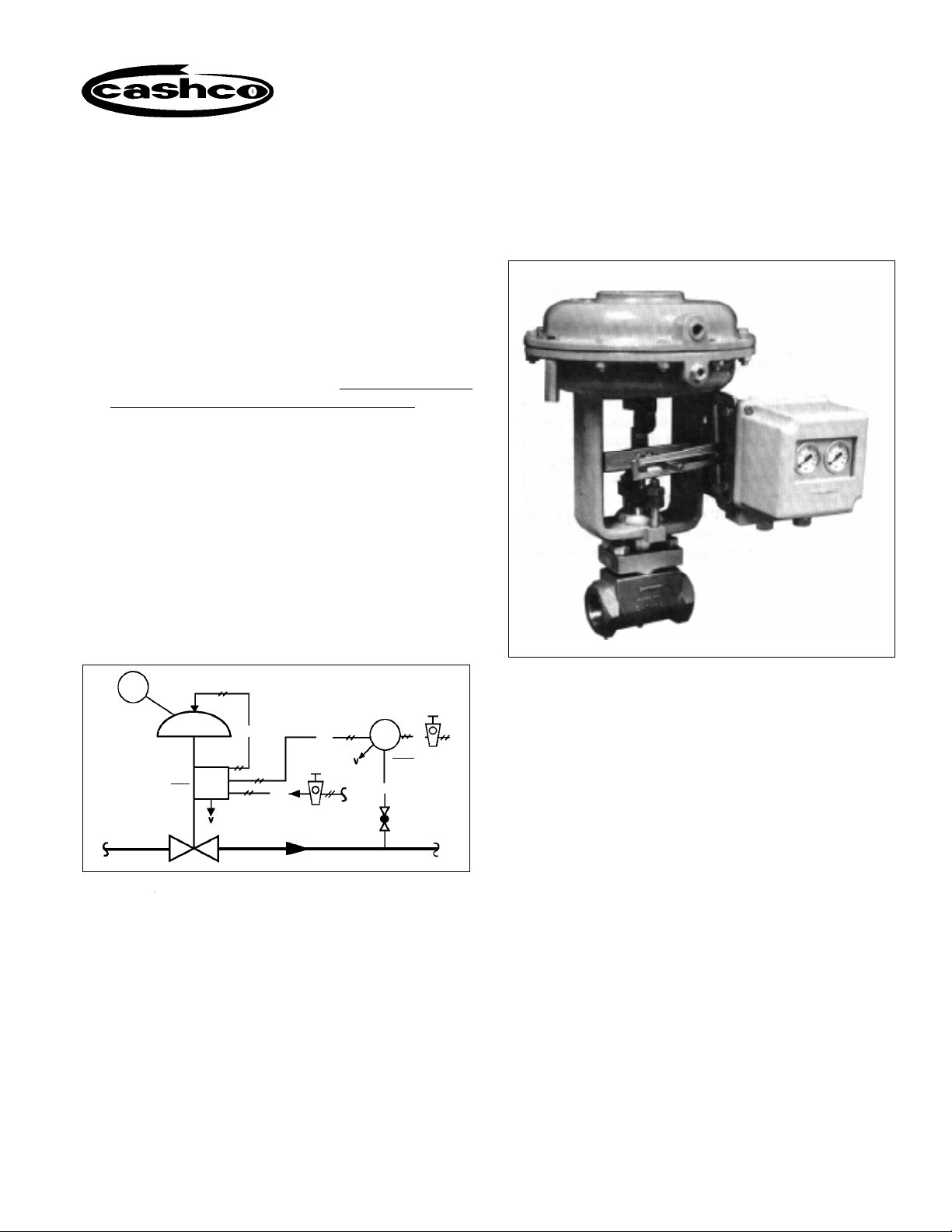
Model 9540L is a single acting, compact, force balance, pneumatic positioner used on linear travel (sliding stem) control valves. This positioner is utilized to
linearize the relationship between valve stem position
and the system’s control signal. This design is only
suitable for nominal 3-15 psig input signals, or split
range variations thereof.
Each unit comes complete with a set of built-in gages
within the internals; the cover includes a clear see-thru
panel to monitor gages. Gages monitor input “SIG”
and output “LOAD”.
IOM-9540L
06-99
SECTION I
The Model 9540L P/P positioner may be utilized with
the following current Cashco product models:
987 964 520 TFE SCV-30
988 2266 (2” size) 521 TFE
989 2296 SCV-S
PCV
5-13 psig
LOAD
3-15 psig
DIR.
P/P
P1 = 500 psig
Figure 1: Typical Pressure Reducing Pneumatic Control
ATO-FC
Loop - PCV with P/P Positioner
IAS
SIG
15-3 psig
PC
REV.
PROCESS
P2 = 100 psig
IAS
20 psig
IAS - Instrument Air Supply
PC - Pressure Controller
PCV - Pressure Control Valve
ATO-FC - Air-to-Open, Fail Close
ATC-FO - Air-to-Close, Fail Open
P/P - Pneumatic Input/Pneumatic Output
DIR - Direct Acting
REV - Reverse Acting
SIG - Controller Output Signal
V - Vent
CW - Clockwise rotation
CCW - Counter-clockwise rotation
SECTION II
II. METHOD OF OPERATION (See Figure 2)
The positioner operates with the force balance
principle: the input signal “SIG” (3-15 psig) acts on the
input diaphragm (50).The stroke of the input diaphragm is transferred to the flapper lever (38). The
resulting movement of the flapper varies the dynamic
pressure at the nozzle (51). This pressure acts on the
amplifier (53) and the change in output pressure
causes a movement of the actuator/valve stem.
This movement is back fed from the actuator/valve
stem (55) by the feedback lever (13) of the positioner,
and transferred to the stroke factor lever (19). The
stroke factor lever (19) is connected to the flapper
lever (38) by means of a range spring (41).
Page 2
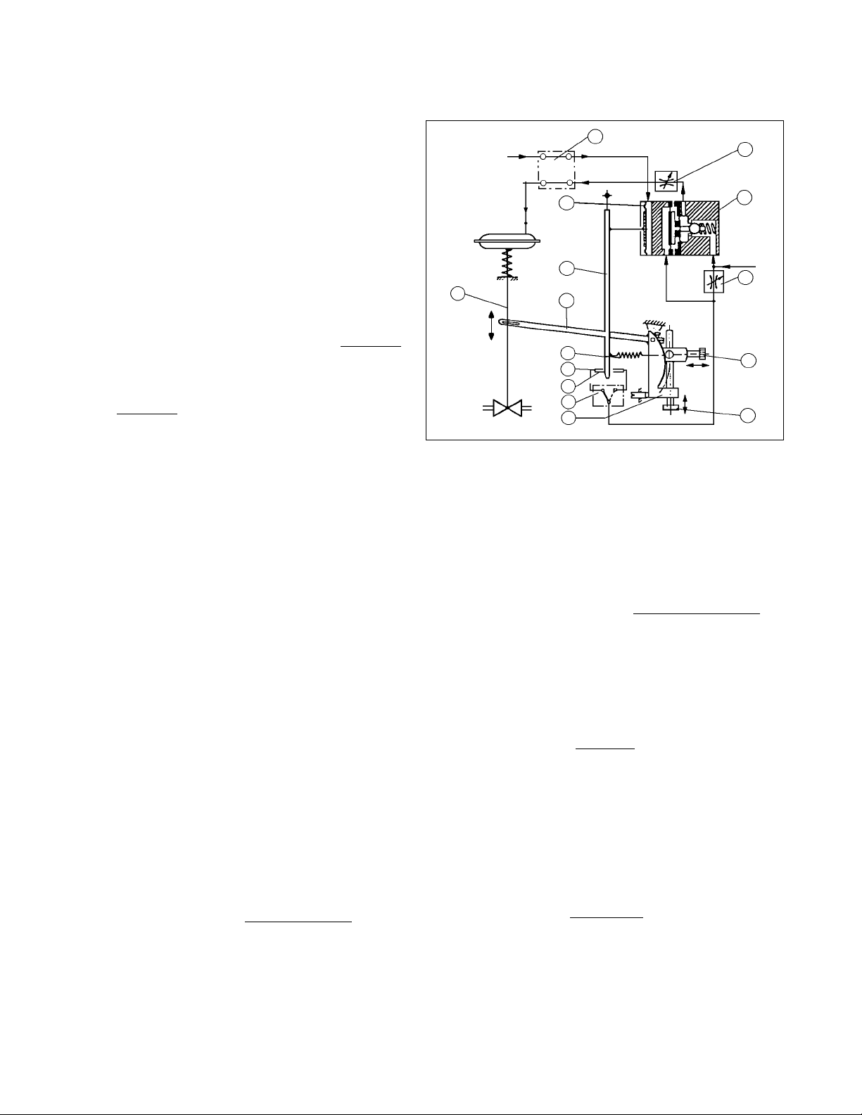
A force balance is created on the flapper lever (38)
when the force generated by the input diaphragm (50)
balances with the counter-force produced on the range
spring (41). This ensures that the actuator/valve stem
position is always proportional to the input signal.
Dynamic matching of the actuator (sensitivity, stability)
is factory set by means of the throttle screw (42) and
the damping throttles (44). The stroke range and zero
are set by means of the stroke factor thumbscrew (40)
and the zero thumbscrew (39). The changeover plate
(15) is used to set either an increasing or decreasing
output pressure for an increasing input signal, i.e.
direct or reverse acting.
The normal factory set position of the bypass switch (3)
is “EIN” (ON) (pointer at 6 o'clock), and the positioner
will be operational. If the positioner bypass switch (3)
is set to the “AUS” (OFF) position (pointer at 9 o’clock),
the input signal SIG is supplied direct to the actuator;
i.e. the positioner has no effect. Operation in the “AUS”
(OFF) position is only practical for control valves where
the positioner action is “Direct” and the actuator bench
range is approximately equal to the 3-15 psig “SIG”.
Use of bench ranges with upper limits greater than 15
psig will cause the control valve to not be able to fully
stroke when bypassed.
3
SIG
55
Travel
Figure 2: Single-acting positioner functional diagram.
On
LOAD
50
38
13
41
51
52
NU
15
19
44
53
IAS
42
39
40
III. MOUNTING TO SPRING DIAPHRAGM
ACTUATORS
A. The following text applies to field mounting of a
positioner.
B. Determining Mounting Side:
1. The action/failure position on the control valve
unitmust be known “Air-to-Open, Fail Closed”
(ATO-FC); or “Air-to-Close, Fail Open” (ATCFO). The mounting side is selected from Table
1 considering:
a.) Valve action/failure position
b.) Stem travel direction with increasing “SIG”
c.) Positioner action - Direct or Reverse
(Choose either steps 2a. -to- 3a.; or choose
steps 2b. -to- 3b.)
2a. On actuator yokes with a cast-on rib located
on one of the legs that support the lower
diaphragm housing, see representative crosssection Figure 3A. Rotate the actuator until
the rib with its mounting taps is located on the
side (right or left) as indicated in Table 1.
(Includes 987’s, 964’s and 2” 2266’s, 520 &
SECTION III
521 TFE’s with Models 55D, 55R, 115D and
115R actuators).
2b. The actuator yokes without a cast-on rib will
have four mounting holes on one of the yoke’s
legs. (See representative cross-section Figure 3B.) Rotate the actuator until the leg with
the four holes is on the side (right or left) as
indicated Table 1. (Includes 520 & 521 TFE’s
with Model 30 actuator.)
3a. On yokes with a rib, attach the positioner’s
mounting bracket (12) in accordance with the
dimensions of Figure 4 to the actuator
yoke. Use the center hole of the mounting
bracket (12) for attachment using the rib
mounting bracket (12) will give the proper
dimensions. (Figure 4 is shown as right-hand;
if left-hand is required, then dimensions are
mirror-imaged.)
3b. On yokes without a rib, attach the positioner’s
mounting bracket (12) in accordance with the
dimensions of Figure 4 to the actuator yoke.
Use two yoke mounting screws and nuts
(10B) and the two holes closest to the frontal
position when properly rotated. (Figure 4 is
shown as right-hand; if left-hand is required,
then dimensions are mirror imaged.)
IOM-9540L2
Page 3
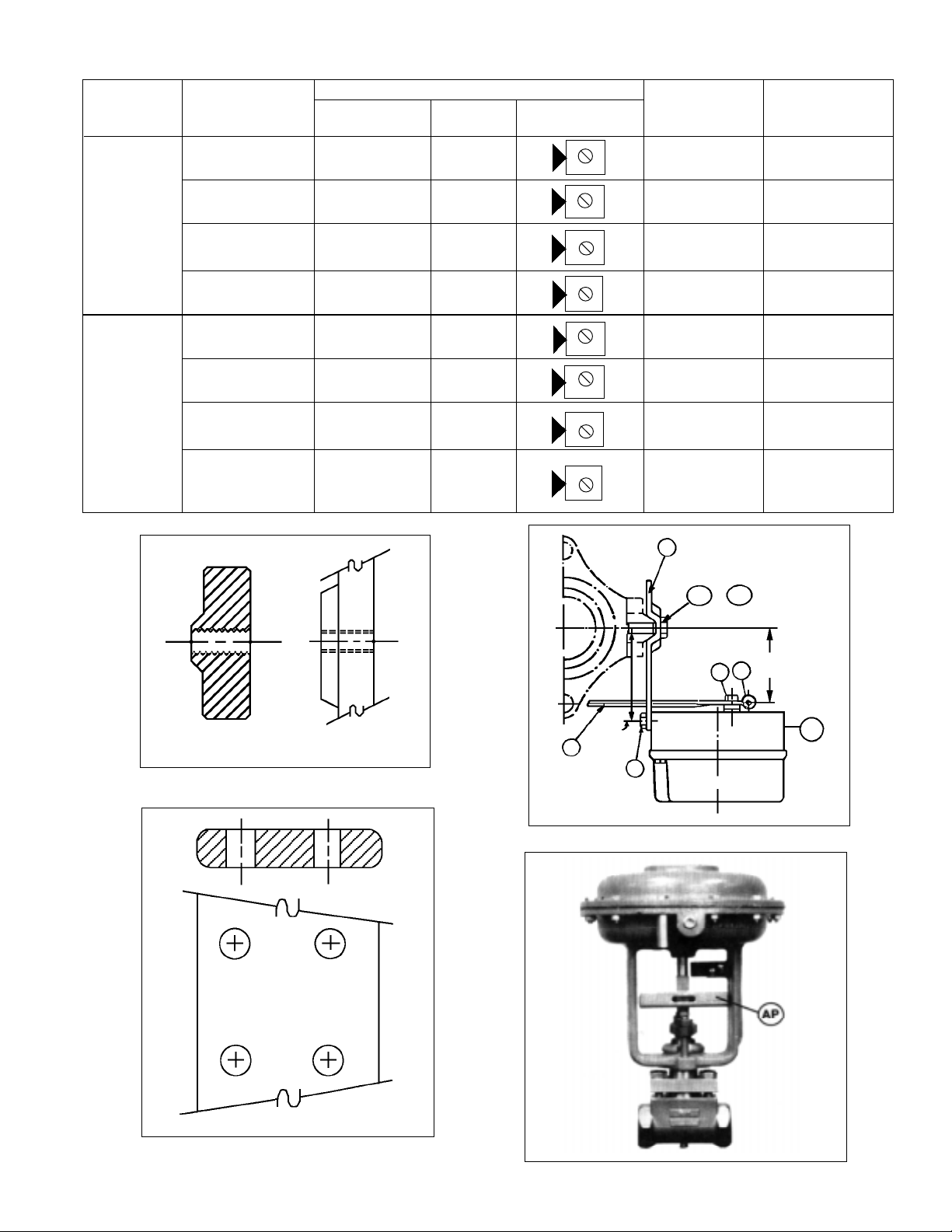
TABLE 1
CONTROL VALVE POSITIONER PLUG ACTION
CASHCO ACTION/FAIL MOUNTING ACTION CHANGEOVER STEM TRAVEL WITH SIGNAL
PRODUCT POSITION LOCATION PLATE SETTING DIRECTION INCREASING
2"- 2266 to Open
ATO-FC Right Direct Downwards Opens
N
U
& 964
(Non- ATC-FO Left Direct Downwards Closes
Reversible to Close
Actuator,
Reversible ATC-FO Right Reverse Downwards Opens
Trim) to Close
ATO-FC Left Reverse Downwards Closes
987, 988, ATO-FC Left Direct Upwards Opens
988MB, 989, to Open
N
U
N
U
N
U
N
U
to Open
520, 521,
SCV-S, ATC-FO Right Direct Upwards Closes
SCV-30 to Open
(Non-
Reversible ATC-FO Left Reverse Upwards Opens
Trim, to Open
N
U
N
U
Reversible
OR Non- ATO-FC Right Reverse Upwards Closes
Reversible to Open
N
U
Actuator)
12
10B
10A
or
CROSS-SECTION
Figure 3A
CROSS-SECTION
SIDE VIEW
2-1/8"
21
17
2-7/8"
13
11
BP
Figure 4
IOM-9540L
SIDE VIEW
Figure 3B
Figure 5A (Model 987)
3
Page 4
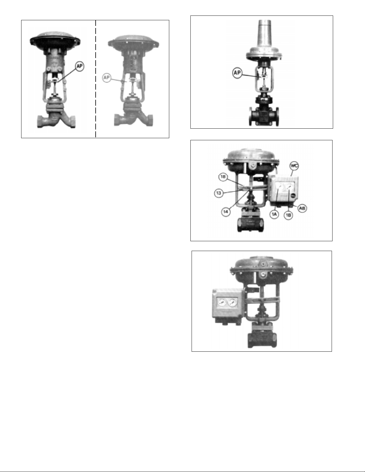
Figure 5B: (Model 964 w/left and right mounting positions)
4. If the control valve does not have an accessory
plate (AP) installed, the actuator stem must be decoupled from the valve stem. (Refer to the valve/
actuator instructions for de-coupling procedure.)
Place accessory plate (AP) as indicated in Figures 5A, 5B or 5C.
5. If it is necessary to re-orient an existing accessory
plate (AP) that is secured to the valve’s stem by a
jam nut, loosen the jam nut so that the accessory
plate (AP) is loosened enough that it can be tipped
and rotated to the proper frontal position. Retighten the accessory plate (AP) jam nut. Attach
the stem feedback carrier bolt (14) to the accessory plate (AP) using the Tinnerman nut.
(Note: Above is true for the 987 and 2296 actuators.
For Models 30, 55D, 55R, 115D and 115R actuators,
separate accessory plates are required for “left” or
“right” mounting positions.)
Figure 5C: (Model 521 w/Model 30 actuator)
Figure
6A
6. Remove the positioner cover (WC). Orient the unit
so that the DAMPING & GAIN labels are top/
center, and the gauges (1A & 1B) are right side up.
7. Fasten the positioner baseplate (BP) to the mounting bracket (12) using the two mounting screws
(11) (See Figure 4).
8. With the actuator at zero stroke (“LOAD” = 0 psig;
i.e. no air to actuator diaphragm), attach the
feedback lever (13) on the main shaft (17) (Figure
4) of the positioner with the feedback carrier bolt
(14) located in the feedback lever’s (13) slot. The
compensating spring (18) must be located above
the feedback carrier bolt (14) when the unit mounting is on the right (See Figure 6A), and below the
feedback carrier bolt (14) when the mounting is on
the left. (See Figure 6B). Hand tighten socket cap
screw (21) (Figure 4); DO NOT WRENCH
TIGHTEN!
Figure 6B
9. Press the stroke factor lever (19) (See Figure 7) of
the positioner’s internals against the travel stop
pin (20) and hold firmly in place. Place the #5 Allen
wrench into the head of the socket cap screw (21),
and tighten while still holding stroke factor lever
(19). Tighten firmly. (A 5 mm, #5 metric Allen
wrench should be provided with the unit.)
10. Install tubing fittings with acceptable thread sealant and tubing from the unit’s 1/4” NPT (female)
“OUTPUT 1” port of the adapter block(AB) up to
IOM-9540L4
Page 5

the connection port of the actuator casing.
NOTE-
Thread Sealants: If TFE tape is used, make sure
that small pieces of tape will not be “pinched off”
and enter the pneumatic internals. (Liquid thread
sealants are not recommended.)
11. Place temporary fittings and tubing so that the
positioner is able to be supplied with a 20-35 psig
air supply to the “SUPPLY AIR” port of the adapter
block (AB). Supply pressure depends upon actuator bench range; see Table 2. Using a manual
loader, connect a 3-15 psig air source to the
“INPUT (3-15 psig) W” port of the adapter block
(AB).
Actuator Supply Max Supply
Bench Setting Pressure Pressure
(psig) (psig) (psig)
3-15, 4-15
5-15, 3-10 20 25
8-15, 3-13
6-26, 6-27, 6-30
6-20, 7-28, 9-30 35 40
10-30, 16-30
TABLE 2
12. Stroke the valve thru its full travel by varying the
input signal “SIG” span of 3-15 psig. Observe the
feedback linkage to assure that the linkage does
not bind and does experience overtravel. At a 9
psig signal input, the feedback lever should be
approximately horizontal.
IMPORTANT NOTE: If the feedback lever (13) is
turned forcibly against the travel stop pin (20), the
stroke factor lever (19) will be released from rigid
connection (unscrews) to the positioner main shaft
(17). If this occurs, the feedback lever (13) must
be loosened, the main shaft (17) must be retightened to the stroke factor lever (19) by holding the
stroke factor lever (19) firmly against the travel
stop pin (20), while turning the main shaft (17) CW
(viewed from shaft end) using a screwdriver on the
main shaft’s (17) end. Steps 8 thru 11 must be
repeated.
13. Leave temporary air sources as installed for final
calibration, Section V, but turn off the air supply so
that no pressures are induced to the internals.
IV. BASIC ADJUSTMENTS/SETTINGS
A. Required Tools:
The following tools are required for the basic
adjustment:
1. Screwdriver
2. Open-end wrench - 6 mm
3. Feeler gauge 0.6 mm (.024 in)
4. (2) test gauges - 30 psig (for 20 psig max
bench range); (1) test gauge - 30 psig and
(1) test gauge - 60 psig (for 30 psig max bench
range)
5. Manual loader/airset
6. Open-end wrench - 10 mm
7. Needle-nose pliers; small
8. #5 Allen wrench (5 mm) (provided)
B. Manual Bypass Setting: (See Figure 7)
1. There are two positions for the pneumatic
bypass switch (3) to be in:
SECTION IV
2. “EIN” or “AUS” are labels cast into the baseplate
(BP). To bypass, loosen the bypass screw (2)CCW
to release the bypass switch (3) rotor; two full
revolutions of the bypass screw (20) will be required. Rotate the bypass switch (3) CW 90° to
move to bypass (AUS); rotate CCW to activate the
positioner (EIN). The bypass switch (3) has a rib
on its outer edge that indicates the position of the
bypass switch (3). When adjustments are completed, retighten bypass screw (2). DO NOT
LEAVE AT AN INTERMEDIATE POSITION;
PLACE AT “EIN” OR “AUS” ONLY.
NOTE: For picture clarity, all photographs hereafter have
the two internal gages removed.
IOM-9540L
“EIN”-Positioner is active (ON); this is the
factor set position.
“AUS” - Positioner is inactive (OFF), and the
input “SIG" is passed directly to the actuator,
bypassing the positioner internals.
Figure 7
5
Page 6

TABLE 3
Applicable Range Spring (41)
Valve Split Range Input Product
Stroke Input Signal: 3-15 psig Signals: 3-9, 9-15, 3-7, Size - Model
7-11 and 11-15 psig
P/N* Color Code P/N* Color Code
7/16" -08000- light yellow -08000- light yellow 1/2"-520 & 521 TFE's
1/2" -08000- " -08000- light yellow All sizes 987
9/16" -08000- " -08001- olive green 1" & 1-1/2" 964's
5/8" -08000- " -08001- " 1" 520 & 521 TFE's
3/4" -08000- " -08001- " 2" 2266
7/8" -08000- " -08001- " 2" 520 & 521 TFE's
1-1/8" -08001- olive green -08002- light gray 2" & 3" 964's
*Complete Part Number (P/N) is shown in Figure 8. Table 3 indicates the missing
nos. of the complete P/N. General P/N = 830-69-5-_ _ _ _ _-00.
C. Action Setting:
D. Range Spring Selection:
PART NO. COLOR COILS
light
gray
830-69-5-08002-00 7 -1/4
olive
green
830-69-5-08001-00 6 -3/4
light
yellow
830-69-5-08000-00 5 -3/4
Figure 8
1. Refer to Table 1 to see the graphical indicated
position of the changeover plate (15). The
indicator arrow is located on the edge of the
baseplate (BP). There are two positions for
this pneumatic switch to be in:
“N” - Direct action
“U” - Reverse action
2. The “N” and “U” are labels cast into the
surface of the changeover plate (15). If necessary, to change action loosen CP screw (4) to
removal. Lift the changeover plate (15) and its
CP gasket (16) and replace them to align the
label with the arrow as desired. Replace and
retighten changeover plate screw (4).
V. CALIBRATION/ADJUSTMENTS
A. ZERO AND STROKE Settings: (See Figure 9)
1. After settings of Section IV have been completed, place separate manual loaders to supply the positioner with air (“IAS”) and develop
a variable 3-15 psig signal (“SIG”) as the
input.
2. If the positioner has an input “SIG” of 3-15, 39 or 3-7 (i.e. full stroke is a 15 psig, 9 psig or
7 psig “SIG” respectively for REVERSE action), skip Step 3 following and go to Step 4.
3. If the positioner is split ranged for 9-15 or 1115 psig “SIG” input (i.e. zero stroke is at a 9
psig or 11 psig “SIG” respectively for DIRECT
action; full stroke is at a 9 psig or 11 psig
1. Each positioner unit is supplied with a colorcoded range spring (41). Figure 8 shows the
springs; identification is by the number of
coils. The range spring (41) to be utilized is
indicated above in Table 3.
2. To remove/change the range spring (41) see
Figure 9; hold stroke factor lever (19) against
the travel stop pin (20) and simultaneously
hold the zero thumbscrew (39). Using needle
nose pliers, remove the end of the range
spring (41) hooked to the flapper; then remove the opposite end from the zero mechanism. Reverse the procedure with the new/
different range spring (41). Always make sure
that the range spring’s (41) coils are closest
to the flapper lever (38).
3. After removal/change of the range spring
(41), recalibration is required. See Section V.
SECTION V
“SIG” respectively for REVERSE action), then
follow this procedure:
a. Shutoff supply air (“IAS”, i.e. 0 psig).
b. Release all tension on range spring (41)
by turning zero thumbscrew (39) CCW.
c. See Figure 4; loosen screw (21) securing
the feedback lever (13) on the backside of
the unit to the main shaft (17) using the #5
(5 mm) metric Allen wrench provided.
Manually move the stroke factor lever
(19) away from the tip of the stop pin (20)
a distance of approximately 1/4” - 3/8”
using some form of spacer; i.e. folded
cardboard, etc. Retighten feedback lever
(13) to main shaft (17). Remove the temporary 1/4” - 3/8” spacer.
IOM-9540L6
Page 7

Figure 9
d. Introduce an air supply (“IAS”) to the positioner as
required by Table 2.
e. Press the flapper lever (38) several times to the
left and right until the flappers are correctly aligned.
j. Repeat Steps e. and h. a minimum of three
times, as under this adjustment of Steps b.and
c. above, the STROKE and ZERO adjustments are mutually dependent; i.e. interacting.
k. If procedures of Step 3 above have been
completed, skip Step 4 following, and go to
next paragraph V.B.
4. Press the flapper lever (38) several times to the
left and right until the flappers are correctly aligned.
a. Induce the minimum value of the input signal
(“SIG”) using a manual loader. (This corresponds to the start of the valve’s stroke.)
b. Turn the zero thumbscrew (39) either CW or
CCW until the actuator begins to cause valve
stem travel. Precisely adjust to the point where
travel just begins.
c. Induce the maximum value of the input “SIG”.
(This corresponds to the end of the valve’s
stroke.)
f. Set the minimum input “SIG” with the manual
loader; i.e. 9 psig for 9-15 psig, 11 psig for 11-15
psig.
g. Turn zero thumbscrew (39) CW, increasing ten-
sion of range spring (41), until the actuator begins
to move away from its zero (shelf) position. (If
adjustment does not cause valve response, turn
off air supply (“IAS”) and return to 3.C. above;
increase the temporary spacer thickness in increments of 1/8” and repeat steps until the valve does
move). Care should be taken to assure that the
stroke factor lever (19) does not overtravel from
the starting point to the point where the stroke
factor lever (19) will hit the housing cover (WC),
before reaching its end position - approximately
39° rotation.
h. Induce the maximum input “SIG” with the manual
loader; i.e. 15 psig for 9-15 psig or 11-15 psig.
i. Turn the stroke factor thumbscrew (40) CW; this
shortens the valve stroke with respect to the “SIG”
change; i.e. less air pressure required to reach
valve’s maximum stroke position. Once valve
stem moves with each CW adjustment of the
stroke factor thumbscrew (40), reverse to CCW
rotation of stroke factor thumbscrew (40) and
precisely adjust up to the maximum stroke position of the control valve.
d. Turn the stroke factor thumbscrew (40) first
CCW until observing the shortening of the
valve’s stroke. Turn the stroke factor thumbscrew (40) CW until the valve travel is precisely at its full stroke.
e. Recheck the ZERO and STROKE
settings.They should be repeatable. Under
this procedure for adjustment, the ZERO and
STROKE calibrations are mutually independent (i.e. non-interacting, when the feedback
lever (13) and travel stop pin (20) are properly
installed and positioned.
B. Setting GAIN: (See Figure 10)
1. Increasing GAIN increases the sensitivity of the
positioner to a change in the input “SIG”. GAIN is
normally factory set when mounted by the factory,
and should not require field adjustment.
2. The open loop gain varies with the supply “IAS”
pressure, and the values represent linear amplification. Table 4 is a guide to the gain available for
each range spring (41) utilized:
TABLE 4
Supply Pressure Adjustable
(psig) Range
20 150:1
35 125:1
IOM-9540L
7
Page 8

3. A change in GAIN is normally indicated when
instability sluggishness shows up at steady
state operating conditions. If the positioner
output “LOAD” seems to rapidly oscillate (psstpsst-psst-...,) too much gain is present and
GAIN setting should be reduced until stability
is reached. If the positioner output “LOAD”
does not react to small changes in the “SIG”,
insufficient GAIN may be present; increase
GAIN until instability (psst-psst-psst-...) is
present, then reduce as described previously.
This procedure allows the gain of the control
loop to match the dynamic requirements of
the control system.
4. Determine whether GAIN should increase or
decrease based on above text. To increase
GAIN, rotate throttle screw (42) CW; to decrease GAIN, rotate throttle screw (42) CCW.
To prevent overadjustment the throttle screw
(42) is located within the limiting screw (43).
This allows the throttle screw (42) to only be
adjustable a total of approximately one revolution from maximum to minimum. Thus, GAIN
should be adjusted slowly in very small increments.
5. If GAIN is adjusted, ZERO resetting may be
required. Check and use Procedure V.A.
C. Setting DAMPING: (See Figure 10)
1. Increasing DAMPING introduces extra time
constant to the output “LOAD” of the positioner.
DAMPING should be increased/decreased
Figure 10
depending on the time observed for the positioner to respond to a large change in input
“SIG” during a non-steady state operating
condition.
2. DAMPING is factory set, and normally
requires minimal/no adjustment. However, if
determined as required, DAMPING is adjustable from a minimum - to - maximum ratio of
1:2.5. In its normal factory set position, the
damping screw (44) is set approximately flush
with the amplifier housing (53); this position is
minimum DAMPING. As the damping screw
(44) is screwed CW inwards, DAMPING increases. DAMPING may be increased by up
to approximately three full revolutions of the
damping screw (44), which will represent maximum DAMPING.
SECTION VI
VI. MAINTENANCE
A. Adjustment of the Positioner: (See Figure 11)
1. Component adjustment is only required when
the positioner has been disassembled or
sub-assemblies have been exchanged. All
settings performed in order to match the
positioner to the actuator are described in
Sections IV. and V.
2. See Section IV.A. for a list of required tools.
Figure 11
IOM-9540L8
Page 9

3. If adjustments are made with the positioner
mounted on the control valve, the feedback lever
(13) on the main shaft (17) of the positioner must
be loosened. (See Section III:8-9).
a. Set the changeover plate (15) to “N”.
4. The following procedure must be observed in
order to achieve a no-feedback adjustment of the
zero and stroke settings:
a. Press the stroke factor lever (19) against the
travel stop pin (20).
b. Turn the throttling screw (42) CW to its stops
(maximum GAIN).
c. Unhook the range spring (41) from the flapper
lever (38).
d. Check that the flappers (52) are aligned con-
centrically with the nozzles (51). If necessary
loosen the AMPLIFIER mounting screws on
the rear of the positioner and align the amplifier (53) sub-assembly accordingly.
e. Press the flapper lever (38) several times
alternately to the left and right, so that the balland-socket mounted flappers (52) are aligned
parallel to the nozzles (51).
f. Press the flapper lever (38) to the left. Set the
clearance between the right-hand nozzle (51)
and the right-hand flapper (52) to 0.6 mm
(0.024 in.) with the aid of feeler gauge by
turning the hexagonal adjuster (56) with a 6
mm wrench. Then secure the nut against
further turning using sealing paint.
g. Connect the positioner as shown in the test
circuit in Figure 12. Provide an “IAS” of 60
psig.
b. Set the stroke factor thumbscrew (40) to a
high stroke factor (approx. 5/64” before the
upper stop).
c. Turn the zero thumbscrew (39) until the out-
put pressure is 9 psig and make a note of this
value.
d. Set the stroke factor thumbscrew (40) to a low
stroke factor (approx. 5/64 before the lower
stop). The output pressure may not vary by
more than ± 0.003 psig as compared with the
setting described in c. above.
e. In case of excessive deviations the travel stop
pin (20) should be adjusted. Whenever the
travel stop pin (20) is adjusted, the settings
described in b. -to- d. should be repeated until
the deviation is less than ±0.003 psig.
f. Seal the travel stop pin (20) with sealing paint.
5. For mounting see Section III.
6. Return the changeover plate (15) to its original
position if it was “U”. Re-tighten the feedback (13)
lever onto the main shaft (17) of the positioner
(See Section III.B.8 & 9.).
h. Press the flapper lever (38) to the left. If the
I. Hook the range spring (41) onto the flapper
Test Gauge
IOM-9540L
output does not rise to the level of the supply
air pressure, either leaks are present of the
flapper (52) is not correctly aligned (repeat
e.).
lever (38), and provide a 9 psig input “SIG” to
port “Input (3-15) W” using a manual loader.
Test Gauge
See Table 2
for pressure
required
Output
2
LOAD
IAS
IAS
InputWOutput
MANUAL
LOADER/
AIRSET
1
SIG
3-15 psig
Figure 12
Supply Air
B. Cleaning The Throttle Screw: (See Figure 10)
1. Unscrew CCW the limiting screw (43). If you can’t
pull it out by hand, unscrew CCW the throttle
screw (42) and remove both by hand.
2. Pull the throttle screw (42) out of the limiting screw
(43).
3. Place the throttle screw (42) in a solvent (e.g.
benzene) and blow through it carefully. It is best to
clean in an ultrasonic solvent bath.
4. Turn the throttle screw (42) in again as far as it
goes CW.
5. Turn the limiting screw (43) in as far as it goes CW;
then back it out CCW about half a revolution.
6. Secure the limiting screw (43) with sealing paint.
9
Page 10

C. Replacing The Amplifier: (See Figure 13)
1. Unhook the range spring (41) from the flapper
lever (38). (See Figure 11.)
2. Unscrew and remove the amplifier (53) subassembly; the two amplifier mounting screws are
accessible from the rear of the positioner.
3. Install a new amplifier (53). Do not forget the
O-rings between the amplifier and the baseplate
(BP) (air baffle). Before tightening, carefully align
the mounting screws, position the amplifier (53) in
such a way that the flappers (52) are concentrically aligned with the nozzles (51).
4. Hook the range spring (41) onto the flapper lever
(38).
5. Perform a maintenance basic adjustment and
recalibrate per Sections IV, V and VI.
VII. TROUBLE SHOOTING GUIDE
1. Actuator does not respond to applied input signal.
Possible Causes Remedies
A. Amplifier defective A1. Replace amplifier (See VI.C.).
B. Pneumatic connections reversed B1. Check connections.
C. Feedback lever not tightened C1. Screw feedback lever tight (See III.B.9.).
D. Stroke factor lever is loose on the shaft D1. Tight shaft.
E. Positioner mounted on the wrong side E1. Check mounting side in accordance with table in Section III.
F. Changeover plate in the wrong orientation F1. Check setting accordance with table in Section III.
2. Output pressure does not reach its maximum.
Possible Causes Remedies
A. Amplifier throttle dirty A1. Remove and clean throttle (See VI.B.).
B. Supply air too low B1. Check supply air pressure.
C. Flappers not parallel with nozzles C1. Align flappers (See VI.A.d.-f.).
D. Supply air filter dirty D1. Replace filter.
Figure 13
SECTION VII
3. Actuator moves to end position.
Possible Causes Remedies
A. Positioner mounted on wrong side A1. Check mounting side in accordance with table in Section III.
B. Feedback lever not tightened B1. Tighten feedback lever.
C. Stroke factor lever loose on shaft C1. Tighten shaft (See Section III.B.).
IOM-9540L10
Page 11

4. Unstable behavior; non-steady state in control loop.
Possible Causes Remedies
A. Amplification too high A1. Reduce amplification.
B. Gland friction on the valve too high B1. Loosen gland packing somewhat or replace.
5. Stroke range cannot be adjusted.
Possible Causes Remedies
A. Wrong range spring A1. Replace range spring (See Section IV.D.).
B. Positioner does not completely reduce B1. Check supply air pressure.
pressure B2. Check amplification.
B3. Adjust clearance between nozzle and flapper.
6. Positioner makes “buzzing” noise
Possible Causes Remedies
A. Wrong action setting A1. Check position of the bypass switch and the action.
Change as required.
REPAIR PARTS KITS
KIT A: Includes gaskets, O-rings and small parts. Order P/N 295-08-5-07410-00.
KIT B: Replacement pneumatic amplifier. Order P/N 653-75-5-09542-00.
IOM-9540L
11
Page 12

Cashco, Inc.
P.O. Box 6
Ellsworth, KS 67439-0006
PH (785) 472-4461
FAX (785) 472-3539
E-mail: sales@cashco.com OR
exportsales@cashco.com
Printed in U.S.A. IOM-9540L bt
 Loading...