

Page 1
INSTALLATION, OPERATION AND MAINTENANCE MANUAL (IOM)
I. DESIGN AND FUNCTION:
IOM-8900
09-10
8900 Series
Emergency Relief Vents
Pressure Only or Pressure/Vacuum
SECTION I
The 8900 Series is classifi ed as an Emergency Relief
Vent (ERV). The design allows it to be used as an
emergency pressure only vent or a pressure/vacuum
vent. This Series of Vents can be constructed as top
guided or hinged design. Depending on the pressure
requirement, vents can be assembled using a stack
of weights or springs to achieve the desired set point
pressure.
The 8900 Series can provide emergency pressure
and vacuum relief beyond that furnished by the
normal pressure/vacuum vent for atmospheric and
low pressure tanks, as well as providing a convenient
access for tank cleaning, inspection and repair.
Emergency Pressure Relief Vents provide relief from
excessive internal pressure which may be caused
by an abnormal condition, such as ruptured internal
heating coils, an external fi re or a failure of the tank
blanketing system. Some Models are also design to
provide emergency vacuum relief as a result of loss
of pressure casued by a break in the tank wall or a
nozzle being dislodged from the base of the tank or
sudden cooling of the tank.
The 8900 Series provides an effective vapor
tight seal when the tank is not under emergency
conditions. If the tank outbreathing requirements
exceed the capacity of the normal pressure relief
vent, under emergency conditions, the pallet opens
to allow escape of the vapors, preventing damage
to the tank due to excessive pressure. The intergal
vacuum vent allows high fl owing relief from the same
unit.
This vent design is rugged but light weight for easy
handling, inspection and maintenance. For Models
8910 and 8920 removal of the pallet assembly allows
unobstructed access to the inside of the tank. For
Models 8930 and 8940 use handle to raise the
weighted pallet assembly and gain access to the
inside of the tank.
Product Selection Guide
Vent Function Guiding Model
Pressure Relief
Pressure/Vacuum Relief 8920
Pressure Relief
Pressure/Vacuum Relief 8940
Top Guided
(Spring Loaded)
Hinged
8910
8930
Page 2
SECTION II
II. INSTALLATION:
CAUTION
When installing any Valve Concepts venting device,
any safety regulations and procedures appropriate to
the specifi c plant site must be understood and followed
in accordance with that facilities corporate legal and
advisory policies.
CAUTION
DO NOT attempt to change pressure settings, either by
adding additional weight to the pallet assembly or by
changing the spring compression without consulting
the factory.
Handle the 8900 Series carefully to insure seat
tightness. Units could be damaged by over tightening
the studs or mounting it on a tank nozzle fl ange that
is not horizontal.
Carefully inspect the relief vent to insure that
there are no packing materials inside or around
the vent housing.
Before placing the vent on the tank nozzle, the fl ange
face on the tank and the vent should be inspected.
The standard vent is supplied with fl at face fl anges
and can mate with 150# ASME or API 650 fl anges.
The connecting fl anges must be fl at within 0.015”
(.381 mm), clean and free of scratches, corrosion
and any tool marks.
Inspect the gasket and make sure it is compatible
for the service. It is recommended to use a full
faced gasket to avoid defl ection of the body fl ange.
The vent should be installed using a wire cables
or straps connected to the lifting lugs/eyebolts (39)
located around the fl ange base. This will prevent
any damage to the hood.
Lubricate all studs and nuts with an appropriate
thread lubricant. If stainless steel fasteners are
used, select an anti-seize lubricant such as molydisulfi de.
Align the gasket with the bolt circle of the fl ange.
Lower the vent body carefully on the nozzle fl ange;
keep the gasket between the fl anges. Install the
studs and tighten the nuts by hand.
Using an alternating star pattern, tighten all the
fasteners to one-half recommended torque - see
Table 1. Make sure that the fl anges are not distorted
and that the gasket is evenly compressed. Finish
tightening fasteners to torque values in Table 1.
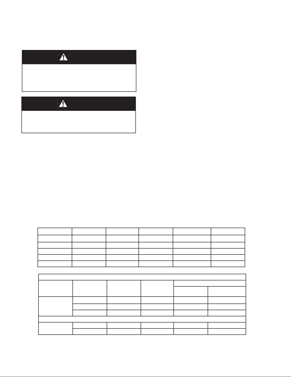
Gasket Dimensions
FLANGE TYPE O.D. in. I.D. in. B.C. in Bolt Hole in. Quantity
16” - 150# 23.50” 15.25’ 21.25” 1.13” 16
20 - 150#” 27.50” 19.25” 25.00” 1.25” 20
24” - 150# 32.00” 23.25” 29.50” 1.38” 20
20” - API 650 26.00” 19.25” 23.50” .75” 16
24” - API 30.00” 23.25” 27.50” .75” 20
TABLE 1
Flange
Type
150# ASME
API # 650
Size
16” 16 1.000 52 104
20” 20 1.125 63 110
24” 20 1.250 86 148
20” 20 0.625 35 53
24” 20 0.625 43 61
Qty
Holes
Bolt
(in)
(UNC)
Raised Face Flat Face
2
Torque (ft-lbs)
IOM-8900 Series
Page 3

III. MAINTENANCE:
SECTION III
The 8900 Series vents do not require any sort of
routine lubrication or adjustments, but should be
checked as part of a routine plant maintenance
program to confi rm that the vents are operating
properly. The ERV is a protection device and as
such will not normally cycle when in service.
In order to inspect the pallets and pallet diaphragms
for damage the vent must be removed from the tank
nozzle. Follow all safety guidelines your company
has to decommission a vent for inspection. Cashco/
Valve Concepts does not recommend that a vent be
removed from a tank in service due to the potental
of hazardous tank vapors or fl ammable tank vapors.
SECTION IV
IV. DISASSEMBLY of the 8910 and 8920 Guided - Spring Loaded Relief Vents:
See page 8 for a listing of parts. For Model 8910 (Figure 1) disregard item numbers 5 - 25, 28, 36, 40 - 60, 62
- 74 and 76. These parts are for vacuum service option for the Model 8920 and do not pertain to the pressure
only function of the 8910.
DISASSEMBLY FOR INSPECTION
To remove the vent from the tank nozzle, loosen
and remove the fl ange bolts and nuts from the tank
nozzle and fl ange seat (1). Attach lifting cables or
straps to the lifting lugs/eyebolts (39). Be sure to
utilize all lifting lugs in order to keep the unit stable
during lifting and transportion.
SPRING UNDER COMPRESSION. Relieve spring
com pres sion per following steps. Failure to do
so may result in fl ying parts that could cause
personal injury.
B. Removal of Vacuum Spring - 8920 Only:
WARNING
WARNING
SPRINGS UNDER COMPRESSION. Relieve spring
com pres sion per following steps. Failure to do so
may result in fl ying parts that could cause personal
injury.
A. Removal of Pressure Springs:
1. Place the vent fl ange (1) on a fl at work
surface. Measure the length of each compressed
spring (33) from the top surface of the pressure
pallet (3) to the top edge of the upper spring button
(34). Place a tag on each spring (33) and record
the height measurement for each. These values
will be required at re-assembly to reset the vent
spring pressure prior to installation.
2. Loosen and remove one “top” nut (35) from
each of the adjusting screws (31). Rotate remaining
nut (35) CCW evenly in 1/2” (13 mm) increments
to prevent unequal loads on the pallet/diaphragm
assembly. Continue this process until all nuts (35)
are removed.
3. Lift up to remove upper spring buttons (34)
(hole w/small I.D.) and springs (33).
1. Remove cap screws (28) from the weather
hood (11) and lift off upper spring canister (15).
Measure the length of the pallet stem (21), top edge
of stem to the top surface of the upper spring button
(14). Record this value. It will be required during reassembly to reset the vacuum range spring pressure
prior to installation.
Length of pallet stem ________
NOTE: DO NOT allow vacuum pallet assembly
(18) to fall as disassembly continues.
2. Rotate each nut (25) CCW one at a time to
remove and to release the compression of the spring
(16). NOTE: May need to grasp a section of the
threaded stem (21) with soft-jawed pliers to prevent
rotation of the pallet assembly (18). Maintain grip
on stem (21) while carefully lowering vacuum pallet
assembly (18) to rest on work surface below.
Lift up to remove upper vacuum spring button (14)
and spring (16).
NOTE: If vent was not supplied with a fl ame screen
(5) remove lower spring button (14) and lower spring
canister (13). If vent included a fl ame screen, before
removing button (14) and canister (13), draw match
“marks” between fl ange face of the lower spring
canister (13) and weather hood (11).
IOM-8900 Series
3
Page 4

C. Removal of Pressure Pallet Assembly:
1. Rotate nut (35) CCW three revolutions
on each adjusting screw (31) to loosen connection
between adjusting screw and pallet guide (30).
Grasp adjusting screws (31) with hand and rotate
each one CCW to remove adjusting screws and
travel stops (37).
2. Remove lower spring buttons (32) (hole w/
large I.D.). NOTE: Not necessary to remove pallet
guides (30) or guide pin (75). (Factory installed with
Loctite - torqued to 15 ft-lbs.)
3. Carefully lift the pallet assembly (3) up off
the fl ange seat (1), so not to damage the seating
surface. Inspect the seat surface for any damage
including but not limited to nicks and corrosion. If
damage is found, the seat should be relapped
or remachined to smooth fi nish. If remachining
is required, contact Cashco/Valve Concepts for
assistance.
D. Inspection of Diaphragms:
1. Position the pressure pallet assembly (3) on
a work bench with the diaphragm (2) side face up.
3. According to stack orientation of the
diaphragms E.1 previous, lay new diaphragms (2) in
the pallet (3) groove. Align holes in diaphragm (2)
bolt circle over studs (29) in the pressure pallet (3).
4. Position diaphragm retainer ring (4) over
studs (29) resting fl at against the diaphragms (2).
Install 1 lock washer (26) and 1 nut (27) to each stud
(29), tighten to 5 ft. lbs. NOTE: Do not allow studs
(29) to rotate and protrude out the backside of the
pallet (3), end point of studs should be fl ush.
NOTE: For Model 8910 Vents proceed to IV. H.
For Vacuum Pallet:
1. Place threaded end of pallet stem ( 21) in a
soft-jaw vise with pallet (18) face up.
2. Remove the cotter pin (56), nut (24), lock
washer (23), and the fl at washer (22).
3. Remove vacuum pallet (18) and diaphragm
(19). Clean pallet (18), especially the pallet groove
and inspect for nicks or sctatches. NOTE: Vacuum
pressure set point will dictate the quantity and stack
orientation of diaphragms. Record diaphragm’s
stack orientation for re-assembly.
2. Inspect the diaphragms (2,19) on both
pallet assemblies (if applicable) for any signs of
damage. Damages may include but are not limited
to tears, crinkles/creases, and holes. If it is deemed
that the diaphragm(s) need to be replaced, proceed
with following steps to replace. If they are deemed
to be in good condition, inspect the vacuum seat
ring (8) for similar damages as for the fl ange seat
(1) seating surface. These include but are not
limited to nicks and corrosion. If damage is found,
the seat surface may be relapped. If relapping the
seating surface does not create a suitable seating
surface, a new seat ring is required. Contact your
local representative for assistance. Provide Serial
Number, Product Code & Set Point Pressure(s) to
place an order for parts.
E. Diaphragm Replacment:
For Pressure Pallet:
1. Remove hex nuts (27), lock washers (26),
and diaphragm retainer ring (4) from the pallet.
NOTE: Pressure set point will dictate the quantity
and stack orientation of diaphragms. Record
diaphragm’s stack orientation for re-assembly.
4. Install new diaphragm(s) (19) over short
threaded end of stem (21) onto retainer plate (20).
Apply a light coat of TFE paste on the top surface
of the last diaphragm (19) around the edge of the
center hole.
5. Place vacuum pallet (18) with the machined
groove facing down on the diaphragm (19). Apply a
light coat of TFE paste to short threaded end of stem
(21).
6. Install fl at washer (22), lock washer (23)
and nut (24) onto the protruding threads of the stem
(21). Use a torque wrench to tighten nut to 15 ft-lbs.
7. Insert cotter pin (56) thru small hole in the
stem (21) and wrap prongs around stem.
F. Vacuum Seat Ring Replacement:
- For ERV without Flame Screen:
NOTE: Installation of the pressure pallet diaphragms
should be completed prior to installation of the
vacuum seat ring.
2. Remove diaphragm (2). Clean the pressure
pallet (3), especially the pallet groove, and inspect
for nicks or scratches.
4
1. Re-Orient the pressure pallet assembly (3)
with vacuum seat ring (8) face down - use 4” x 4”
blocks as support. DO NOT ALLOW DIAPHRAGM
(2) OR RETAINER RING (4) TO REST ON THE
BLOCKS.
IOM-8900 Series
Page 5

2. Rotate cap screws (36) CCW to remove
weather hood (11). Remove screen (6). Around
the bolt circle of the weather collar (7) place match
“marks” to indicate the location of each weather
hood support (10).
3. Rotate each support (10) CCW and remove.
Rotate seat ring nuts (73) CCW to remove nuts,
lockwashers (74), weather collar (7) and gasket (5).
of pallet stem (21) protrude thru upper spring button
(14). With other hand, thread one jam nut (25) on to
pallet stem (21).
NOTE: Check to ensure that as the pallet assembly
(18) is lifted upwards that the vacuum seat ring (8)
is centered and aligned with vacuum pallet (18)
assembly.
WARNING
4. Re-Orient the pressure pallet assembly (3)
with the seat ring (8) face up, again resting on the
blocks. Rotate cap screw (9) CCW and remove seat
ring (8) and seat ring gasket (5).
6. Clean sealing surfaces on seat ring (8) and
both sides of pressure pallet (3).
7. Install new seat ring gasket (5). Position
seat ring (8) on gasket (5), align holes and thread
cap screws (9) into pallet using a star pattern and
tighten to 15 ft. lbs.
8. Re-Orient the pressure pallet assembly (3)
with the seat ring (8) face down, again resting on the
blocks. Position new gasket (5) and weather collar
(7) over cap screws (9).
9. Using the “marks” per 2. previous, install the
weather hood supports (10) on the weather collar
and tighten to 15 ft-lbs.. On remaining cap screws,
install lock washers (74), nuts (73) and tighten to 15
ft-lbs..
10. Reposition the screen (6) around the
weather hood supports (10). Align holes in weather
hood (11) with holes in supports (10) and install cap
screws (36), torque to 15 ft-lbs. Install lower canister
(13) into weather hood (11).
11. From underside of pressure pallet (3)
assembly slide vacuum pallet (18) assembly threaded end of stem (21) fi rst, up through center
hole of lower canister (13).
12. Into the open end of the canister, install
lower spring button (14) and spring (16) over stem
(21) into the lower canister (13). Make sure that
lower spring coil rests inside the retainer groove of
the lower spring button (14).
13. Place upper spring button (14) on top of
vacuum spring (16). Make sure that top spring coil
rests inside the groove of the spring button.
SPRING UNDER COMPRESSION. Exercise caution to avoid accidental spring release. Vacuum
spring (16) is now under compression and the accidental release of force may result in fl ying parts
that could cause personal injury.
15. Continue to rotate jam nut (25) CW until
the height from the top of the pallet stem (21) to the
top of the upper spring button (14) is equal to the
value recorded per B.1. previous.
16. Thread a second jam nut (25) on pallet
stem (21). Secure tight against fi rst jam nut (25).
17. Place upper spring canister (15) over
vacuum spring (16), align bolt holes in canister
fl anges.
18. Insert cap screws (28) into fl ange bolt
holes and tighten snug - torque to 10 ft-lbs. NOTE:
DO NOT over tighten screws. Proceed to “H”.
G. Vacuum Seat Ring Replacement:
- For ERV with Flame Screen:
NOTE: Installation of the pressure pallet diaphragms
should be completed prior to installation of the
vacuum seat ring.
1. Orient the pressure pallet assembly (3) and
vacuum seat ring (8) face up. Note alignment of
the three cap screws in bottom of the lower spring
canister (13) with respect to the location of the cap
screws (9) around the weather collar (7). Place
match “marks” on fl ame screen (40) and on weather
collar (7) to indicate correct alignment of the fl ame
screen bolt holes during re-assembly of the fl ame
screen.
2. To dis-assemble fl ame screen from lower
spring canister (13) rotate three cap screws (28)
CCW and remove. NOTE: Support lower spring
canister (13) and lower spring button (14) from
below as cap screws are removed. They may fall
out of weather hood.
14. Place one hand on the upper spring button
(14) and compress the spring (16) until the threads
IOM-8900 Series
5
Page 6

3. Re-Orient the pressure pallet assembly (3)
with vacuum seat ring (8) face down - use 4” x 4”
blocks as support. DO NOT ALLOW DIAPHRAGM
(2) OR RETAINER RING (4) TO REST ON THE
BLOCKS.
4. Rotate cap screws (36) CCW to remove
weather hood (11). Remove screen (6). Around
the bolt circle of the weather collar (7) place match
“marks” to indicate the location of each weather
hood support (10).
5. Rotate each support (10) CCW and remove.
Rotate seat ring nuts (73) CCW to remove nuts,
lockwashers (74), weather collar (7), weather collar
(41) and fl ame screen (40).
6. Re-Orient the pressure pallet assembly (3)
with the seat ring (8) face up, again resting pressure
pallet on the blocks. Rotate cap screw (9) CCW and
remove seat ring (8) and seat ring gasket (5).
7. Clean sealing surfaces on seat ring (8) and
both sides of pressure pallet (3).
8. Install new seat ring gasket (5). Position
seat ring (8) on gasket (5), align holes and thread
cap screws (9) into pallet using a star pattern and
tighten to 15 ft. lbs.
9. Re-Orient the pressure pallet assembly (3)
with the seat ring (8) face down, again resting on the
blocks. Position fl ame screen (40), weather collar
gasket (41) and weather collar (7) over cap screws
(9). Ensure match marks are in alignment per G.1
and bolt holes.
14. From underside of pressure pallet assembly
slide vacuum pallet (18) assembly - threaded end of
stem (21) fi rst - up through the center hole of the
lower canister (13).
15. Install spring (16) over stem (21) and into
lower canister (13). Ensure that lower spring coil
rest inside the retainer groove of the lower spring
button (14).
16. Place upper spring button (14) on top of
vacuum spring (16). Make sure that top spring coil
rests inside the groove of the spring button.
17. Place one hand on the upper spring button
(14) and compress the spring (16) until the threads
of pallet stem (21) protrude thru upper spring button
(14). With other hand, thread one jam nut (25) on to
pallet stem (21).
NOTE: Check to ensure that as the pallet assembly
(18) is lifted upwards that the vacuum seat ring (8)
is centered and aligned with vacuum pallet (18)
assembly.
WARNING
SPRING UNDER COMPRESSION. Exercise caution to avoid accidental spring release. Vacuum
spring (16) is now under compression and the accidental release of force may result in fl ying parts
that could cause personal injury.
18. Continue to rotate jam nut (25) CW until
the height from the top of the pallet stem (21) to the
top of the upper spring button (14) is equal to the
value recorded per B.1. previous.
10. Using the “marks” per G.4. previous, install
the weather hood supports (10) on the weather collar
and tighten to 15 ft-lbs. On remaining cap screws
install lock washers (74), nuts (73) and tighten to 15
ft-lbs.
11. Reposition the screen (6) around the
weather hood supports (10). Align holes in weather
hood (11) with holes in supports (10) and install cap
screws (36), torgue to 15 ft-lbs.
12. With open end up, install lower spring
button (14) into lower canister (13) and position both
through the weather hood (11).Ensure alignment of
holes between fl ame screen (40), lower canister
(13) and lower spring button (14).
13. From below the pressure pallet assembly
(3) insert three cap screws to secure fl ame screen to
lower canister and spring button - tighten to 10 ft-lbs.
6
19. Thread a second jam nut (25) on pallet
stem (21). Secure tight against fi rst jam nut (25).
20. Place upper spring canister (15) over
vacuum spring (16), align bolt holes in canister
fl anges.
21. Insert cap screws (28) into fl ange bolt
holes and tighten snug - torque to 10 ft-lbs. NOTE:
DO NOT over- tighten cap screws.
H. Re-assemble Pallet to Flange Seat:
1. Lift pallet (3) sub-assembly up to a suffi cient
height to pass over tops of pallet guides (30). Lower
sub-assembly coming to rest on the fl ange seat (1).
NOTE: Check to ensure that as the pallet assembly
(3) is lowered, the fl ange seat (1) is centered and
aligned with pressure pallet (3) assembly.
IOM-8900 Series
Page 7

2. With open end up, place lower pressure
spring buttons (32) (hole with large I.D.) over pallet
guides (30) coming to rest on pressure pallet.
6. Place upper pressure spring buttons (34)
on springs (33), make sure springs are seated in the
spring button retaining groove.
3. Position travel stops (37) on top of pallet
guides (30) and thread adjusting screw (31) thru
stops and into top of pallet guides (30) hand tighten.
Make sure that adjusting screws (31) threads are
engaged fully into the pallet guides (30).
4. Rotate nuts (35) CW and wrench tighten
against travel stops (37).
5. Slide pressure springs (33) over adjusting
screws (31), make sure springs are seated in the
spring button retaining groove.
7. Thread one jam nut (35) CW onto each
adjusting screw (31). Recalling the values recorded
for the compressed height of each spring per A.1.
previous; continue to rotate jam nuts CW using a star
pattern until the height from the top of the pressure
pallet (3) to the top of the upper spring button (34) is
equal to the recorded value for each spring.
8. Thread a second jam nut (35) onto each
adjusting screw (31) tighten two nuts against each
other.
SECTION V
V. INSPECTION / DIAPHRAGM REPLACEMENT for 8930 and 8940 Hinged - Relief Vents:
See page 14 for a listing of parts. For Model 8930 (Figure 3) disregard item numbers 5 - 8, 10 - 16, 18 - 24, 28,
40, 56, and 73 - 74. These parts are for vacuum service option for the Model 8940 and do not pertain to the
pressure only function of the 8930.
To remove the vent from the tank nozzle, loosen
and remove the fl ange bolts and nuts from the tank
nozzle and fl ange seat (1). Attach lifting cables or
straps to the lifting lugs/eyebolts (39). Be sure to
utilize all lifting lugs in order to keep the unit stable
during lifting and transportion. Place the vent fl ange
(1) on a fl at work surface.
B. Diaphragm Replacment:
1. Remove hex nuts (27), lock washers (26),
and diaphragm retainer ring (4) from the pallet.
NOTE: Pressure set point will dictate the quantity
and stack orientation of diaphragm(s). Record
diaphragm’s stack orientation for re-assembly.
Model 8930 & 8940:
A. Inspection of Pressure Pallet Diaphragm:
1. Grasp handle (70), lift up to raise and open
the weighted pallet assembly.
2. Inspect the diaphragm(s) (2) on the
pressure pallet assembly for any signs of damage.
Damages may include but are not limited to tears,
crinkles/creases, and holes. If it is deemed that
the diaphragm need to be replaced, proceed with
following steps to replace. If the seating surface
(1) is damaged, the seat surface may need to be
relapped. If relapping the seating surface does not
create a suitable seating surface, a new fl ange seat
(1) is required. Contact your local representative for
assistance. Provide Serial Number, Product Code &
Set Point Pressure(s) to place an order for parts.
IOM-8900 Series
2. Remove diaphragm(s) (2). Clean the
pressure pallet (3), especially the pallet groove, and
inspect for nicks or scratches.
3. According to stack orientation of the
diaphragms B.1 previous, position new diaphragm(s)
(2) in the pallet (3) groove. Align holes in diaphragm
(2) bolt circle over the cap screws (49) in the pressure
pallet (3).
4. Position diaphragm retainer ring (4) over
cap screws (49). Install 1 lock washer (26) and 1 nut
(27) to each cap screw (49), tighten all nuts to 5 ft.
lbs.
5. Close the pressure pallet assembly. Return
to Section II for Installation.
7
Page 8

Model 8940:
A. Inspection/Replacement of Vacuum
Pallet Diaphragm:
SPRING UNDER COMPRESSION. Relieve spring
com pres sion per following steps. Failure to do
so may result in fl ying parts that could cause
personal injury.
1. Remove cap screws (28) from the weather
hood (11) and lift off upper spring canister (15).
Measure the length of the pallet stem (21), top edge
of stem to the top surface of the upper spring button
(14). Record this value. It will be required during reassembly to reset the vacuum range spring pressure
prior to installation.
WARNING
Length of pallet stem ________
7. Install new diaphragm(s) (19) over short
threaded end of stem (21) onto retainer plate (20).
Apply a light coat of TFE paste on the top surface
of the last diaphragm (19) around the edge of the
center hole.
8. Place vacuum pallet (18) with the machined
groove facing down on the diaphragm (19). Apply a
light coat of TFE paste to short threaded end of stem
(21).
9. Install fl at washer (22), lock washer (23)
and nut (24) onto the protruding threads of the stem
(21). Use a torque wrench to tighten nut to 15 ft-lbs.
10. Insert cotter pin (56) thru small hole in the
stem (21) and wrap prongs around stem.
B. Vacuum Seat Ring Replacement For ERV with Counter Weight Design:
NOTE: DO NOT allow vacuum pallet assembly
(18) to fall as disassembly continues.
2. Rotate each nut (25) CCW one at a time to
remove and to release the compression of the spring
(16). NOTE: May need to grasp a section of the
threaded stem (21) with soft-jawed pliers to prevent
rotation of the pallet assembly (18). Maintain grip
on stem (21) while carefully lowering vacuum pallet
assembly (18) to rest on work surface below.
Lift up to remove upper vacuum spring button (14)
and spring (16).
NOTE: If vent was not supplied with a fl ame screen
(5) remove lower spring button (14) and lower spring
canister (13). If vent included a fl ame screen, before
removing button (14) and canister (13), draw match
“marks” between fl ange face of the lower spring
canister (13) and weather hood (11).
3. Lift handle (70) up to raise the weighted
pallet assembly and remove the vacuum pallet
assembly (18).
4. Place threaded end of pallet stem ( 21) in a
soft-jaw vise with pallet (18) face up.
5. Remove the cotter pin (56), nut (24), lock
washer (23), and the fl at washer (22).
6. Remove vacuum pallet (18) and diaphragm
(19). Clean pallet (18), especially the pallet groove
and inspect for nicks or sctatches. NOTE: Vacuum
pressure set point will dictate the quantity and stack
orientation of diaphragms. Record diaphragm’s
stack orientation for re-assembly.
CAUTION
Use overhead support and sling to secure Counter
Weight. Failure to do so may result in falling parts
that could cause personal injury.
1. Attach sling and overhead support around
counter weight (58). Remove cotter pins (57) and
slide cables (17) off ends of pin (50).
2. Pull pin (50) out of pivot arm assembly
(46), spacers (51) and weight arm (47). Set counter weight assembly and parts aside.
3. Rotate nuts (55) CCW and remove. Push
hinge pin (52) through pivot arm assembly (46).
Lift pallet and vent hood assembly up to remove
from fl ange seat (1) assembly.
4. Proceed to Step D. or E.
C. Vacuum Seat Ring Replacement For ERV with Stack Weight Design:
1. Rotate top nuts (36) CCW and remove
nuts, lock washers (68) and fl at washers (67).
2. Lift up to remove stack of pressure weights
(64). Maintain stack orientation, do not remove or
add any weight that will change the factory calibarated pressure setpoint.
3. Rotate nuts (55) CCW and remove. Push
hinge pin (52) through pivot arm assembly (46).
Lift pallet and vent hood assembly up to remove
from fl ange seat (1) assembly.
8
IOM-8900 Series
Page 9

4. Rotate lower jam nuts (36) CCW two three revolutions to loosen from weather hood.
Rotate weight studs CCW and remove from top of
weatherhood.
11. From underside of pressure pallet (3)
assembly slide vacuum pallet (18) assembly threaded end of stem (21) fi rst, up through center
hole of lower canister (13).
4. Proceed to Step D. or E.
D. Vacuum Seat Ring Replacement:
- For ERV without Flame Screen:
1. Position the pressure pallet assembly (3)
with vacuum seat ring (8) face down - use 4” x 4”
blocks as support. DO NOT ALLOW DIAPHRAGM
(2) OR RETAINER RING (4) TO REST ON THE
BLOCKS.
2. Rotate cap screws (36) CCW to remove
weather hood (11). Remove screen (6). Around
the bolt circle of the weather collar (7) place match
“marks” to indicate the location of each weather
hood support (10).
3. Rotate each support (10) CCW and remove.
Rotate seat ring nuts (73) CCW to remove nuts,
lockwashers (74), weather collar (7) and gasket (5).
4. Re-Orient the pressure pallet assembly
(3) with the seat ring (8) face up, again resting on
the blocks. Rotate cap screw (9) CCW and remove
seat ring (8) and seat ring gasket (5).
6. Clean sealing surfaces on seat ring (8) and
both sides of pressure pallet (3).
7. Install new seat ring gasket (5). Position
seat ring (8) on gasket (5), align holes and thread
cap screws (9) into pallet using a star pattern and
tighten to 15 ft. lbs.
8. Re-Orient the pressure pallet assembly (3)
with the seat ring (8) face down, again resting on the
blocks. Position new gasket (5) and weather collar
(7) over cap screws (9).
9. Using the “marks” per 2. previous, install the
weather hood supports (10) on the weather collar
and tighten to 15 ft-lbs.. On remaining cap screws,
install lock washers (74), nuts (73) and tighten to 15
ft-lbs.
10. Reposition the screen (6) around the
weather hood supports (10). Align holes in weather
hood (11) with holes in supports (10) and install
studs/jam nuts or cap screws (36), torque to 15 ftlbs. Install lower canister (13) into weather hood
(11).
12. Into the open end of the canister, install
lower spring button (14) and spring (16) over stem
(21) into the lower canister (13). Make sure that
lower spring coil rests inside the retainer groove of
the lower spring button (14).
13. Place upper spring button (14) on top of
vacuum spring (16). Make sure that top spring coil
rests inside the groove of the spring button.
14. Place one hand on the upper spring button
(14) and compress the spring (16) until the threads
of pallet stem (21) protrude thru upper spring button
(14). With other hand, thread one jam nut (25) on to
pallet stem (21).
NOTE: Check to ensure that as the pallet assembly
(18) is lifted upwards that the vacuum seat ring (8)
is centered and aligned with vacuum pallet (18)
assembly.
WARNING
SPRING UNDER COMPRESSION. Exercise caution to avoid accidental spring release. Vacuum
spring (16) is now under compression and the accidental release of force may result in fl ying parts
that could cause personal injury.
15. Continue to rotate jam nut (25) CW until
the height from the top of the pallet stem (21) to the
top of the upper spring button (14) is equal to the
value recorded per A.1. previous.
16. Thread a second jam nut (25) on pallet
stem (21). Secure tight against fi rst jam nut (25).
17. Place upper spring canister (15) over
vacuum spring (16), align bolt holes in canister
fl anges.
18. Insert cap screws (28) into fl ange bolt
holes and tighten snug - torque to 10 ft-lbs. NOTE:
DO NOT over tighten screws.
Proceed to F. or G.
E. Vacuum Seat Ring Replacement:
- For ERV with Flame Screen:
NOTE: Installation of the pressure pallet diaphragms
should be completed prior to installation of the
vacuum seat ring.
IOM-8900 Series
9
Page 10

1. Orient the pressure pallet assembly (3) and
vacuum seat ring (8) face up. Note alignment of the
three cap screws (28) in bottom of the lower spring
canister (13) with respect to the location of the cap
screws (9) around the weather collar (7). Place
match “marks” on fl ame screen (40) and on weather
collar (7) to indicate alignment of the fl ame screen
bolt holes during re-assembly of the fl ame screen.
2. To dis-assemble fl ame screen from lower
spring canister (13) rotate three cap screws (28)
CCW and remove. NOTE: Support lower spring
canister (13) and lower spring button (14) from
below as cap screws are removed. They may fall
out of weather hood.
3. Re-Orient the pressure pallet assembly (3)
with vacuum seat ring (8) face down - use 4” x 4”
blocks as support. DO NOT ALLOW DIAPHRAGM
(2) OR RETAINER RING (4) TO REST ON THE
BLOCKS.
11. Reposition the screen (6) around the
weather hood supports (10). Align holes in weather
hood (11) with holes in supports (10) and install
studs/jam nuts or cap screws (36), torgue to 15 ftlbs.
12. With open end up, install lower spring
button (14) into lower canister (13) and position both
through the weather hood (11).Ensure alignment of
holes between fl ame screen (40), lower canister
(13) and lower spring button (14).
13. From below the pressure pallet assembly
(3) insert three cap screws (28) to secure fl ame
screen (40) to lower canister (13) and lower spring
button (14) - tighten to 10 ft-lbs.
14. From underside of pressure pallet assembly
slide vacuum pallet (18) assembly - threaded end of
stem (21) fi rst - up through the center hole of the
lower canister (13).
4. Rotate cap screws (36) CCW to remove
weather hood (11). Remove screen (6). Around
the bolt circle of the weather collar (7) place match
“marks” to indicate the location of each weather
hood support (10).
5. Rotate each support (10) CCW and remove.
Rotate seat ring nuts (73) CCW to remove nuts,
lockwashers (74), weather collar (7), weather collar
(41) and fl ame screen (40).
6. Re-Orient the pressure pallet assembly (3)
with the seat ring (8) face up, again resting pressure
pallet on the blocks. Rotate cap screw (9) CCW and
remove seat ring (8) and seat ring gasket (5).
7. Clean sealing surfaces on seat ring (8) and
both sides of pressure pallet (3).
8. Install new seat ring gasket (5). Position
seat ring (8) on gasket (5), align holes and thread
cap screws (9) into pallet using a star pattern and
tighten to 15 ft. lbs.
9. Re-Orient the pressure pallet assembly (3)
with the seat ring (8) face down, again resting on the
blocks. Position fl ame screen (40), weather collar
gasket (41) and weather collar (7) over cap screws
(9). Ensure match marks are in alignment per E.1
and bolt holes.
10. Using the “marks” per E.4. previous, install
the weather hood supports (10) on the weather collar
and tighten to 15 ft-lbs. On remaining cap screws
install lock washers (74), nuts (73) and tighten to 15
ft-lbs.
10
15. Install spring (16) over stem (21) and into
lower canister (13). Ensure that lower spring coil
rest inside the retainer groove of the lower spring
button (14).
16. Place upper spring button (14) on top of
vacuum spring (16). Make sure that top spring coil
rests inside the groove of the spring button.
17. Place one hand on the upper spring button
(14) and compress the spring (16) until the threads
of pallet stem (21) protrude thru upper spring button
(14). With other hand, thread one jam nut (25) on to
pallet stem (21).
NOTE: Check to ensure that as the pallet assembly
(18) is lifted upwards that the vacuum seat ring (8)
is centered and aligned with vacuum pallet (18)
assembly.
WARNING
SPRING UNDER COMPRESSION. Exercise caution to avoid accidental spring release. Vacuum
spring (16) is now under compression and the accidental release of force may result in fl ying parts
that could cause personal injury.
18. Continue to rotate jam nut (25) CW until
the height from the top of the pallet stem (21) to the
top of the upper spring button (14) is equal to the
value recorded per A.1. previous.
19. Thread a second jam nut (25) on pallet
stem (21). Secure tight against fi rst jam nut (25).
IOM-8900 Series
Page 11

20. Place upper spring canister (15) over
vacuum spring (16), align bolt holes in canister
fl anges.
21. Insert cap screws (28) into fl ange bolt
holes and tighten snug - torque to 10 ft-lbs. NOTE:
DO NOT over- tighten cap screws.
Proceed to F or G.
arm (47). Slip cables (17) over pin (50) ends and
install cotter pins (57).
G. Assemble Pallet Assembly & Stack
Weights to Flange Seat Assembly:
1. Place pallet assembly on fl ange seat (1).
Align pivot arm (46) with hinge (60) and insert hinge
pin (52). Install nut (55).
F. Assemble Pallet Assembly & Counter
Weight to Flange Seat Assembly:
1. Place pallet assembly on fl ange seat (1).
Align pivot arm (46) with hinge (60) and insert hinge
pin (52). Install nut (55).
2. Use overhead support and sling to lift
counter weight (58). Align hole in weight arm (47)
with pin hole in arm assembly (46). Press pin (50)
through arm assembly (46), spacers (51) and weight
2. Position stack weights (64) over studs on
top of jam nuts in vent hood (11). Maintain stack
orientation, do not remove or add any weight that
will change the factory calibrated pressure setpoint.
3. Install fl at washers ( 67), lock washers (68)
and hex nuts (36). Torque to 15 ft.-lbs.
SECTION VI
VI. ORDERING INFORMATION:
NEW REPLACEMENT UNIT vs PARTS "KIT" FOR FIELD REPAIR
To obtain a quotation or place an order, please retrieve the Serial Number and Product Code that was
stamped on the metal name plate and attached to the unit. This information can also be found on the Bill of
Material (parts list) that was provided when unit was originally shipped.) (Serial Number typically 6 digits).
NEW REPLACEMENT UNIT:
PARTS "KIT" for FIELD REPAIR:
Contact your local Cashco, Inc., Sales Rep re sen ta tive with the Serial Number, Product code and the
pressure / vacuum settings. With this information
they can provide a quotation for a new unit including
a complete description, price and availability.
CAUTION
Do not attempt to alter the original construction of any
unit without assistance and approval from the factory.
All purposed changes will require a new name plate with
appropriate ratings and new product code to accomodate the recommended part(s) changes.
IOM-8900 Series
Contact your local Cashco, Inc., Sales Rep re sen ta tive with the Serial Number , Product code
and Pressure / Vacuum settings. Identify the
parts and the quantity required to repair the unit
from the Bill of Materials sheet that was provided
when unit was originally shipped.
NOTE: Those part numbers that have a quantity
indicated under "Spare Parts" in column "A”
refl ect minimum parts required for inspection
and rebuild, - "Soft Goods Kit". Those in column “B” include minimum trim replacement
parts needed plus those "Soft Goods" parts
from column "A".
If the "BOM" is not available, refer to the crosssectional drawings included in this manual for
part identifi cation and selection.
Local Sales Representative will provide quotation for appropriate Kit Number, Price and
Availability.
11
Page 12

MODEL 8910 PRESSURE ERV
Top Guided - Spring
Figure 1
12
ITEM NO. DESCRIPTION ITEM NO. DESCRIPTION
1. Flange Seat 23. Lock Washer
2. Press. Pallet Diaphragms * 24. Finsh Nut
3. Pressure Pallet 25. Jam Nut
4. Diaphragm Retainer (Press.) 26. Lock Washer
5. Seat Ring Gaskets * 27. Nut
6. Screen 28. Cap Screw
7. Weather Collar 29. Stud
8. Seat Ring 30. Pallet Guide
9. Cap Screw 31. Adjusting Screw
10. Weather Hood Support 32. Lower Press. Spring Button
11. Weather Hood 33. Pressure Spring
12. Rivet Nut 34. Upper Press. Spring Button
13. Lower Spring Canister 35. Jam Nut
14. Vacuum Spring Button 36. Cap Screw
15. Upper Spring Canister 37. Travel Stop
16. Vacuum Spring 38. Jam Nut
17. Stablizer Cable 39. Eye Bolt
18. Vacuum Pallet 40. Flame Screen
19. Vacuum Pallet Diaphragm * 41. Weather Collar Gasket *
20. Diaphragm Retainer (Vac.) 56. Cotter Pin
21. Pallet Stem 73. Seat Ring Nut
22. Flat Washer 74. Seat Ring Lock Washer
* Recommended Spare Parts 75. Pallet Guide Pin
61. Hinge Bolt (Not Shown)
IOM-8900 Series
Page 13

MODEL 8920 PRESSURE/VACUUM ERV
Top Guided - Spring
Figure 2
IOM-8900 Series
13
Page 14

MODEL 8930 PRESSURE ERV
Hinged Design
Figure 3
ITEM NO. DESCRIPTION ITEM NO. DESCRIPTION
1. Flange Seat 43. Pallet Swival
2. Press. Pallet Diaphragms * 44. Shoulder Screw - Pivo Clip
3. Pressure Pallet 45. Plain Washer - Pivo Clip
4. Diaphragm Retainer (Press.) 46. Pin Arm Assembly
5. Seat Ring Gaskets * 47. Weight Arm
6. Screen 48. Strap
7. Weather Collar 49. Cap Screw
8. Seat Ring 50. Pin - Counter Weight
9. Cap Screw 51. Spacer _ Weight Arm
10. Weather Hood Support 52. Hinge Pin
11. Weather Hood 53. Lock Washer - Pivot Clip
12. Rivet Nut 54. Cap Screw - Pivot Clip
13. Lower Spring Canister 55. Hex Nut - Hinge Pin
14. Vacuum Spring Button 56. Cotter Pin - Vacuum Pallet
15. Upper Spring Canister 57. Cotter Pin - Counter Wt. Pin
16. Vacuum Spring 58. Counter Weight (SST)
17. Stablizer Cable 59. Counter Weight (Lead)
18. Vacuum Pallet 60. Hinge
19. Vacuum Pallet Diaphragm * 61. Hinge Bolt
20. Diaphragm Retainer (Vac.) 62. Stud - Counter Weight
21. Pallet Stem - Vacuum 63. Lock Nut - Counter Weight
22. Flat Washer 64. Pressure Weight
23. Lock Washer 67. Flat Washer
24. Finish Nut 68. Lock Washer
25. Jam Nut - Canister 69. Set Screw - Slotted
26. Lock Washer 70. Handle
27. Nut 71. Handle Screws
28. Cap screw - Canister 72. Handle Lock Washer
36. Cap Screw - Weather Hood 73. Seat Ring Nut
38. Jam Nut - Lift Lug 74. Seat Ring Lock Washer
39. Eye Bolt 76. Vacuum Cover
40. Flame Screen
41. Weather Collar Gasket * * Recommended Spare Parts
14
IOM-8900 Series
Page 15

MODEL 8940 PRESSURE/VACUUM ERV
Hinged Design
Figure 4
IOM-8900 Series
15
Page 16

Valve Concepts, Inc./ Cashco, Inc.
607 W. 15th Street
Ellsworth, KS 67439
PH (785) 472-4461
FAX (785) 472-3539
www.cashco.com
email: vcisales@cashco.com
Printed in U.S.A. Series 8900
 Loading...