

Page 1
INSTALLATION, OPERATION & MAINTENANCE MANUAL
IOM-8310HP/LP-BASIC
12-13
MODELS 8310HP AND 8310LP
PRESSURE REDUCING REG U LA TORS
SECTION l
l. DESCRIPTION AND SCOPE
The Model 8310 is a high capacity pressure reducing regulator with double seat design used to control down stream (outlet or
P2) pressure. Sizes are 1-1/2" (DN40), 2" (DN50), 2-1/2" (DN65), 3" (DN80) and 4" (DN100). With proper trim utilization, the
unit is suitable for liquid, gas eous, or steam service. Refer to Tech ni cal Bulletin 8310-TB for design conditions and selection
recommendations.
SECTION II
II. INSTALLATION
CAUTION A
For welded installations, all internal trim parts, seals and
diaphragm(s) must be removed from reg u la tor body prior
to welding into pipeline. The heat of fusion welding will
dam age non-metallic parts if not re moved.
NOTE: This does not apply to units equipped with
extended pipe nip ples.
1. An inlet block valve should always be installed.
2. If service application is continuous such that shut down
is not readily accomplished, it is rec om mend ed that
an inlet block valve, outlet block valve, and a manual
bypass valve be installed.
3. Pipe unions are recommended for NPT screwed in stal la tions to allow removal from piping.
4. An outlet pressure gauge should be located ap prox i mate ly ten pipe diameters downstream, and within
sight.
5. All installations should include a downstream re lief
device if the inlet pressure could exceed the pres sure
rating of any downstream equipment or the max i mum
outlet pressure rating of the unit.
CAUTION B
Installation of adequate overpressure pro tec tion
is recommended to pro tect the reg u la tor and all
downstream equip ment from dam age in the event
of reg u la tor failure.
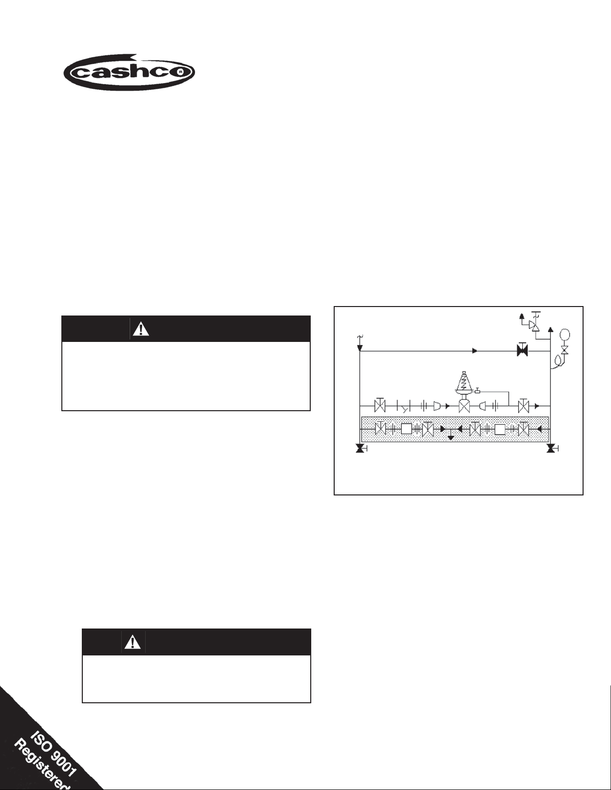
SRV
Outlet
@ P
2
P
1
Supply
@ P
1
Model 8310HP or 8310 LP
Pressure Reducing Regulator
TR
Blowdown-Drain Blowdown-Drain
(Shaded portion for steam/condensate systems)
Recommended Piping Schematic For
Pressure Reducing Station
6. Clean the piping of all foreign material including chips,
welding scale, oil, grease and dirt before in stall ing the
regulator. Strainers are rec om mend ed.
7. In placing thread sealant on pipe ends prior to en gage ment, ensure that excess material is re moved
and not allowed to enter the regulator upon start-up.
8. Flow Direction: Install so the fl ow direction match es
the arrow cast on the body. Install an external sensing
line (1/2" O.D. (DN15) tubing minimum) from the 3/8"
(DN10) NPT con nec tion in needle valve (39) to a point
down stream, pref er a bly at gauge location. If regulator pipe line is ex pand ing to a larger pipe line, always
connect sensing line to the larger pipe line.
9. For best performance, install in well drained hor i zon tal
pipe, properly trapped, if a steam service ap pli ca tion.
By pass
TR
Page 2

10. Basic Regulator - (Refer to Figure 1): Regulator may
be rotated around the pipe axis 360°. Rec om mend ed
position is with spring chamber ver ti cal upwards. Orient
such that the spring chamber vent hole does not collect
rainwater or debris.
11. Regulators are not to be direct buried un der ground.
12. For insulated piping systems, recommendation is to not
insulate regulator.
III. PRINCIPLE OF OPERATION
1. Movement occurs as pressure variations register on the
diaphragm. The registering pressure is the outlet P2,
or downstream pressure. The range spring opposes
di a phragm movement. As outlet pressure drops, the
IV. START-UP
1. Start with the block valves closed. A bypass valve may
be used to maintain outlet pressure in the down stream
system without chang ing the fol low ing steps.
CAUTION C
DO NOT HYDROSTATIC TEST THRU AN IN STALLED
UNIT; ISOLATE REGULATOR FROM TEST. The upper
range spring pressure level listed on the name plate is
the rec om mend ed “up per operative limit” for the sens ing
di a phragm (see Section IV. Start-up, Number 7.) High er
pres sures could cause internal damage. In ad di tion, note
on the name plate that the Inlet and Outlet pres sure and
tem per a ture ratings are at dif fer ent levels.
SECTION III
range spring pushes the di a phragm down, opening
the ports; as outlet pres sure increases, the di a phragm
push es up and the port opening closes.
2. A complete diaphragm failure will cause the reg u la tor
to fail open.
SECTION IV
7. Continue to slowly open the outlet (downstream) block
valve, especially when the downstream piping sys tem
isn’t pressurized. If the outlet (down stream) pressure
exceeds the de sired pres sure, close the block valve
and go to Step 2, then return to Step 4.
2. Relax the range spring by turning the adjusting screw
counter clockwise (CCW) (viewed from above) a min i mum of three (3) full revolutions. This re duc es the
outlet (downstream) pres sure set point.
3. If it is a “hot” piping system, and equipped with a bypass valve, slowly open the bypass valve to preheat
the system piping and to allow slow ex pan sion of the
piping. Ensure proper steam trap operation, if installed.
Close ly monitor outlet (down stream) pressure via gauge
to ensure not over-pres sur iz ing. NOTE: If no bypass
valve is in stalled, extra caution should be used in starting up a cold system; i.e. do everything slowly.
4. Crack open the outlet (downstream) block valve.
5. Slowly open the inlet (upstream) block valve ob serv ing
the outlet (downstream) pressure gauge. De ter mine if
the regulator is fl owing. If not, slowly rotate the regulator
adjusting screw clock wise (CW) (viewed from above)
until fl ow be gins.
6. Continue to slowly open the inlet (up stream) block valve
until fully open.
SECTION V
8. When fl ow is established steady enough that the outlet
(downstream) block valve is fully open, begin to slowly
close the bypass valve, if in stalled. NOTE: The needle
valve (39) is shipped in a full open position. If the system
is unstable due to pressure fl uctuations, slowly close
the needle valve (39) until the system becomes stable.
This needle valve (39) should never be in a fully closed
position.
9. Develop system fl ow to a level near its expected normal
rate, and reset the regulator setpoint by turning the
adjusting screw CW (viewed from above) to increase
outlet pressure, or CCW to reduce outlet pressure.
10. Reduce system fl ow to a minimum level and observe
setpoint. Outlet pressure will rise from the set point
of Step 9. The maximum rise in outlet pressure on
decreasing fl ow should not exceed the stated upper
limit of the range spring by greater than 10%; i.e. 10-40
psig (.69-2.8 Barg) range spring, at low fl ow the outlet
pressure should not exceed 44 psig (3 Barg). If it does,
consult factory.
V. SHUTDOWN
CAUTION D
1. On systems with a bypass valve, and where system
pressure is to be maintained as the reg u la tor is shut
down, slowly open the bypass valve while closing the inlet
(up stream) block valve. Fully close the inlet (up stream)
block valve. (When on bypass, the system pres sure
must be con stant ly observed and manually reg u lat ed.)
Close the outlet (downstream) block valve.
2 IOM-8310HP/LP-BASIC
Do not walk away and leave a bypassed regulator
un at tend ed!
2. If the regulator and system are to both be shut down,
slowly close the inlet (upstream) block valve. Close the
outlet (down stream) valve only if regulator re mov al is
re quired.
Page 3
VI. MAINTENANCE
WARNING 1
SYSTEM UNDER PRESSURE. Prior to performing any
main te nance, isolate the regulator from the system and
relieve all pressure. Failure to do so could result in
personal injury.
A. General:
1. Maintenance procedures hereinafter are based
upon removal of the regulator unit from the pipeline
where installed.
2. Owner should refer to owner’s pro ce dures for
re mov al, handling, cleaning and disposal of nonreuseable parts, i.e. gaskets, etc.
3. Refer to Figure 1 for standard regulator (NOTE:
“LP” variation has larger di a phragm area than “HP”
variation). Refer to Figures 2 through 4 for option
blow-ups.
B. Diaphragm Replacement:
1. Using an overhead hoist, lift regulator on to a fl at
surface work bench.
WARNING 2
SECTION VI
8. Pry loose pressure plate (22) from diaphragm(s)
(20) and remove both. In spect to ensure no de for ma tion due to over-pres sur iza tion. If de formed,
replace.
NOTES: 1. Not re mov ing the pusher plate (17) or
rotating the valve plug assembly (12) will pro vide
per for mance equal to orig i nal fac to ry per for mance
when diaphragm(s) (20) is re placed with a like
diaphragm(s) (20). Refer to Section VI.C, steps
12 and 13 for correct diaphragm setting if pusher
plate (17) or stem lock nut (19) is re moved, or valve
plug as sem bly (12) is rotated.
2. Refer to quantity of diaphragm(s) (20) in cor po rat ed in the bill of ma te ri als listing. De pend ing on
outlet pressure level, multiple metal di a phragms
may be “stacked”.
9. Remove diaphragm gasket (21) and pusher plate gasket (18). Clean gasket sealing sur fac es thor ough ly.
10. Install new diaphragm gasket (21) on di a
case (14) fl ange and new pusher plate gasket (18)
on pusher plate, if required. NOTE: No gaskets
utilized with a com po si tion (soft) di a phragm).
11. Position new diaphragm(s) (20) over threaded end
of valve plug assembly (12).
12. Ensuring that the curved outer rim side of the pressure plate (22) rests against the diaphragm(s) (20)
directly, place the pres sure plate (22) over threaded
end of the valve plug assembly (12).
phragm
SPRING UNDER COMPRESSION. Prior to re mov ing
fl ange bolts, relieve spring compression by removing
the ad just ing screw. Failure to do so may result in fl ying
parts that could cause per son al injury.
2. Relax range spring (28) by turning ad just ing screw
(or T-bar) (32) CCW (viewed from above) until
re moved from spring chamber (13).
3. Draw or embed a match mark between di a phragm
case (14) and spring chamber cast ing (13) along
fl anged area.
4. Remove all fl ange nuts (30) and bolts (29).
5. Remove spring chamber (13), spring button (27),
and range spring (28).
6. Draw second match mark on diaphragm case
(14) fl ange in alignment with a match mark on the
threaded end of the valve plug assembly (12) to
indicate “free vertical movement” position of the
valve plug assembly (12).
7. Securing the “fl ats” on the threaded end of the
valve plug assembly (12) with ad just able wrench,
re move pressure plate nut (24) by rotating CCW
(viewed from above).
NOTE: Do not rotate the valve plug assembly (12).
The plug (12.1) and seat rings (10 & 11) have been
me chan i cal ly lapped at the factory per ANSI Class
II seat leakage and assembled to pro vide op ti mum
“free vertical movement”.
13. Install pressure plate nut (24) on threaded end of
valve plug as sem bly (12) and tighten to a torque
value of 75-80 Ft-lbs (101-108 Nm) for metal di a phragm, or 30-35 Ft-lbs (40-47 Nm) for com po si tion
di a phragm. Main tain align ment of match marks on
the valve plug as sem bly (12) with second match
mark on di a phragm case (14) fl ange. NOTE: Use
two fl ange bolts (29) to keep multiple di a phragms'
(20) bolt holes prop er ly aligned while tight en ing
pres sure plate nut (24). DO NOT USE FINGERS
TO HOLD DI A PHRAGMS (20) DUR ING TIGHT EN ING OF PRES SURE PLATE NUT (24).
14. Set range spring (28) on retainer hub of pres sure
plate (22).
15. Place multi-purpose, high temperature grease into
depression of spring button (27) where ad just ing
screw (or T-bar) (32) bears. Set spring button (27)
on to range spring (28); ensure spring button (27)
is laying fl at.
16. Aligning the match marks, place spring cham ber
(13) over the above stacked parts. In stall all fl ange
bolts (29) and fl ange nuts (30). Me chan i cal ly
tight en bolting (29) (30) in a cross pattern that allows spring cham ber (13) to be pulled down evenly.
Rec om mend ed torque values are as fol lows:
Model
8310HP ALL 45 ft-lbs (61 Nm) 5/8" Ø
8310LP ALL 45 ft-lbs (61 Nm) 1/2" Ø
Diaphragm
Material
Torque
Bolt
Size
3IOM-8310HP/LP-BASIC
Page 4

NOTE: Never replace bolting (29) (30) with just
any bolting, if lost. Bolt heads and nuts are marked
with specifi cation identifi cation mark ings. Use only
proper grades as re place ments.
17. Reinstall adjusting screw (or T-bar) (32) with lock
nut (or lever) (33).
18. Spray liquid leak detector to test around bolting
(29)(30), di a phragm case (14), and spring cham ber
(13) fl ang es for leakage. Ensure that an outlet
pressure is main tained dur ing this leak test of at
least mid-range spring level; i.e. 10-40 psig (.69-2.8
Barg) range spring, 25 psig (1.7 Barg) test pressure
minimum.
C. Trim Inspection:
and in need of re place ment, contact the fac to ry
for au tho ri za tion to return unit for re pair. NOTE:
Overhaul and replacement of trim parts is not
easily ac com plished by non-factory trained
per son nel.
8. Remove the lower body gasket (6) and clean seal ing sur face thoroughly.
9. Install valve plug assembly (12) into body (1) and
place new body gasket (6) onto body (1).
10. Align match mark and replace bottom fl
ange (3) on
body (1). Reinstall fl ange stud nuts (8). Me chan i-
cal ly tighten nuts (8) in al ter nat ing cross pattern
that allows bot tom fl ange (3) to be pulled up evenly.
Rec om mend ed torques values are as follows:
1. To inspect the internal trim parts, refer to Section
VI.A. and B.1 through 9 for diaphragm re place ment
and proceed as follows.
2. Secure the “fl ats” on the threaded end of the valve
plug assembly (12) with adjustable wrench and
remove pusher plate (17) and stem lock nut (19)
by rotating CCW (viewed from above). NOTE: Do
not rotate the valve plug assembly (12).
3. Draw or embed a match mark between body (1)
and bottom fl ange (3).
4. Loosen and remove body stud nuts (8) CCW
(viewed from bottom) to remove bottom fl ange (3).
In spect the bottom guide bush ing (4) for ex ces sive
wear. If worn, both the guide bushing (4) and the
bottom fl ange (3) must be replaced. NOTE: DO
NOT RE MOVE BON NET (2). The bonnet (2) acts
as a guide to align the valve plug assembly (12)
into the seat rings (10 and 11).
5. Firmly grasp end of the valve plug assembly (12)
by hand and pull out of the body (1) cavity.
6. Inspect the seating surfaces of the plug (12.1) for
nicks or excessive wear.
7. Using a fl ashlight or other light source, ex am ine
the interior of body (1) cavity. Also, inspect the
seating surfaces of both the upper and lower seat
rings (10 and 11) for ex ces sive wear. If either the
plug (12.1) or the seat rings (10 and 11) are worn
Regulator Size Torque Bolt Size
1-1/2" - 2" (DN32-50) 50 Ft-lbs (68 Nm) 1/2"
3" - 4" (DN80-100) 100 Ft-lbs (136 Nm) 5/8"
11. Fully thread stem lock nut (19) and pusher plate (17)
on end of valve plug assembly (12). Refer to Figure
1 for correct orientation of the pusher plate (17).
12. Calibrate diaphragm (20) setting and correct valve
plug assembly (12) travel as follows:
a) Lift and hold valve plug assembly (12) up tight
against the seats (10 and 11).
b) Adjust the pusher plate (17) so that the gasket
surface face of the pusher plate (17) is fl ush with
the top of the diaphragm case (14) fl ange.
c) Draw the stem lock nut (17) up tight against
the pusher plate (17) by holding “fl ats” milled
on push er plate (17).
13. Grasp threaded end of valve plug assembly (12) by
hand and ensure that the assembly moves freely
by lifting the valve plug as sem bly (12) in and out
of the seats (10 and 11), making sure it does not
“stick”. If it does not move freely, rotate valve plug
assembly (12) CW until new position is found which
allows optimum “free vertical move ment” in and out
of seats.
14. Proceed with diaphragm (20) assembly in struc tions
in accordance with Section IV.B., steps 10 through
18. NOTE: Do not rotate valve plug as sem bly (12)
from optimum “free vertical move ment” po si tion
during fi nal as sem bly.
4 IOM-8310HP/LP-BASIC
Page 5

SECTION VII
VII. TROUBLE SHOOTING GUIDE
1. Erratic operation; chattering.
RemediesPossible Causes
A. Oversized regulator; inadequate rangeability. A1. Check actual fl ow conditions, re-size regulator for minimum and maximum
fl ow.
A2. Decrease regulator pressure drop; decrease inlet pressure by placing a
throttling orifi ce in inlet piping union; 2-stage pressure drop by using with
another regulator in series.
A3. Install next step higher range spring. Contact factory.
A4. Before replacing regulator, contact factory.
B. Worn plug/stem assembly; inadequate guiding. B1. Contact factory.
2. Leakage through the spring chamber vent hole.
Possible Causes
A. Normal-life diaphragm failure. A. Replace diaphragm.
B. Abnormal short-life diaphragm failure. B1. Can be caused by excessive chattering. See No. 1. to remedy chatter.
B2. Can be caused by corrosive action. Consider alternate diaphragm material.
B3. For composition diaphragms, assure not subjecting to over-temperature
conditions.
B4. Downstream (outlet) pressure buildup occuring that overstresses
diaphragms. Relocate regulator or protect with safety relief valve.
Remedies
3. Downstream pressure will not reach desired setting.
RemediesPossible Causes
A. Regulator undersized. A1. Confi rm by opening bypass valve together with regulator.
A2. Check actual fl ow conditions, re-size regulator; if regulator has inadequate
capacity, replace with larger unit.
B. Incorrect range spring (screwing in CW of adjust- B. Replace range spring with proper higher range. Contact factory.
ing screw does not allow bringing pressure level
up to proper level).
C. Too much droop. C1. Review droop expected.
C2. Contact factory.
D. Restricted diaphragm movement. D. Ensure no moisture in spring chamber at temperatures below freeze point.
Ensure no dust or debris entering vent opening. If rainwater or debris can
enter, re-orient spring chamber.
4. Excessive pressure downstream.
Possible Causes Remedies
A. Regulator not closing tightly. A. Inspect trim and plug alignment.
B. Downstream block. B. Check system; isolate (block) fl ow at regulator inlet - not outlet. Relocate
regulator if necessary.
C. No pressure relief protection. C. Install safety relief valve, or rupture disc.
D. Restricted diaphragm movement. D. Ensure no moisture in spring chamber at temperatures below freeze point.
Ensure no dust or debris entering vent opening. If rainwater or debris can
enter, re-orient spring chamber.
5. Sluggish operation.
A. Plugged spring chamber vent. A. Clean vent opening.
B Fluid too viscous. B. Heat fl uid. Contact factory.
RemediesPossible Causes
5IOM-8310HP/LP-BASIC
Page 6

SECTION VIII
VIII. ORDERING INFORMATION
NEW REPLACEMENT UNIT vs PARTS "KIT" FOR FIELD REPAIR
To obtain a quotation or place an order, please retrieve the Serial Number and Product Code that was stamped
on the metal name plate and attached to the unit. This information can also be found on the Bill of Material
("BOM"), a parts list that was provided when unit was originally shipped. (Serial Number typically 6 digits).
Product Code typical format as follows: (last digit is alpha character that refl ects revision level for the product).
–
NEW REPLACEMENT UNIT:
Contact your local Cashco, Inc., Sales Rep re sen ta tive with the Serial Number and Product code.
With this information they can provide a quotation
for a new unit including a complete description,
price and availability.
CAUTION
Do not attempt to alter the original construction of any
unit without assistance and approval from the factory. All
purposed changes will require a new name plate with appropriate ratings and new product code to accommodate
the recommended part(s) changes.
PARTS "KIT" for FIELD REPAIR:
Contact your local Cashco, Inc., Sales Rep re sen ta tive with the Serial Number and Product code.
Identify the parts and the quantity required to repair
the unit from the "BOM" sheet that was provided
when unit was originally shipped.
–
7
NOTE: Those part numbers that have a quantity indicated
under "Spare Parts" in column "A” refl ect minimum
parts required for inspection and rebuild, - "Soft
Goods Kit". Those in column “B” include minimum
trim replacement parts needed plus those "Soft
Goods" parts from column "A".
If the "BOM" is not available, refer to the crosssectional drawings included in this manual for part
identifi cation and selection.
A Local Sales Representative will provide quotation
for appropriate Kit Number, Price and Availability.
The contents of this publication are presented for informational purposes only, and while every effort has been made to ensure their accuracy, they are not to be
construed as warranties or guarantees, express or implied, regarding the products or services described herein or their use or applicability. We reserve the right to
modify or improve the designs or specifi cations of such product at any time without notice.
Cashco, Inc. does not assume responsibility for the selection, use or maintenance of any product. Responsibility for proper selection, use and maintenance of any
Cashco, Inc. product remains solely with the purchaser.
6 IOM-8310HP/LP-BASIC
Page 7

NOTES
7IOM-8310HP/LP-BASIC
Page 8

Item No. Description Repair Kit A
1 Body
2 Bonnet
3 Bottom Flange
4 Guide Bushing
5 Stem Bushing
6 Body Gasket ---------------------------------------‡
7 Body Stud
8 Body Stud Nut
10 Upper Seat Ring
11 Lower Seat Ring
12 Valve Plug Assembly
12.1 Plug
12.2 Stem
12.3 Pin (Groove)
13 Spring Chamber
14 Diaphragm Case
15 O-ring ------------------------------------------------‡
16 Bonnet Nut
17 Pusher Plate
18 Pusher Plate Gasket ----------------------------- ‡
19 Stem Lock Nut
20 Diaphragm(s) -------------------------------------- ‡
21 Diaphragm Gasket ------------------------------- ‡
22 Pressure Plate
23 Lower Pressure Plate
24 Pressure Plate Nut
25 Diaphragm Ring
27 Spring Button
28 Range Spring
29 Flange Bolt
30 Flange Nut
31 Nameplate
32 Adjusting Screw (or Handwheel Assy)
33 Adjusting Screw Lock nut (or Lever)
34 Seal Washer
35 Closing Cap
36 Closing Cap Gasket
37 Bleeder Valve
38 Pipe Nipple
39 Needle Valve
40 Spring
41 Diaphragm Case Nut
42 Flush Bushing
43 Pipe Plug
51 Pipe Nipple
Not Shown:
44 Pipe Nipple
45 Elbow
54 Drive Screw
55 Flow Arrow
13
32
13
22
31
‡
20
29
‡
21
17
30
19
14
16
2
4
10
6
8
7
Figure 1: Standard Model 8310HP/LP
(NOTE: Variation “LP” has a larger diaphragm area than the “HP”.)
37
42
36
35
41
33
27
28
24
18
39
38
15
7
8
6
12
1
11
4
‡
5
‡
‡
3
25
Figure 3: Model 8310HP only – Option -80, High Pressure
Spring Cham ber Construction
Cashco, Inc.
P.O. Box 6
Ellsworth, KS 67439-0006
PH (785) 472-4461
Fax. # (785) 472-3539
www.cashco.com
email: sales@cashco.com
Printed in U.S.A. IOM-8310HP/LP-Basic
Cashco GmbH
Handwerkerstrasse 15
15366 Hoppegarten, Germany
PH +49 3342 4243135
Fax. No. +49 3342 4243136
www.cashco.com
Email: germany@cashco.com
Cashco do Brasil, Ltda.
Al.Venus, 340
Indaiatuba - Sao Paulo, Brazil
PH +55 11 99677 7177
Fax. No.
www.cashco.com
Email: brazil@cashco.com
51
40 23
2
Figure 2: Model 8310HP only – Option -20, Dome Loaded
33
35
34
36
13
43
Figure 4: Model 8310HP/LP, Option-1 Closing Cap
 Loading...