

Page 1
INSTALLATION, OPERATION & MAINTENANCE MANUAL (IOM)
IOM-5381
12-13
MODEL 5381
PRESSURE REDUCING SANITARY REGULATOR
SECTION I
I. DESCRIPTION AND SCOPE
Model 5381 is a pressure reducing regulator used to control downstream (outlet or P2) pressure. Inlet and outlet
size is 1/2" (DN15) with Tri-Clamp® connections. The 5381 incorporates a stainless steel body. Refer to Tech ni cal
Bulletin 5381-TB for specifi c design conditions and selection recommendations.
SECTION II
II. INSTALLATION
CAUTION
Installation of adequate overpressure pro tec tion
is recommended to pro tect the reg u la tor and
all downstream equip ment from dam age in the
event of reg u la tor failure.
1. An inlet block valve should al ways be installed
upstream of the regulator.
2. If service application is continuous such that
shut down is not readily accomplished, it is recommended that an inlet block valve, outlet block
valve, and a manual bypass valve be installed.
CAUTION
The maximum outlet pressure is list ed on the name plate as the upper range spring pres sure level, and
is the rec om mend ed “upper operative limit” for the
sens ing diaphragm (see Sec tion IV. Startup, Step
7). Higher press ures could dam age the di a phragm.
(Field hydro static tests fre quent ly destroy dia phragms. DO NOT HYDRO STATIC TEST THRU AN
IN STALLED UNIT; ISO LATE FROM TEST.)
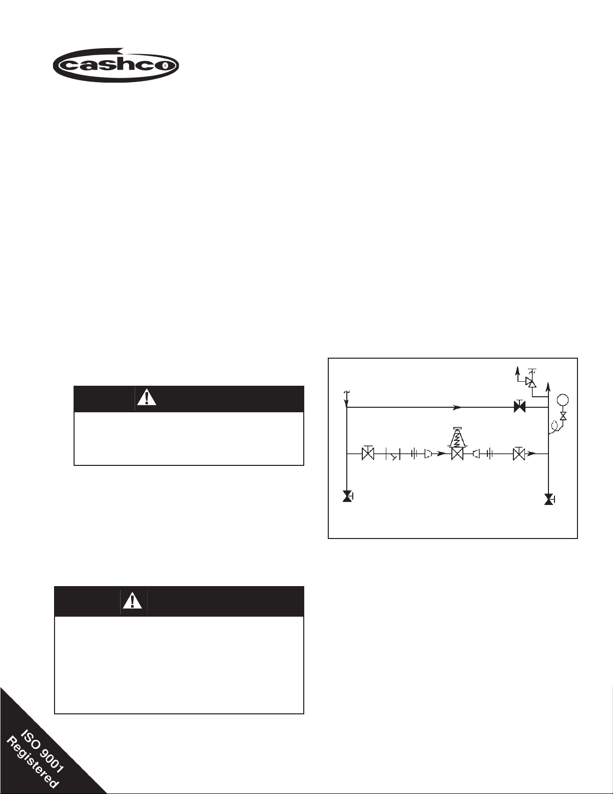
SRV
Outlet
@ P
2
P
1
Supply
@ P
1
Blowdown-Drain
Model
5381
Bypass
Blowdown-Drain
Recommended Piping Schematic
For Pressure Reducing Station
3. An outlet pressure gauge should be located ap proxi mately ten pipe diameters downstream, and with in
sight.
4. All installations should include a downstream re lief
device if the inlet pressure could exceed the pres sure
rating of any downstream equip ment or the maximum
outlet pressure rating of the unit.
5. Flow Direction: Install so the fl ow direction match es
the arrow stamped on the regulator body.
6. Install in well drained hori zon tal pipe, properly trapped
with spring chamber (2) in the vertical position to allow
for proper draining.
Page 2

SECTION III
III. PRINCIPLE OF OPERATION
1. Movement occurs as pressure variations register on the diaphragm. The registering pressure
is the outlet, P2, or downstream pressure. The
range spring op pos es diaphragm movement. As
IV. STARTUP
1. Start with the block valves closed. A bypass
valve may be used to maintain outlet pressure
in the down stream system without changing the
fol low ing steps.
2. Relax the range spring by turning the adjusting
knob (30) counter clockwise (CCW) a min i mum of
three (3) full revolutions. This re duc es the outlet
(down stream) pressure set point.
3. If it is a “hot” piping system and equipped with
a bypass valve, slowly open the bypass valve
to pre-heat the system piping and to allow slow
ex pan sion of the piping. Assure proper steam
trap operation if installed. Closely monitor outlet
(down stream) pres sure via gauge to assure not
over-pressurizing. NOTE: If no bypass valve is
in stalled, extra caution should be used in starting
up a cold system; i.e. do everything slowly.
4. Crack open the outlet (downstream) block
valve.
5. Slowly open the inlet (upstream) block valve ob serv ing the outlet (downstream) pressure gauge.
De ter mine if the regulator is fl owing. If not, slowly
rotate the regulator's adjusting knob clock wise
(CW) until fl ow begins.
outlet pressure drops, the range spring pushes
the di a phragm down, opening the port; as outlet
pres sure in creas es, the diaphragm pushes up
and the port opening closes.
2. A complete diaphragm failure will cause the reg u la tor to fail open.
SECTION IV
6. Continue to slowly open the inlet (upstream)
block valve until fully open.
7. Continue to slowly open the outlet (downstream)
block valve, especially when the downstream
pip ing system isn't pressurized. If the outlet
(down stream) pressure exceeds the desired
pres sure, close the block valve and go to Step
2, then return to Step 4.
8. When fl ow is established steady enough that the
outlet (downstream) block valve is fully open, be gin to slowly close the bypass valve if installed.
9. Develop system fl ow to a level near its expected
normal rate, and reset the regulator set point by
turning the adjusting knob CW to in crease outlet
pressure, or CCW to reduce outlet pres sure.
10. Reduce system fl ow to a minimum level and
ob serve set point. Outlet pressure will rise from
the set point of Step 9. The maximum rise in
outlet pressure on decreasing fl ow should not
exceed the stated upper limit of the range spring
by greater than 10%; i.e. 20-80 psig (1.38-5.52
Barg) range spring, at low fl ow the outlet pressure
should not exceed 88 psig (6.07 Barg), if it does,
consult factory.
V. SHUTDOWN
1. On systems with a bypass valve, and where sys tem pressure is to be maintained as the reg u la tor
is shut down, slowly open the bypass valve while
closing the inlet (up stream) block valve. Fully
close the inlet (upstream) block valve. (When on
bypass, the system pressure must be constantly
observed and manually regulated. Close the
outlet (down stream) block valve.
2
SECTION V
CAUTION
Do not walk away and leave a bypassed
regulator unattended.
2. If the regulator and system are to both be shut
down, slowly close the inlet (upstream) block
valve. Close the outlet (downstream) valve only
if reg u la tor re mov al is re quired.
IOM-5381
Page 3
SECTION VI
VI. MAINTENANCE
WARNING
SYSTEM UN DER PRES SURE. Prior to performing
any maintenance, isolate the reg u la tor from the system and relieve all pres sure. Failure to do so could
result in personal injury.
A. General:
1. Maintenance procedures here in af ter are
based upon removal of the reg u la tor unit
from the pipeline where installed.
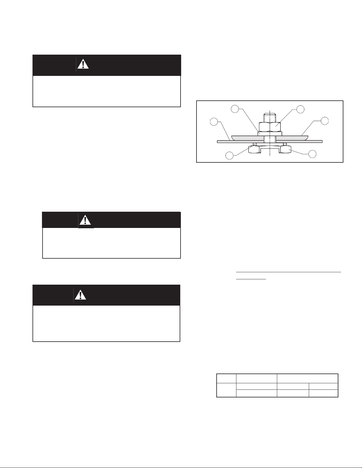
5. Remove the diaphragm subassembly
con sist ing of the pressure plate nut
(10), lock wash er (9), pres sure plate (3),
di a phragm (13), push er plate O-ring (15)
and pusher plate (4). NOTE: Refer to the
quan tity of dia phragms (13) in cor po rated
per the bill of ma te ri als listing. De pend ing
on outlet pres sure level, multiple metal
diaph ragms may be “stacked”.
9
13
10
3
2. Owner should refer to owner's pro ce dures for re mov al, handling, cleaning
and disposal of non reuseable parts, i.e.
gas kets, etc.
3. Refer to Figure 2 for basic regulator, item
number reference ( ).
B. Diaphragm Replacement:
CAUTION
To prevent damage to body, use lead jaws when
clamping body in a vise. Position body so that
vise does not close over inlet and outlet connections.
1. Securely install the body (1) in a vise with
the spring chamber (2) oriented up wards.
WARNING
SPRING UNDER COMPRESSION. Prior to re mov ing spring chamber, relieve spring com pres sion by
back ing out the adjusting knob. Failure to so so
may result in fl ying parts that could cause personal
injury.
2. Relax range spring (17) by turning adjusting knob (30) CCW until re moved from
spring cham ber (2).
15
Figure 1: Diaphragm Sub as sem bly
6. Loosen pressure plate nut (10) and
sep a rate all parts (3, 4, 9, 13 & 15) of the
diaphragm sub as sem bly.
7. Inspect pressure plate (3) to assure no
de for ma tion due to over-pressurization.
If de formed, re place.
8. Remove di a phragm gasket (14). (If a
composition di a phragm is used there is
no di a phragm gasket (14).
9. Clean inside body surfaces in ac cor dance with Owner's cleaning pro ce dures.
Do not scratch di a phragm O-ring seating surface NOTE: Maintenance must
in clude a level of clean li ness equal to
Cash co clean ing stan dard #S-1576.
Con tact fac to ry for details.
10. Reassemble diaphragm subassembly
by plac ing push er plate O-ring (15),
diaphragm(s) (13), pressure plate (3) and
lock washer (9) over the threaded post
of pusher plate (4). As sure the pres sure
plate (3) is placed with curved outer rim
down next to the di a phragm (13) surface.
Tighten pusher plate nut (4) to the fol low ing torque values:
4
IOM-5381
3. Loosen spring chamber (2) by placing
wrench on “fl ats” and rotating CCW mak-
ing sure not to use the fl at where the vent
hole is located.
4. Remove spring chamber (2), range spring
(17) and spring button (5).
Sizes Diaphragm Torque Value
Composition 15 in/lbs. (1.7 Nm)
Metal 60 in/lbs. (6.8 Nm)
ALL
11. For metal diaphragm(s) (13), place
dia phragm gas ket (14) into body re cess
(none re quired for com po si tion di a phragm). Set di a phragm sub as sem bly
into the body.
3
Page 4

12. Place the range spring (17) over the pres sure
plate nut (10) of the diaphragm subassembly.
13. Apply a small amount of process compatible
anti-seeze into de pres sion of spring but ton (5)
where ad just ing screw (8) bears. Set spring
button (5) onto range spring (17); ensure spring
button (5) is laying fl at on top of the spring.
14. Inspect body (1) and spring chamber (2)
threads for debris. NOTE: Apply a small
amount of process compatible anti-seeze to
spring cham ber (2) threads to prevent gall ing.
Ro tate the spring cham ber (2) CW by hand into
the threaded portion of the body (1) ensuring to
not cross thread. Tighten spring chamber (2) to
body (1) con nec tion to a 30–35 Ft-lbs (41–47
Nm) torque value.
15. Reinstall adjusting knob (30) with lock nut (11)
into the spring chamber (2).
16. Pressurize with air and spray liquid leak de tec tor to test around body (1) and spring cham ber
(2) for leakage. Ensure that an outlet pressure
is maintained dur ing this leak test of at least
mid-range spring level; i.e. 20-80 psig (1.4–5.5
Barg) range spring, 50 psig (3.4 Barg) test pres sure minimum.
C. Trim Replacement
CAUTION
To prevent damage to body, use soft jaws when
clamping body in a vise. Position body so that
vise does not close over inlet and outlet connections.
1. Secure body (1) in a vise with the body cap
(6) oriented up and the spring chamber (2)
directed down wards.
NOTE: When piston (15) assemblies are
used with comp seats, Cashco, Inc. does
not rec om mend attempting to remove the
comp seat. If composition seat is dam aged,
re place entire pis ton assembly.
4. Clean fl at mating surfaces of body (1) to body
cap (6) shoulder. Be careful not to scratch
either surface.
5. Clean debris from within the body (1) cavity.
Clean all parts to be reused according to
owner's procedures. NOTE: Main te nance
must in clude a level of clean li ness equal to
Cash co clean ing stan dard #S-1576. Con tact fac to ry for de tails.
6. Place the piston (16), stem fi rst, into the
body cap (6) cavity.
7. Place piston spring (7) over spring hub of the
piston (16).
8. Place o-ring (29) in body cap (6).
9. Apply a small amount of process compatible anti-seeze to the body cap (6) threads.
Thread body cap (6) into body (1). Impact
until body cap is metal to metal against body.
10. Bench test unit for suitable operation.
NOTE: Regulators are not tight shutoff de vic es. Even if pressure builds up be yond set
point, a reg u la tor may or may not develop
bubble tight shutoff. In general, tighter shut-
off can be ex pect ed with com po si tion seat.
11. Pressurize with air and spray liquid leak de tec tor to test around body cap (6) and body
(1) for leakage. Test pres sure should be a
mini mum of 100 psig (6.9 Barg) at the inlet.
2. Remove body cap (6) by rotating CCW.
Remove o-ring (29).
3. Remove piston spring (7) and piston (16).
Note: The seat and piston (16) guide are
integral parts of the body (1) cast ing. Inspect
integral seat and parts for ex ces sive wear,
espe cially at seating surfaces. Replace if
worn, nicked or de pressed. If integral seat
is nicked, use seat lapping com pound to
re move.
4
IOM-5381
Page 5

SECTION VII
VII. TROUBLE SHOOTING GUIDE
1. Erratic operation; chattering.
Possible Causes Remedies
A. Oversized regulator; inadequate rangeability. A1. Check actual fl ow conditions, re-size regulator for minimum and maximum
fl ow.
A2. Increase fl ow rate.
A3. Decrease regulator pressure drop; decrease inlet pressure by placing a
throttling orifi ce in inlet piping union.
A4. Install next step higher range spring. Contact factory.
A5. Before replacing regulator, contact factory.
B. Worn piston; inadequate guiding. B. Replace trim ( possible body replacement).
C. Weakened/broken piston spring. C. Replace piston spring. De ter mine if corrosion is causing the failure.
2. Regulator can't pass suffi cient fl ow.
RemediesPossible Causes
A. Regulator undersized. A1. Confi rm by opening bypass valve together with regulator.
A2. Check actual fl ow conditions, re-size regulator; if regulator has inadequate
capacity, consult factory.
B. Incorrect range spring (screwing in CW of adjust- B. Replace range spring with proper higher range. Contact factory.
ing screw does not allow bringing pressure level
up to proper level).
C. Too much droop. C1. Review droop expected.
C2. Contact factory.
3. Leakage through the spring chamber vent hole.
RemediesPossible Causes
A. Normal-life diaphragm failure. A. Replace diaphragm.
B. Abnormal short-life diaphragm failure. B1. Can be caused by excessive chattering. See No. 1. to remedy chatter.
B2. Can be caused by corrosive action. Consider alternate diaphragm material.
B3. For composition diaphragms, assure not subjecting to over-temperature
conditions.
B4. Downstream (outlet) pressure buildup occurring that overstresses
diaphragms. Relocate regulator or protect with safety relief valve.
C. O-ring failure. C. Replace O-ring (15), apply appropriate torque.
4. Sluggish operation.
RemediesPossible Causes
A. Fluid too viscous. A. Heat fl uid. Contact factory.
5. Excessive pressure downstream.
Possible Causes Remedies
A. Regulator not closing tightly. A. Inspect the seating. Clean and lap metal seat surfaces; replace if lapping
does not remedy. If composition seats are depressed, nicked or embedded
with debris, replace trim.
B. Downstream block. B. Check system; isolate (block) fl ow at regulator inlet - not outlet. Relocate
regulator if necessary.
C. No pressure relief protection. C. Install safety relief valve, or rupture disc.
D. Restricted diaphragm movement. D. Assure no moisture in spring chamber at temperatures below freeze point.
Assure no dust or debris entering vent opening. If rainwater or debris can
enter, re-orient regulator.
IOM-5381
5
Page 6

SECTION VIII
VIII. ORDERING INFORMATION
NEW REPLACEMENT UNIT vs PARTS "KIT" FOR FIELD REPAIR
To obtain a quotation or place an order, please retrieve the Serial Number and Product Code that was stamped
on the metal name plate and attached to the unit. This information can also be found on the Bill of Material
("BOM") a parts list that was provided when unit was originally shipped. (Serial Number typically 6 digits).
Product Code typical format as follows: (last digit is alpha character that refl ects revision level for the product).
–
NEW REPLACEMENT UNIT:
Contact your local Cashco, Inc., Sales Rep re sen ta tive with the Serial Number and Product code.
With this information they can provide a quotation
for a new unit including a complete description,
price and availability.
CAUTION
Do not attempt to alter the original construction
of any unit without assistance and approval from
the factory. All purposed changes will require a
new name plate with appropriate ratings and new
product code to accommodate the recommended
part(s) changes.
PARTS "KIT" for FIELD REPAIR:
Contact your local Cashco, Inc., Sales Rep re sen ta tive with the Serial Number and Product code.
Identify the parts and the quantity required to repair
the unit from the "BOM" sheet that was provided
when unit was originally shipped.
–
7
NOTE: Those part numbers that have a quantity indicated
under "Spare Parts" in column "A” refl ect minimum
parts required for inspection and rebuild, - "Soft
Goods Kit". Those in column “B” include minimum
trim replacement parts needed plus those "Soft
Goods" parts from column "A".
If the "BOM" is not available, refer to the crosssectional drawings included in this manual for part
identifi cation and selection.
A Local Sales Representative will provide quotation
for appropriate Kit Number, Price and Availability.
The contents of this publication are presented for informational purposes only, and while every effort has been made to ensure their accuracy, they are not to be
construed as warranties or guarantees, express or implied, regarding the products or services described herein or their use or applicability. We reserve the right to
modify or improve the designs or specifi cations of such product at any time without notice.
Cashco, Inc. does not assume responsibility for the selection, use or maintenance of any product. Responsibility for proper selection, use and maintenance of any
Cashco, Inc. product remains solely with the purchaser.
6
IOM-5381
Page 7

NOTES
IOM-5381
7
Page 8

Figure 2: Basic Model 5381, Metal Seat Design
Item No. Description Repair Kit B
1 Body
2 Spring Chamber
3 Pressure Plate
4 Pusher Plate
5 Spring Button
6 Body Cap
8 Adjusting Screw
9 Lock Washer
10 Pressure Plate Nut
Cashco, Inc.
P.O. Box 6
Ellsworth, KS 67439-0006
PH (785) 472-4461
Fax. # (785) 472-3539
www.cashco.com
email: sales@cashco.com
Printed in U.S.A. IOM-5381
7 Piston Spring -----------------------
Cashco GmbH
Handwerkerstrasse 15
15366 Hoppegarten, Germany
PH +49 3342 4243135
Fax. No. +49 3342 4243136
www.cashco.com
Email: germany@cashco.com
Cashco do Brasil, Ltda.
Al.Venus, 340
Indaiatuba - Sao Paulo, Brazil
PH +55 11 99677 7177
Fax. No.
www.cashco.com
Email: brazil@cashco.com
Item No. Description Repair Kit B
11 Adjusting Screw Locknut
13 Diaphragm(s) -----------------------
14 Diaphragm Gasket ----------------
15 Pusher Plate O-ring----------------
16 Piston & Piston Subassy. --------
‡‡
17 Range Spring
29 Body Cap O-ring --------------------
‡‡
‡‡
‡‡
‡‡
‡‡
30 Adjusting Knob
‡‡ Recommended Spare Part
 Loading...