

Page 1

INSTALLATION, OPERATION AND MAINTENANCE MANUAL (IOM)
Model 5100 Pilot Operated
Pressure / Vacuum Relief Vent
I. DESCRIPTION AND SCOPE
IOM-5100
09-09
end-of-line
SECTION I
The maintenance of this Pilot Operated Vent Valve
(POVV) should only be done by quali ed valve
technicians. It is important that the technician be
familiar with the API and corporate standards,
corporate safety policies and the relief vent
manufacturer requirements. When repair services
are performed by an outside company, the company
needs to be a Cashco factory authorized repair
center which specializes in low pressure venting
devices.
II. VALVE DESIGN AND FUNCTION
The Model 5100 Pilot Operated Vents are used on
liquid storage tanks and other process vessels or
systems to prevent structural damage during the
process of lling or emptying of a tank or for changes
in atmospheric conditions. Excess pressure is
vented to atmosphere..
Storage tanks are pressurized when liquid is
pumped in, compressing the existing vapor or
when increasing temperature causes increased
evaporation or expansion of existing vapor.
Conversely, a vacuum may be created when uid
is pumped out or as atmospheric temperature
decreases. To prevent structural damage, vapor
must be allowed to escape or enter the tank at a
speci ed ow rate. The volume rate of venting is
dependent on the tank size, displacement rate and
the ash point of the uid. See API Standard 2000
for procedures to determine venting requirements.
For information on repair centers in your area, please
contact:
Valve Concepts, Inc.
%Cashco, Inc.
607 West 15
Ellsworth, KS 67439-0006
(785) 472-4461 (Phone)
(785) 472-3539 (Fax)
SECTION II
th
Street
Thus the vent valve is capable of operating at
pressures closer to the maximum allowable
working pressure of the tank. Operating at higher
pressures reduces evaporation and total venting
volume, thereby reducing product loss and the cost
of handling emissions.
Each application must be reviewed to ensure material compatibility with all metal and soft good
components with the service conditions. The pallet
assembly, wetted components and tubing are 316
SST. Diaphragm material is FKM, unless speci cied otherwise.
The pilot valve is factory set to comply with the
speci cations on the purchase order. The adjustable pressure range is a function of the installed
spring and will be stamped on the metal nameplate.
The set point pressure maybe changed within the
design parameters of the spring while installed on
line or in a maintenance shop. See Section IX
for setting and testing procedures.
A pilot operated relief vent has two principal
advantages over other relief vent designs:
1. Bubble tight shutoff up to 100% of set point.
2. Full open capacity for pressure relief is achieved
within 10% above set point.
This manual is intended to provide recommended
procedures and practices for installation, operation
and maintenance of the Model 5100 POVV. Although this manual cannot cover all possible contingencies, these guidelines will provide safe and
reliable pilot valve performance.
Page 2
III. SAFETY WARNINGS:
SECTION III
WARNING
Warning: Before beginning any relief vent inspection
or maintenance, carefully read and understand the
information in this manual. If there are any questions
concerning the information in this manual, please
contact the factory or an authorized repair center
before proceeding.
Tank or system protection is the primary function of
the Pilot Operated Vent Valve (POVV). It must be
selected to meet the total pressure ow requirements
within the maximum allowable working pressure
of the system on which it is installed. Consult API
Standard 2000 for tank protection sizing procedures.
Improperly speci ed relief vents may result in
structural damage to the tank or system, and can
cause severe personal injury or death.
In the event of a diaphragm failure, the Model 5100
will vent pressure to the atmosphere causing the
pressure relief valve to fail in the OPEN position.
The vent will now function like a weight loaded vent
under this condition with a lower set point. Consult
the factory for any questions related to this overpressure condition.
CAUTION
DO NOT attempt to change pressure set point beyond
the limit speci ed on the nameplate..
The 1/2” OD SST pilot valve sensing line must be
kept open and unobstructed to ensure that the pilot
“senses” the actual tank pressure. For applications
where tank vapors may condense or polymerize in
the sensing tubing or the pilot valve, a nitrogen purge
may be required to prevent internal obstruction of the
tube. Consult the factory for recommendations.
CAUTION
DO NOT attempt to remove the vent from the tank or
process vessel without rst bleeding all pressure from
the system. ALTERNATIVE MEANS OF PRESSURE
RELIEF MUST BE PROVIDED WHEN THE VENT IS OUT
OF SERVICE.
After isolating the relief vent, bleed all pressure
from both main and pilot valve before removing the
Model 5100 POVV.
NOTE: Both the pilot valve and main valve are
exposed to the process vapors. Observe all
plant procedures and Material Safety Data Sheet
recommendations before inspecting, adjusting or
servicing any components.
The vent on the spring bonnet of the pilot must
be clean and unobstructed for proper and safe
operation of the valve.
SECTION IV
IV. SHIPPING, INSPECTION AND
STORAGE:
The POVV vent is carefully packaged to prevent
damage or contamination during shipping. Inspect
the equipment when it is received and report any
damage to the carrier immediately. The POVV
should be stored in a clean environment with all
the protective ange covers in place to prevent
intrusion of foreign materials. If there are indications
of physical damage or internal contamination, the
valve may need to be disassembled, cleaned and
inspected prior to installation.
2
Lifting lugs may be provided on the main valve for
lifting and handling. To avoid damage to the lower
ange surface, rest the vent on a soft clean gasket
material until it is ready to be installed. DO NOT
store the POVV directly on the ground.
Make sure that any loading weights that might have
been shipped separately, to protect the vent during
shipping, are accounted for and stored with the vent.
These weights when required, will be installed during
installation,at installation.
IOM-5100
Page 3
V. INSTALLATION:
SECTION V
The Model 5100 POVV is a precision device that
must be handled carefully to ensure seat tightness.
WARNING
The vent must be installed in a vertical position. The
tank nozzle on which the vent is mounted should have
the same nominal diameter as the venting device. It
is recommended that the tank nozzle ange face be
within 1 degree of horizontal for best performance of
the venting device.
1. At installation, the POVV should be carefully
lifted into position using the lifting lugs on the
body. Use the case assembly (32,33) to help
align the body directly over the tank nozzle.
DO NOT use the pilot valve or pickup line to
pull the POVV into position.
2. Aluminum body vents should be mated to
at-faced 125# ASME anges. Mating anges
should be at within 0.020” and clean; free
of scratches, corrosion and tool marks. A full
faced gasket is recommended.
4. Center the gasket within the bolt circle of the
tank nozzle ange.
5. Lubricate all studs and nuts with an appropri ate thread lubricant. If stainless steel studs
and nuts are required, use an anti-seize lubri cant such as moly-disul de.
6. Remove ange protective covers and carefuly
set the POVV down on the gasket and face of
the nozzle ange.
WARNING
Minimum clearance between tank roof and vacuum
inlet port must be at least equal to the vents’ nominal ange bore. Tank nozzle bore must be greater
than or equal to vent inlet ange bore. Inlet piping
loads must be supported by appropriate structural
supports, NOT by the vent body.
7. Install lockwashers and nuts. Tighten nuts
to half the recommended torque value using
an alternating crossing pattern. See Table 2.
3. Install the ange gasket on the nozzel face.
Use either a full faced or ring gasket for
raised face anges. Ensure that the gasket
material is suitable for the service. See Table
1 for gasket dimensions.
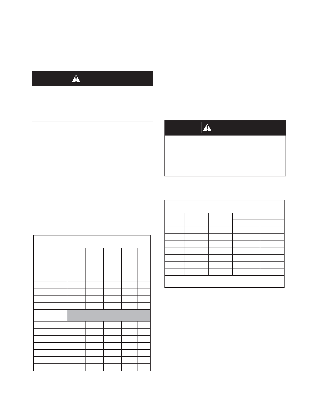
Table 1
Body Flange Gasket Dimensions
CS, SST
150# ASME RF
2’ 4.12 2.38 -- -- --
3” 5.38 3.50 -- -- --
4” 6.88 4.50 -- -- --
6” 8.75 6.62 -- -- --
8” 11.00 8.62 -- -- --
10” 13.38 10.80 -- -- --
12” 16.12 12.80 -- -- --
Alum w/ 125#
ASME FF
2” 6.00 2.00 4.75 .75 4
3” 7.50 3.00 6.00 .75 4
4” 9.00 4.00 7.50 .75 8
6” 11.00 6.00 9.50 .88 8
8” 13.50 8.00 11.75 .88 8
10” 16.00 10.0 14.25 1.00 12
12” 19.00 12.00 17.00 1.00 12
O.D. I.D. B.C. Hole Qty
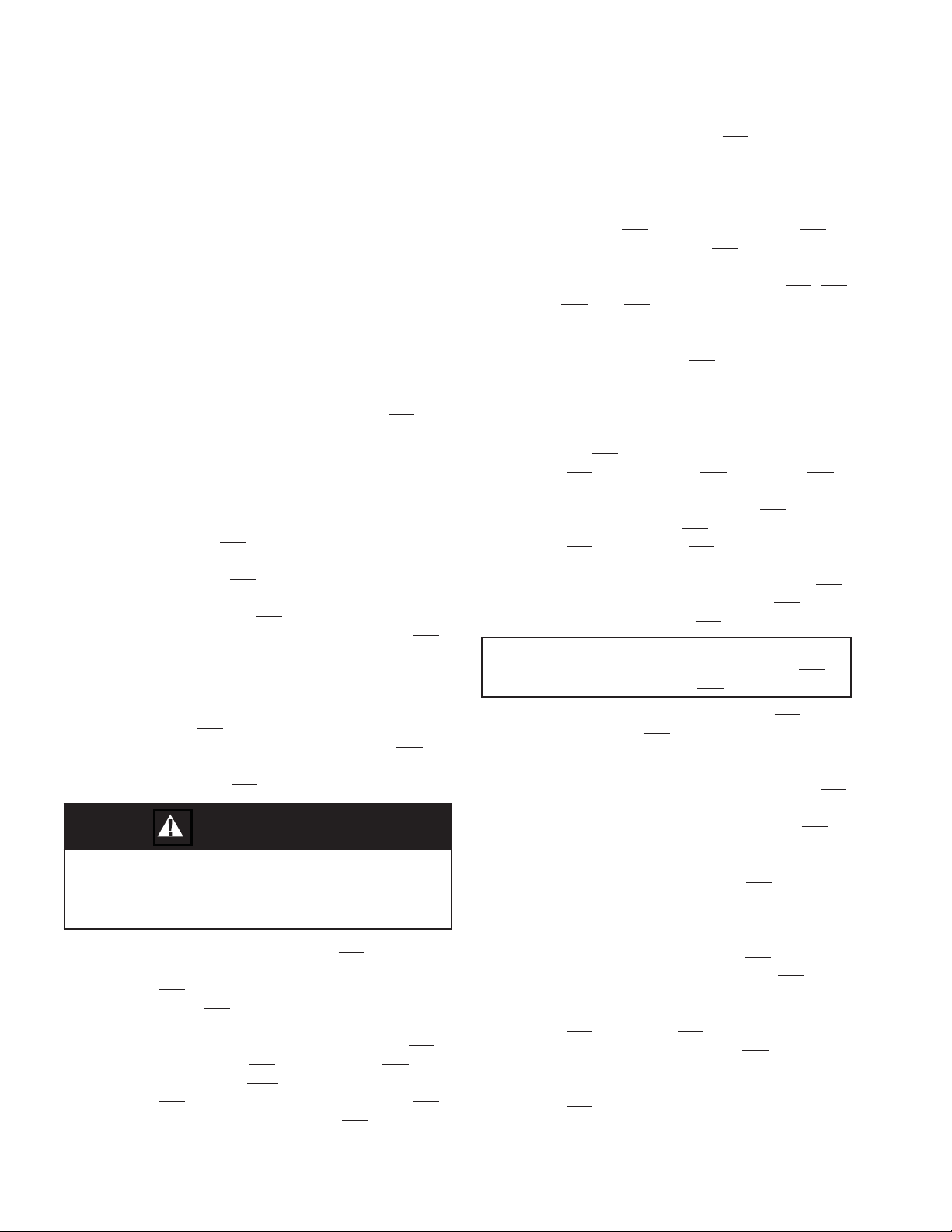
Table 2
Recommended Minimum Torque Values *
Size
2” 4 5/8”-11 31 81
3” 4 5/8”-11 43 106
4” 8 5/8”-11 29 68
6” 8 3/4’10 51 101
8” 8 3/4”-10 78 142
10” 12 7/8”-9 75 138
12” 12 7/8”-9 93 179
* Torque vlaues are based on a gasket factor m = 3.5,
gasket factor y = 4000 psi, operating pressure = 30 psi
Qty
Holes
Bolt
(UNC)
Torque (lb-ft)
Raised Face Flat Face
8. Make sure that the gasket is compressed
evenly and the anges are not distorted.
NOTE: Misalignment of ange faces will cause
bending stresses at the ange and may damage
ange joint.
9. Finish tightening nuts to the point that no ad ditional rotation occurs.
10. If loading weights were shipped separate from
the vent, install weights on vacuum pressure
pallet. Ensure that all packing has been re
moved.
IOM-5100
3
Page 4
SECTION VI
VI. PILOT MAINTENANCE:
A. General:
1. Maintenance procedures herein after are
based upon removal of the pilot/vent valve
unit from the vessel/piping where installed.
2. Owner should refer to owner’s procedures for
re mov al, handling and cleaning of non re us able parts; i.e. gaskets, suitable solvents,
etc.
3. All indicated Item Numbers that are with
respect to the Pilot Assembly will be in
pa ren the sis and un der scored; i.e. (205). All
Item Numbers that are with respect to the
Vent Valve are not un der scored; i.e. (6).
B. Separation from Main Valve and Disassembly:
1. Disconnect sense tube (57) from ttings
(48) and (244). Remove the pilot valve assembly from the nipple (53) by rotating the
pilot body (201) CCW.
2. Secure body (201) in vise with ‘sensing”
port facing front. Disconnect tubing (243)
from connectors (232),(234).
3. Paint or embed a match mark between
upper case (202), spacer (245) and lower
case (203) along anged area. NOTE lo-
cation of 1/8” NPT tap from elbow (234) in
relation to body sensing port and straight
connector (232).
WARNING
SPRING UNDER COMPRESSION. Prior to re mov ing
ange bolts, relieve spring com pres sion by backing
out the adjusting screw. Failure to do so may result
in ying parts that could cause personal injury.
4. Rotate the closing cap (205) CCW for
removal. Loosen the adjusting screw nut
(214) two revolutions. Rotate Adjusting
screw (213) CCW and remove.
5. Remove diaphragm case nuts (209),
lockwashers (210), at washers (221) and
cap screws (220). Grasp spring bonnet
(204) and lift up until diaphragm case (202)
clears top of spring button (212).
6. Secure spring bonnet (204) in a vice with
the upper diaphragm case (202) orientated
upwards.
7. Use 5/32” allen wrench to remove cap
screws (237) and lock washers (239) to
separate the bonnet (204) from the upper
case (202). Replace bonnet gasket (222)
and reassemble item numbers (202, 204,
237 and 239). Remove bonnet from vice
and set assembly aside.
8. Lift range spring (215) and spring button
(212), up and set aside.
9. Grasp the at surfaces of wrench washers
(228) with a wrench and rotate piston stud
nut (235) CCW to remove nut, lock washer
(241), spring guide (211), washers (228).
10. Remove pressure ring (250), upper
pressure plate (246), upper diaphragm
(207) and spacer (245).
11. Remove upper diaphragm washer (219),
upper diaphragm gasket (226), and
diaphragm spacer (247).
For Intermediate & High Pressure Pilots Only:
Remove diaphragm case gasket (255)
and pressure ring (251).
12. Remove lower pressure plate (206), lower
diaphragm (207), lower diaphragm washer
(219) and lower diaphragm gasket (226).
13. Rotate 7/16” hex head cap screws (238)
CCW and remove lock washers (240).
Lift up on lower diaphragm case (203) to
remove. NOTE the alignment of the four
bolt holes and the sense hole in case (203)
with the holes in the body (201).
14. Grasp the cylinder (227) / piston (208)
assembly and lift upwards to extract this
assembly from the body (201). Remove
upper and lower body gaskets (225).
15. From top of assembly, press piston stud
(230) / piston (208) downward through
the center of the cylinder (227) to remove.
Apply Dow Corning 111 lubricant in o-ring
grooves and install new piston O-rings
(224).
4
IOM-5100
Page 5

16. From opposite end of assembly use 1/8”
allen wrench to remove retaining screw
(229) and piston cap (223). Remove and
replace with new seat O-ring (233).
17. Rotate blowndown needle jam nut
(236) CCW two rotations and remove
blowndown needle (217) from body (201).
Replace with new O-ring (218).
C. Re-assembly:
1. Install piston cap (223) and retaining
screw (229) into piston (208).
2. Lightly coat cylinder (227) bore with Dow
Corning Molykote 22 lubricant and insert
piston (208) through lower opening of the
cylinder (227) and press into place.
3. Position new body gasket (225) on top of
pilot body, align gasket holes and slide
piston (208) / cylinder (227) assembly
into the body (201). DO NOT COVER
SENSING HOLE.
4. Position another body gasket (225) on top
of cylinder ange. Align holes in the lower
diaphragm case (203) with the cylinder
and body. DO NOT COVER SENSING
HOLE. Use lock washers (240) and cap
screws (238) to secure lower diaphragm
case (203) tight to the body. (201).
5. Install new lower diaphragm gasket (226)
and one diaphragm washer (219) on
piston stud (230).
6. Place a new diaphragm (207) and the
lower pressure plate (206) on piston stud.
For Intermediate & High Pressure Pilots Only:
Install diaphragm case gasket (255) and
pressure ring (251).
7. Install diaphragm spacer (247), a new
upper diaphragm gasket (226) and
diaphragm washer (219) on psiton stud
(230).
8. Place the large spacer (245) above the
diaphragm and align match marks per
previous B 3.
9. Install another new diaphragm (207) on
piston stud (230) and align the bolt holes
with parts of previous Steps 6 and 7.
10. Stack the upper pressure plate (246), the
wrench washers (228), the spring guide
(211) and piston stud lock washer (242)
over the piston stud (230).
11. Install and tighten piston stud nut (235) to
secure all parts. (Check alignment of the
bolt holes around the circumference.)
12. Position the range spring (215) and spring
button (212) on the spring guide (211).
13. Place diaphragm pressure ring (250) on
top of diaphragm (207).
14. Lower the upper diaphragm case (202) /
spring bonnet (204) assembly over the
spring (215), allow to rest on the diaphragm
pressure ring (250). (Ensure alignment of
match marks per prervious B 3.)
15. Install diaphragm case screws (220), at
washers (221), lock washers (210) and
nuts (209) and tighten.
16 Apply a light coat of Bostik Never-Seez
to threads of blowndown needle (217).
Thread completely into body until the nut
(236) contacts the body (201) and then
back our two rotations. Rotate nut (236)
CW to secure nut tight.
17. Reinstall adjusting screw (213) and jam
nut (214) in spring bonnet (204).
18. Refer to Section IX for Calibration and
Testing
19. Install pilot body assembly on nipple (53)
tight with CW rotation. Ensure straight
connector (244) of the pilot valve assembly
is directly above sensing tube connector
(48) of the main valve assembly.
20. Reconnect tubing (243) to ttings (232),
(234) and tubing (57) to ttings (48),(244).
IOM-5100
5
Page 6

VII. VENT VALVE MAINTENANCE:
CAUTION
SECTION VII
Actuator Diaphragm Replacement:
a. Paint or embed a match mark between
upper case (33) and lower case (32) along
anged area.
If the vent valve must be removed from the tank for
any reason, make sure that all pressure has been released before the ange fasteners are loosened. Refer
to your company procedures before venting the tank
pressure and when handling toxic or otherwise hazardous materials. Observe all standard safety precautions as speci ed on Material Safety Data Sheets for
the product(s) in the system while removing the valve
and during the repair.
A. General:
1. The Model 5100 POVV does not require
routine lubrication or adjustments. It
should be checked periodically, at least
twice a year, to con rm that the vent is
functioning properly and that the set point
is correct.
2. The pilot valve is designed to function in a
failsafe manner. The failure of a seal or a
diaphragm will cause pressure to be vented to the atmosphere; the resulting loss in
pressure will cause the main valve to open
under rising pressure.
b. Loosen and remove nuts (35), lock
washer (37), at washer (36) and cap screw
(34).
c. Lift up and remove the upper case (33)
assemby and set aside.
d. Remove diaphragm (41) and replace
with new diaphragm. Position and align bolt
holes in the circumference of the diaphragm
with the holes in the lower case (32).
e. Reposition upper case assy (33) on dia-
phragm (41). Align marks of a. above.
f. Install cap screws (34), at washer (36),
lock washer (37) and nuts (35) and tighten.
g. Install pilot body assembly on nipple (53)
tight with CW rotation. Ensure straight connector (244) of the pilot valve assembly is
directly above sensing tube connector (48)
of the main valve assembly.
3. Periodic inspection for seat tightness
should be done to ensure compliance with
local air pollution control requirements. If
the vent relieves to the atmosphere, this
maybe accomplished with a gas detector
calibrated for the principle product in the
system.
4. The vent valve will need to be removed
from the tank for inspection of diaphragms,
gaskets and seals. When this is done, the
vent must be handled carefully using the
lifting lugs and the body.
5. The main and pilot valve housings, bodies,
pallet assemblies and other components
are exposed to the process vapor.
B. Disassembly:
1. Disconnect the tubing connections (pilot to
main Valve) (48, 57 and 244) and remove
the pilot by rotating the pilot body (201) assembly CCW from nipple (53).
h. Reconnect tubing (57) to ttings
(48),(244). Refer to Section IX for Calibration and Testing.
Pressure Pallet Diaphragm Replacement:
a. Paint or embed a match mark between
weatherhood (17) and body (1) along anged
area.
b. Rotate jam nuts (55) CCW coming to
rest against top of jack screw (7). Rotate
jack nuts (54) CCW coming to rest against
nuts (55).
c. Rotate jack screw (7) CCW and remove
from threaded end of pallet guides (16).
d. Grasp the case assy (AA) (32/33) and lift
straight up to remove (AA) and weatherhood
assy (17) from pallet guides (16).
CAUTION
Do not grasp weatherhood around the bottom edge,
it maybe sharp.
6
IOM-5100
Page 7

NOTE: Support plate (40) and pressure pal-
let stem(10) assembly will also lift out of
the body (1). (continue with step i. unless
changing gasket (49)).
p. Push cotter pin (61) into hole in stem
(10) and secure. Remove pallet (4) assembly from vise.(continue with step t. unless
changing gasket (13)).
To Remove Adapter Gasket: steps (e - h).
e. Lay the (AA) and weatherhood assy on
at surface.
f. Paint or embed a match mark between
weatherhood (17) and lower case adapter
assy (32).
g. Loosen and remove adapter bolts (38)
and washers (39). Set weatherhood (17)
to the side and remove pressure plate (29).
Remove and replace adapter gasket (49).
h. Align bolt holes in pressure plate (29)
and weatherhood (17) with lower case
adapter assy (32) and install lock washers
(39) and adapter bolts (38). Tighten securely.
i. Remove cylinder of wire screen (27) .
Inspect seating surface of seat ring (3).
j. Straighten the bent ends of cotter pin
(62) and remove pin from support plate
(40). Slide pallet(4) assembly out of tube
end.
k. Carefully secure stem (10) in a vise,
oriented such that the pallet (4) assembly
is directed upwards.
l. Remove cotter pin (61), nut (23), lock
washer (19), washer (24), diaphragm retainer plate (6), diaphragm (5) and pallet
(4) from stem (10).
m. Re-install pallet (4) on stem (10).
NOTE: Apply small amount of TFE paste
around the center opening (top surface) of
the pallet (4).
To Remove Seat Ring/Gasket: steps (q - s).
q. Place a wrench on the milled ats of
the pallet guides (16), rotate CCW to remove the guides (16) and stud spacers
(69). Mark the location of guides on the
seat ring (3) for reference at re-assembly.
r. Remove four socket head cap screrws
(11) and lift out the seat ring (3). Remove
seat gasket (13) and clean sealing surface.
s. Apply TFE paste to both sides of new
gasket and install in body(1). Position
seat ring (3) on gasket (13) and install cap
screws (11), guides (16) and stud spacers
(69). Tighten cap screws (11) and supports (16) to 15 ft. lbs.
t. Reposition cylinder of wire screen (27)
around top surface of seat ring (3).
u. Install stem (10)/pallet (4) assembly in
the tube end of support plate (40). Align
the drilled holes and insert cotter pin (62).
Bend prongs of pin around the stem to secure it in place.
v. Grasp the case assembly (AA) (32/33)
and install on pallet guides (16). Ensure
alignment of weatherhood (17) and body
(1) per step a. above.
w. Install jack screw (7) on threaded end
of pallet guides and tighten securely. Rotate jack nut (54) CW in equal increments
until they rest tight against lower case (32)
x. Rotate jam nut (55) CW to secure tight
to jack nut (54).
n. Place a new diaphragm (5) on the pal-
o. Install the diaphragm retainer plate (6),
IOM-5100
let (4). NOTE: Apply small amount of TFE
paste around the center opening (top surface) of the diaphragm (5).
washer (24), lock washer (19) and nut (23).
Secure nut tight to lock washer (19).
y. Install pilot body assembly on nipple
(53) tight with CW rotation. Ensure straight
connector (244) of the pilot valve assembly
is directly above sensing tube connector
(48) of the main valve assembly.
z. Reconnect tubing (243) to ttings
(232), (234) and tubing (57) to ttings
(48),(244).
7
Page 8

Vacuum Pallet Diaphragm Replacement:
a. Remove cover bolts (22), cover as-
sembly (2) and cover gasket (12). Inspect
cover for corrosion, damage or product
build up. Clean with a suitable solvent.
NOTE: During re-assembly, install new
cover gasket (12) (5/32-inch dia. Gortex
rope joint sealant).
b. Lift upwards to remove vacuum pal-
let (9) assembly, including any loading
weights (18) that may be resting on the
CAUTION
DO NOT change pressure ratings by removing or adding additional weights to the pallet assembly without
consulting the factory or your VCI representative.
pallet(4).
c. Place stem (9) in a vise with the
threaded end up. Remove cotter pin (61),
nut (23), lock-washer (19) and washer
(24). Lift up to remove diaphragm plate
(6) and diaphragm (5) NOTE: Apply TFE
paste to threads of the stem and around
the hole on the pallet (4).
c. Apply TFE paste to both sides of new
gaskets and install in body (1).
d. Re-assemble vacuum vent side
in reverse order, making sure that the
vacuum pallet and loading weights are in
their proper location. Tighten bolts (11),
guides (8) and spacers (69) to 15 ft. lbs.
e. Install cover gasket (12). When
installing the cover (2) ensure the vacuum
stem (9) is inserted in the stem guide in the
cover (2).
To Remove Inlet Screen:
a. Rotate bolts (15) CCW and remove.
Inspect and clean screen (14) and reinstall
to body (1).
d. Install new diaphragm (5). Re-install
washer (24), lock-washer (19) and tighten
nut (23) on stem. Insert cotter pin (61)
through hole in stem and secure.
e. Inspect and clean seat ring (3). Check
seat surface for any nicks, corrosion, pitting or product build-up. Seat surface must
be clean and smooth for vent to preform
properly.
To Remove Seat Ring/Gasket:
a. Rotate bolts (11) CCW and remove.
Remove guides (8) and spacers (69) (Use the slot on top of guides and rotate
CCW.) Mark the location of these items
on the seat ring (3) for reference at reassembly.
b. Lift up to remove seat ring (3) and
gasket (13). Inspect guides (8) and inside
of the body cavity (1) for any corrosion or
product build up. Clean as necessary.
8
IOM-5100
Page 9

SECTION VIII
VIII. ORDERING INFORMATION:
NEW REPLACEMENT UNIT vs PARTS "KIT" FOR FIELD REPAIR
To obtain a quotation or place an order, please retrieve the Serial Number and Product Code that was
stamped on the metal name plate and attached to the unit. This information can also be found on the Bill of
Material (parts list) that was provided when unit was originally shipped.) (Serial Number typically 6 digits).
NEW REPLACEMENT UNIT:
Contact your local Cashco, Inc., Sales Rep re sen ta tive with the Serial Number and Product code. With
this information they can provide a quotation for a
new unit including a complete description, price
and availability.
CAUTION
Do not attempt to alter the original construction of any
unit without assistance and approval from the factory.
All purposed changes will require a new name plate with
appropriate ratings and new product code to accomodate the recommended part(s) changes.
PARTS "KIT" for FIELD REPAIR:
Contact your local Cashco, Inc., Sales Rep re sen ta tive with the Serial Number and Product
code. Identify the parts and the quantity
required to repair the unit from the Bill of Materials sheet that was provided when unit was
originally shipped.
If the "BOM" is not available, refer to the crosssectional drawings included in this manual for
part identi cation and selection.
Local Sales Representative will provide quotation for appropriate Kit Number, Price and
Availability.
IOM-5100
9
Page 10

SECTION IX
IX. PRESSURE CALIBRATION AND
TESTING PROCEDURE FOR PILOT:
1. To determine set pressure, slowly increase
the pilot inlet pressure. Simulated actuator
pressure will rise with inlet. As set pressure
is approached, the actuator pressure will begin to decrease. Continue to increase the
inlet pressure slowly until the actuator pressure is 90% (+/- 10%) of the inlet pressure.
This is the set pressure.
2. Rotate the set pressure adjusting screw
(213) CW to increase set pressure or CCW
to decrease set pressure. Continue to rotate
the adjusting screw and repeat the test per
Step 1 previous until the speci ed set pressure is achieved.
3. To determine reseat pressure, slowly decrease the inlet pressure and the actuator
pressure will begin to increase. Reseat occurs when the actuator pressure equal the
inlet pressure.
4. The difference between set and reseat
pressure,”blowdown”, can be adjusted with
the blowdown needle (217). Maximum
clockwise rotation provides rapid relief valve
opening, “snap action”’ and maximum blowdown. Standard blowdown, unless otherwise speci ed is 7 - 10% below set pressure.
7. A small interaction occurs between set
pressure and blowdown adjustments. Readjustment of both may be required until
the speci ed set pressure and blowdown
are achieved. After completion, lock both
screws and locknuts and replace closing cap
(205) on adjusting screw (213).
8. Hold the valve at the set pressure while
preforming a soap bubble test of all bolted,
anged and threaded connections.
9. Refer to Table 3 for standard setting Speci cations.
SETTING SPECIFICATIONS - PILOT VALVE
Pilot Action
Snap 2” - 8” WC +/- 0.2”WC 75 90 +/- 3
Snap
Snap
Modulating 2” - 8” WC +/- 0.2” WC 75 100
Modulating
Modulating
Set
Pressure
8.1” WC -
1.0 psig
1.1 - 15.0
psig
8.1” - 1.0
psig
1.1 - 15.0
psig
TABLE 3
Set
Pressure
Limits
+/- 3% 90 90 +/- 3
+/- 3% 95 93 +/- 3
+/- 3% 90 100
+/- 3% 95 100
Maximum
Cracking
Pressure %
of Set
Reseat
Pressure
% of Set
5. Increased counter clockwise rotation of
blowdown screw provides “modulating” action and minimum (zero) blowdown. Reseat
pressure is the same as set pressure.
NOTE: The blowdown needle is located
in a pressure containing chamber, and is
retained by the blowdown o-ring (218) and
blowdown locknut (236). DO NOT remove
the blowdown needle while under pressure.
6. Remove body vent and install a exible tube
in this port. Immerse this pilot discharge
bubble tube in water approximately 1/4” below surface to detect cracking and reseat
pressure.
10
Pilot Valve Test Stand
IOM-5100
Page 11

MODEL 5000 PILOT VALVE
ITEM NO. DESCRIPTION Repair Part ITEM NO. DESCRIPTION Repair Part
201 Body 229 Retaining Screw
202 Upper Diaphragm Case 230 Piston Stud
203 Lower Diaphragm Case 231 Tee
204 Spring Bonnet 232 1/8”NPT x 1/4 Tube Connector
205 Closing Cap 233 Seat O-ring *
206 Lower Pressure Plate 234 1/8”NPT x 1/4 Tube Connector
207 Diaphragm * 235 Piston Stud Nut
208 Piston 236 Blowdown Needle Jam Nut
209 Diaphragm Case Nut 237 Button Head Cap Screw
210 Diaphragm Case Lock Washer 238 Hex Head Cap Screw
211 Spring Guide 239 Lock Washer
212 Spring Button 240 Lock Washer
213 Adjusting Screw 241 Piston Stud Lock Washer
214 Adjusting Screw Jam Nut 242 Exhaust Vent (Elbow)
215 Range Spring 243 Tubing
216 Bug Screen Vent 244 3/8”NPT x 1/2 Tube Connector
217 Blowdown Needle 245 Actuator Spacer
218 Blowdown Needle O-ring * 246 Upper Pressure Plate
219 Diaphragm Washer (TFE) * 247 Diaphragm Spacer
220 Diaphragm Case Cap Screw 248 Check Valve
221 Diaphragm Case Flat Washer 249 Sense Nipple
222 Spring Bonnet Gasket * 250 Sense Diaph. Pressure Ring
223 Piston Cap 251 Boost Diaphragm Pressure Ring #
224 Piston O-ring * 252 Street 3/8” NPT Pipe Plug
225 Body Gasket * 253 Exhaust Coupling
226 Diaphragm Gasket * 254 Exhaust Nipple
227 Cylinder 255 Diaphragm Case Gasket # *
228 Wrench Washer 256 3/8 FNPT Elbow
# Intermediate & High Pressure Pilots ONLY
IOM-5100
11
Page 12

MODEL 5100 RELIEF VENT
Valve Concepts, Inc./ Cashco, Inc.
607 W. 15th Street
Ellsworth, KS 67439
PH (785) 472-4461
FAX (785) 472-3539
www.cashco.com
email: vcisales@cashco.com
Printed in U.S.A. Model 5100
ITEM NO. DESCRIPTION Repair Part ITEM NO. DESCRIPTION Repair Part
1 Body 34 Case Bolts
2 Cover Assembly 35 Case Nuts
3 Seat Ring Pallet 36 Flat Washer
4 Pallet 37 Lock Washer
5 Diaphragm * 38 Adapter Bolt
6 Diaphragm Retainer Plate 39 Adapter Lock Washer
7 Jack Screw 40 Support Plate (Weldment)
8 Vacuum Pallet Guide 41 Actuator Diaphragm *
9 Vacuum Stem 42 Stiffener Plate
10 Pressure Pallet Stem 43 Strainer
11 Seat Ring Bolts 46 Pipe Plug (Sense)
12 Cover Gasket * 47 Tee
13 Seat Ring Gasket * 48 Sense Tube Connector
14 Inlet Screen Assembly 49 Adapter Gasket *
15 Bolts 50 Name Plate
16 Pressure Pallet Guide 51 Drive Screw
17 Weather Hood 52 Caution Decal
18 Pallet Weight 53 Pilot Mounting Nipple
19 Lock Washer 54 Jack Nut
22 Cover Bolts 55 Jam Nut
23 Pallet Nut 57 Sense Tubing
24 Plain Washer 61 Cotter Pin
26 Diaphragm Retainer 62 Cotter Pin
27 Outlet Screen 69 Stud Spacer
29 Pressure Plate 72 Flat Washer
32 Lower Case Assembly 73 Washer
33 Upper Case Assembly 74 Nut
75 Stud
 Loading...