

Page 1
INSTALLATION, OPERATION & MAINTENANCE MANUAL (IOM)
MODEL 345
PRESSURE REDUCING REGULATOR
SECTION I
I. DESCRIPTION AND SCOPE
The Model 345 is a diaphragmless, heavy duty, high pressure reducing regulator used to control downstream (outlet
or P2) pres sure. Sizes are1/2", 3/4", 1" (DN15, 20, and 25 ). With proper trim utilization, the unit is suitable for liquid
and gase ous service. Refer to Tech ni cal Bulletin 345-TB for design conditions and selection recommendations.
NOT FOR STEAM SERVICE.
SECTION II
II. INSTALLATION
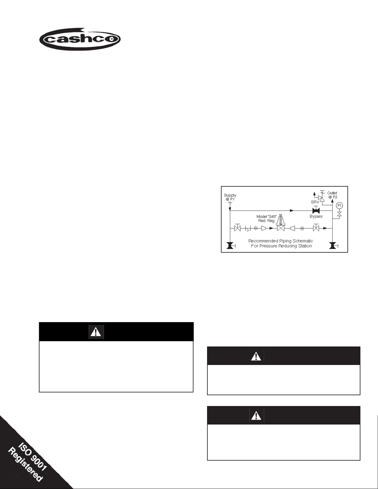
1. An inlet block valve should always be installed.
2. If service application is continuous such that
shut down is not readily accomplished, it is recommended that an inlet block valve, outlet block
valve, and a manual bypass valve be installed.
IOM-345
12-13
3. Pipe unions should be installed to allow removal
from piping.
4. An outlet pressure gauge should be located ap proxi mately ten pipe diameters downstream, and
within sight.
5. All installations should include a downstream relief device if the inlet pressure could exceed the
pres sure rating of any downstream equip ment or
the maximum outlet pressure rating of the unit.
CAUTION
DO NOT HYDROSTATIC TEST THRU AN IN STALLED
UNIT; ISOLATE REGU LA TOR FROM TEST. Internal
me chani cal damage could re sult. Refer to Technical
Bulletin Model 345, Table 5 for "emergency over pres sure
level" that will not do ir re pair able dam age. In ad di tion,
note on name plate that Inlet and Outlet pres sure ratings
are at dif fer ent levels.
6. Clean the piping of all foreign material including
chips, welding scale, oil, grease and dirt before
installing the regulator. Strainers are rec om mended.
7. In placing thread sealant on pipe ends prior to
en gage ment, assure that excess material is re moved and not allowed to enter the regulator upon
startup.
8. Flow Direction: Install so the fl ow direction match-
es the arrow cast on the main regulator body.
9. Basic Regulator - (Refer to Figure 1): Regu la tor
may be rotated around the pipe axis 360o. Rec ommended position is with spring chamber vertical
upwards. Orient such that the spring cham ber
vent hole does not collect rainwater or debris.
10. Regulators are not to be direct buried under ground.
CAUTION
Installation of adequate overpressure pro tec tion is recommended to pro tect the reg u la tor from overpressure and
all down stream equip ment from damage in the event of
regulator failure.
CAUTION
For welded installations, all internal trim parts, seals and
diaphragm(s) must be removed from regulator body prior to
welding into pipelne. The heat of fusion welding will damage non-metallic parts if not removed. NOTE: This does
not apply to units equipped with extended pipe nipples.
Page 2

SECTION III
III. PRINCIPLE OF OPERATION
Movement occurs as pressure variations register on the pressure piston. The registering pressure is the outlet, P2,
or downstream pressure. The range spring opposes pressure piston movement. As outlet pres sure drops, the range
spring pushes the pressure piston down, opening the port; as outlet pres sure in creases, the pressure piston pushes
up and the port opening closes.
SECTION IV
IV. STARTUP
1. Start with the block valves closed. A bypass
valve may be used to maintain outlet pressure
in the downstream system without changing the
fol low ing steps.
2. Relax the range spring by turning the T-bar handle
ad just ing screw counter clockwise (CCW) a mini mum of three (3) full revolutions. This reduces the
outlet (downstream) pressure set point.
3. If it is a "hot" piping system, and equipped with
a bypass valve, slowly open the bypass valve
to pre-heat the system piping and to allow slow
ex pan sion of the piping. Closely monitor outlet
(down stream) pressure via gauge to assure not
over-pressurizing. NOTE: If no bypass valve is
in stalled, extra caution should be used in starting
up a cold system; i.e. do everything slowly.
6. Continue to slowly open the inlet (upstream) block
valve until fully open.
7. Continue to slowly open the outlet (downstream)
block valve, especially when the downstream pip ing system isn't pressurized. If the outlet (down stream) pressure exceeds the desired pressure,
close the block valve and go to Step 2, then return
to Step 4.
8. When fl ow is established steady enough that the
outlet (downstream) block valve is fully open, begin to slowly close the bypass valve if installed.
9. Develop system fl ow to a level near its expected
normal rate, and reset the regulator set point by
turning the T-bar adjusting screw handle CW to
in crease outlet pressure, or CCW to reduce outlet
pressure.
4. Crack open the outlet (downstream) block valve.
5. Slowly open the inlet (upstream) block valve ob serv ing the outlet (downstream) pressure gauge.
Determine if the regulator is fl owing. If not, slowly
rotate the regulator T-bar ad just ing screw handle
clock wise (CW) until fl ow begins.
V. SHUTDOWN
1. On systems with a bypass valve, and where sys-
tem pressure is to be maintained as the regulator
is shut down, slowly open the bypass valve while
closing the inlet (upstream) block valve. Fully
close the inlet (upstream) block valve. (When on
bypass, the system pressure must be constantly
observed and manually regulated.) Close the
outlet (downstream) block valve.
10. Reduce system fl ow to a minimum level and ob-
serve set point. Outlet pressure will rise from the
set point of Step 9. The maximum rise in outlet
pres sure on decreasing fl ow should not exceed the
stated upper limit of the range spring by greater
than 10%; i.e. 500 to1000 psig (34.5 to 68.9 Barg)
range spring, at low fl ow the outlet pressure should
not exceed 1100 psig (75.8 Barg), if it does, consult
factory.
SECTION V
CAUTION
Do not walk away and leave a bypassed regulator unattended!
2. If the regulator and system are to both be shut-
down, slowly close the inlet (upstream) block
valve. Close the outlet (downstream) valve only if
regulator re mov al is required.
2 IOM-345
Page 3
SECTION VI
VI. MAINTENANCE:
WARNING
SYSTEM UNDER PRESSURE. Prior to per form ing any
maintenance, isolate the regulator from the system and
relieve all pressure. Fail ure to do so could result in personal injury.
A. General:
1. Maintenance procedures hereinafter are based
upon removal of the regulator unit from the pipe line
where installed.
2. Owner should refer to owner's procedures for
removal, handling, cleaning and disposal of nonreuseable parts, i.e. gaskets, etc.
3. Refer to Figure 1 for the basic regu la tor, metal seat
design and Figure 2 for a blow-up of the balanced
TFE trim.
B. Pressure Piston/O-Ring: Inspection/ Re place ment:
1. Securely install the body (1) in a vise with the spring
chamber (2) directed upwards.
7. Reverse steps 1 through 5 for reassembly. Make
sure spring chamber (2) is tightened fully down
against body (1).
C. Trim Replacement (For Metal Seated Units):
1. Install body (1) in a vise with the body cap (5) on
top.
2. Using a 5/16" Allen wrench, re move socket head
cap screws (21). Carefully remove body cap from
body.
3. Remove piston spring (17), piston (15 or 15.1),
cylinder (16 or 15.2) and cylinder gasket (18). Inspect parts for excessive wear, especially at seat
surfaces. Replace if worn, nicked, or depressed.
4. Remove body cap o-ring (13) and clean con tact ing
surface of body. Clean fl at mating sur faces of body
(1) to body cap (5) shoulder.
5. Clean debris from within regulator body (1) cav i ty.
Clean parts to be reused. NOTE: On regulators
originally supplied as "oxygen clean", option 34555, maintenance must in clude a level of clean li ness
equal to Cashco's cleaning stan dard #S-1134.
Contact factory for details.
WARNING
SPRING UNDER COMPRESSION. Prior to re mov ing
spring chamber, relieve spring com pres sion by back ing
out the T-bar adjusting screw. Failure to do so may result
in fl ying parts that could cause per sonal injury.
2. Relax range spring (14) by turning T-bar ad just ing
screw handle (6) CCW to release spring compression.
3. Grasp hexagon portion (w/proper wrench) of the
spring chamber (2) and turn CCW to re move.
4. Remove the thrust bearing (9), range spring (14),
and spring button (4).
5. Pull the pressure piston (3) directly out of the body.
Inspect the body quad ring (11) and body back up
ring (12). If nicked or scratched, re place. Apply
a light coating of lubricant to body quad ring (11)
when replacing.
6. Inspect pressure piston (3) to assure no de for ma tion due to over-pressurization. If deformed,
replace.
6. Replace cylinder gasket (18) on cylinder (16 or
15.2)
7. Reinstall the cylinder (16 or 15.2) and cylinder
gasket (18) into body cavity.
8. Slide the piston (15.1) slowly into place, as sur ing
that the piston (15.1) post slides into the pressure
piston (3).
9. Carefully place piston spring (17) directly on top of
the piston (15.1).
10. Install body cap o-ring (13) on body cap (5) and
carefully place body cap (5) into body (1). Re place
socket head cap screws (21) and tighten with a
5/16" Allen wrench. Rec om mended torque is as
fol lows:
Regulator Size Cap Screw Size Torque
1/2", 3/4" & 1"
(DN15, 20, 25)
3/8"-16-1"
skthd cap screw
50 ft./lbs.
(68 N-m)
NOTE: Never replace the socket head cap screws
(21) with just any bolting. Use only the proper size
and grade as replacement.
IOM-345 3
Page 4

11. Bench test unit for suitable operation. NOTE:
Regu la tors are not tight shutoff devices. Even if
pressure builds up beyond set point, a regu la tor
may or may not de velop bubble tight shutoff. In
general, tighter shutoff can be expected with com po si tion seat.
c. Remove the body cap o-ring (13) and clean
con tact ing sur face of body.
2. To check for seat leakage, follow same steps as
listed under Pressure Piston/O-ring Inspection/Replacement, except for the following guide lines:
12. Soap test around body cap (5) and body(1) for leak age. Test pressure should be a minimum of 100
psig (6.9 Barg) at the inlet and leakage de ter mined
by bubbles.
D. Trim Replacement (For TFE Seated Units):
1. Follow same steps as listed under trim re place ment
for metal seated units, except for the fol low ing
guidelines:
a. After removing the body cap(5) (C.2), inspect
the inside surface of the body cap for scratches
or nicks. These could result in leakage past the
quad ring (19) and backup ring (20). If worn
or scratched replace the body cap (5).
b. When inspecting parts for excessive wear
(C.3), assure there are no foreign particles
embedded in the tefl on seat. Inspect for nicks.
Inspect the backup ring (20) and quad ring (19)
on piston post.
a. Pour a small amount of water in on top of the
piston (through pressure piston bore in body).
Crack open inlet pressure (50 psig maximum)
to body and visu ally check for leakage by the
cylinder gasket (18), TFE seat (15), or the body
quad ring (19). After inspection, assure that
water is removed before completing assembly
and installing in line.
NOTE: When piston (15) assemblies are used with comp
seats, Cashco, Inc. does not recom mend attempting to
remove the comp seat. If composition seat is damaged,
replace entire piston assembly.
SECTION VII
Vll. TROUBLE SHOOTING GUIDE
1. Erratic operation.
A. Oversized regulator; inadequate rangeability. A1. Check actual fl ow conditions, re-size regulator for minimum and maximum
fl ow.
A2. Increase fl ow rate.
A3. Decrease regulator pressure drop; decrease inlet pressure by placing a
throttling orifi ce in inlet piping union.
A4. Install next step higher range spring.
A5. Before replacing regulator contact factory.
B. Worn piston/cylinder; inadequate guiding. B. Replace trim.
C. Weakened/broken piston spring. C. Replace piston spring.
2. Sluggish operation.
A. Plugged piston balance port. A. Remove trim and clean balance port.
B. Fluid too viscous. B. Heat fl uid. Contact factory.
Possible Causes Remedies
RemediesPossible Causes
4 IOM-345
Page 5

3. Downstream Pressure will not reach desired setting.
RemediesPossible Causes
A. Regulator undersized. A1. Confi rm by opening bypass valve together with regulator.
A2. Check actual fl ow conditions, re-size regulator; if regulator has inadequate
capacity, replace with larger unit.
B. Plugged trim. B. Remove trim and check for plugged holes in cylinder.
C. Incorrect range spring (screwing in CW of adjust- C. Replace range spring with proper higher range. Contact factory.
ing screw does not allow bringing pressure level
up to proper level).
D. Too much droop. D1. Review droop expected.
D2. Contact factory.
E. Restricted pressure piston movement. E. Assure no moisture in spring chamber at tem pera tures below freeze point.
Assure no dust or debris entering vent openings.
4. Leakage through the spring chamber vents.
RemediesPossible Causes
A. Failure of body quad ring and body backup A. Inspect the pressure piston, body quad ring and body backup ring.
ring. If scratched, nicked, or deformed - replace.
5. Excessive pressure downstream.
Possible Causes Remedies
A. Regulator not closing tightly. A.1. Inspect the seating. Clean and lap metal seat surfaces; replace if lapping
does not remedy. If composition seats are depressed, nicked or embedded
with debris, replace trim.
A2. Inspect guides in body cap (Balanced trim). If damaged, replace body cap
and/or piston, quad ring and back up ring.
B. Downstream block. B. Check system; isolate (block) fl ow at regulator inlet - not outlet. Relocate
regulator if necessary.
C. No pressure relief protection. C. Install safety relief valve, or rupture disc.
D. Restricted pressure piston movement. D. Assure no moisture in spring chamber at temperatures below freeze point.
Assure no dust or debris entering vent openings.
6. Excessive seat leakage.
Possible Causes Remedies
A. Foreign matter on seating surface, erosion A. Inspect and replace damaged parts.
of seating surface, scratched body cap.
B. Balanced trim B. Inspect piston quad ring and back up ring. Replace if damaged.
IOM-345 5
Page 6

SECTION VIII
VIII. ORDERING INFORMATION
NEW REPLACEMENT UNIT vs PARTS "KIT" FOR FIELD REPAIR
To obtain a quotation or place an order, please retrieve the Serial Number and Product Code that was stamped
on the metal name plate and attached to the unit. This information can also be found on the Bill of Material
("BOM"), a parts list that was provided when unit was originally shipped. (Serial Number typically 6 digits).
Product Code typical format as follows: (last digit is alpha character that refl ects revision level for the product).
–
NEW REPLACEMENT UNIT:
Contact your local Cashco, Inc., Sales Rep re sen ta tive with the Serial Number and Product code.
With this information they can provide a quotation
for a new unit including a complete description,
price and availability.
CAUTION
Do not attempt to alter the original construction of any
unit without assistance and approval from the factory. All
purposed changes will require a new name plate with appropriate ratings and new product code to accommodate
the recommended part(s) changes.
PARTS "KIT" for FIELD REPAIR:
Contact your local Cashco, Inc., Sales Rep re sen ta tive with the Serial Number and Product code.
Identify the parts and the quantity required to repair
the unit from the "BOM" sheet that was provided
when unit was originally shipped.
–
7
NOTE: Those part numbers that have a quantity indicated
under "Spare Parts" in column "A” refl ect minimum
parts required for inspection and rebuild, - "Soft
Goods Kit". Those in column “B” include minimum
trim replacement parts needed plus those "Soft
Goods" parts from column "A".
If the "BOM" is not available, refer to the crosssectional drawings included in this manual for part
identifi cation and selection.
A Local Sales Representative will provide quotation
for appropriate Kit Number, Price and Availability.
The contents of this publication are presented for informational purposes only, and while every effort has been made to ensure their accuracy, they are not to be
construed as warranties or guarantees, express or implied, regarding the products or services described herein or their use or applicability. We reserve the right to
modify or improve the designs or specifi cations of such product at any time without notice.
Cashco, Inc. does not assume responsibility for the selection, use or maintenance of any product. Responsibility for proper selection, use and maintenance of any
Cashco, Inc. product remains solely with the purchaser.
6 IOM-345
Page 7

Figure 1: Basic Model 345 with metal seat design.
Item No. Description Item No. Description
1 Body 13 Body Cap O-Ring ‡
2 Spring Chamber 14 Range Spring
3 Pressure Piston 15 Piston - Comp
4 Spring Button 15.1 Piston-Metal ‡
5 Body Cap 15.2 Cylinder-Metal ‡
6 Adjusting Screw 16 Cylinder-Comp
7 Set Screw 17 Piston Spring ‡
8 T-Bar Handle 18 Cylinder Gasket ‡
9 Thrust Bearing 19 Pistion Quad Ring
10 Name Plate 20 Piston Backup Ring
11 Body Quad Ring ‡ 21 Socket Head Cap Screw (6)
12 Body Backup Ring ‡
Figure 2: Composition Seat Design
‡ Available with Parts Kit B
IOM-345 7
Page 8

Cashco, Inc.
P.O. Box 6
Ellsworth, KS 67439-0006
PH (785) 472-4461
Fax. # (785) 472-3539
www.cashco.com
email: sales@cashco.com
Printed in U.S.A. IOM-345
Cashco GmbH
Handwerkerstrasse 15
15366 Hoppegarten, Germany
PH +49 3342 4243135
Fax. No. +49 3342 4243136
www.cashco.com
Email: germany@cashco.com
Cashco do Brasil, Ltda.
Al.Venus, 340
Indaiatuba - Sao Paulo, Brazil
PH +55 11 99677 7177
Fax. No.
www.cashco.com
Email: brazil@cashco.com
 Loading...