

Page 1
INSTALLATION, OPERATION AND MAINTENANCE MANUAL
Model 3200
Pressure / Vacuum Relief Vent
w/ Pipeaway Connection
SECTION I
I. 3000 SERIES DESIGN AND FUNCTION
IOM-3200
08-10
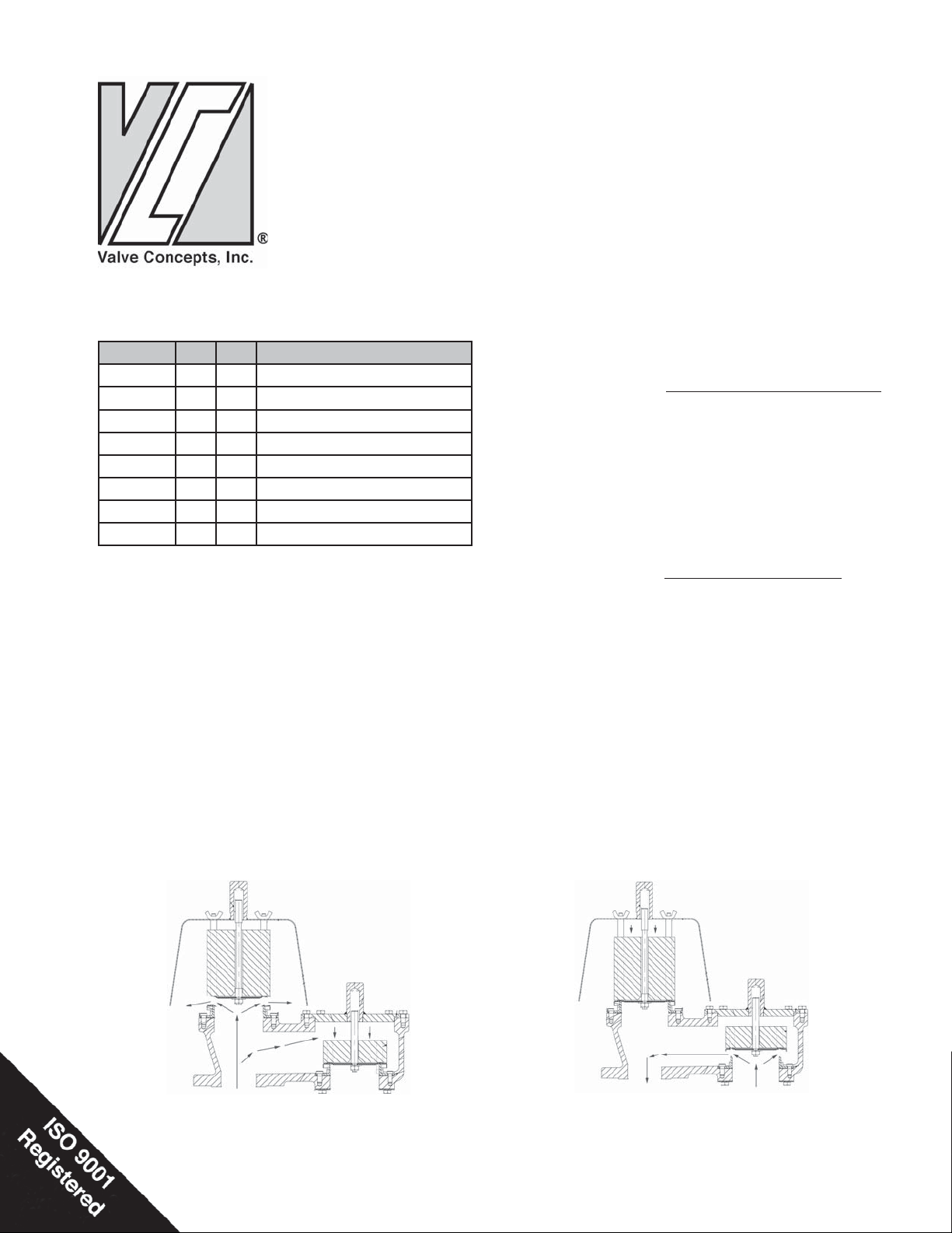
MODEL P V DESCRIPTION
3100 P V Vent to Atmosphere
3200 P V Vent to Header
3300 V Top Mounted
3400 P Vent to Atmosphere
3500 P Vent to Header
3600 V Side Mounted
3700 P Emergency/Manhole Cover
3800 P Emergency/Top Guided Relief
Models 3100 through 3600 Pressure and /or Vacuum
Vents are used for the normal venting requirements.
Normal venting is defi ned as venting required
because of operational requirements (i.e. fi lling and
emptying the tank) or atmospheric changes. Models
3700 and 3800 Emergency Relief Vents are used to
meet venting required when an abnormal condition,
such as an external fi re or such as ruptured internal
heating coils, exist either outside or inside the tank.
All of these devices are sized in accordance with API
Standard 2000. Improperly specifi ed relief vents may
result in structural damage to the tank or system and
can cause severe personal injury or death.
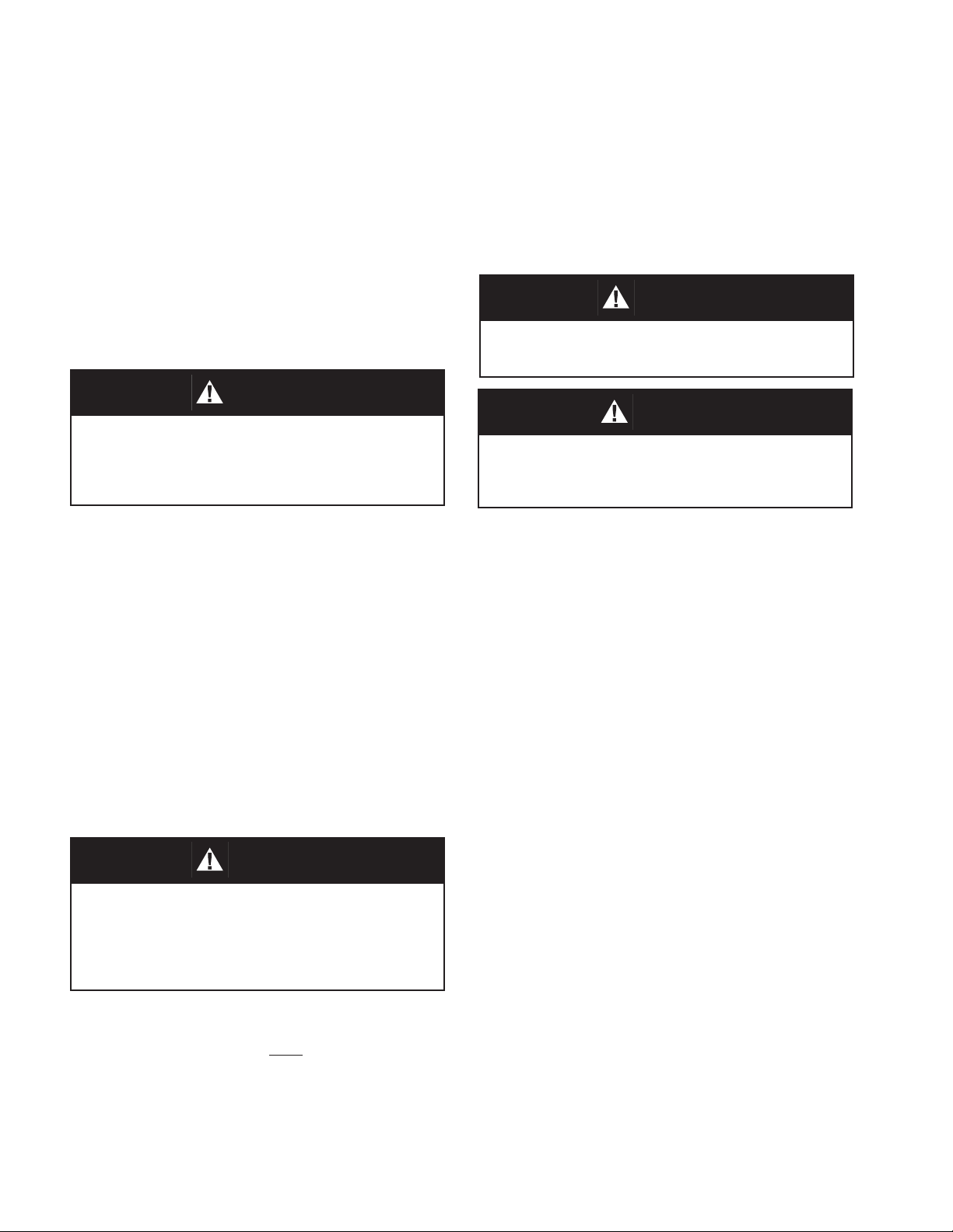
Figure 1 illustrates the operation of the Pressure/
Vacuum Relief Vent under overpressure conditions.
As the tank pressure increases as a result of product
being pumped into the tank and/or because of thermal
expansion of the product and vapors, the pressure
pallet remains closed until the set pressure of the
vent is reached. When the tank pressure reaches the
pressure setting of the vent, the pressure pallet lifts
allowing the tank pressure to bleed off.
Figure 2 illustrates the operation of the Pressure/
Vacuum Relief Vent under vacuum conditions.
As the tank pressure decreases as a result of product
being pumped out of the tank and/or because of
thermal contraction of the product and vapors, the
vacuum pallet remains closed until the set vacuum of
the vent is reached. When the tank vacuum reaches
the vacuum setting of the vent, the vacuum pallet lifts
allowing air to be drawn into the tank.
Figure 1 - Pressure Relief
Figure 2 - Vacuum Relief
Page 2
II. SAFETY WARNINGS
SECTION II
Tank or system protection is the primary function of
the weight loaded Pressure and/or Vacuum Relief
Vent. It must be selected to meet the total pressure
and vacuum fl ow requirements within the Maximum
Allowable Working Pressure and Vacuum of the
system on which it is installed. Consult API Standard
2000 for tank protection sizing procedures. Improperly
specifi ed relief vents may result in structural damage
to the tank or system and can cause severe personal
injury or death.
CAUTION
DO NOT attempt to remove the vent from the tank or
process vessel without fi rst bleeding all pressure from
the system. ALTERNATIVE MEANS OF PRESSURE
RELIEF MUST BE PROVIDED WHEN THE VENT IS OUT
OF SERVICE.
SECTION III
III. INSPECTION AND STORAGE
When Pipe-Away relief vents are used, backpressure
in the header system will affect the set point of
weight loaded vents by the amount of the header
pressure. Maximum possible header pressure must
be considered when sizing the pressure relief vent.
CAUTION
DO NOT change pressure ratings by adding additional weights to the pallet assembly without consulting
Cashco Inc. or your VCI representative.
CAUTION
DO NOT mix pressure/vacuum weight assemblies. Failure to ensure that both weight assemblies are installed
in the correct location can change the pressure and
vacuum relief settings. This can cause tank failure.
The pressure/vacuum relief vent is carefully packaged
to prevent damage or contamination during shipping.
Inspect the equipment when it is received and report
any damage to the carrier immediately. The vent
should be stored with all the protective fl ange covers
SECTION IV
IV. INSTALLATION
WARNING
The vent must be installed in a vertical position as
shown in Figure 1. The tank nozzle on which the vent
is mounted should have the same nominal diameter as
the venting device. It is recommended that the tank
nozzle fl ange face be within 1 degree of horizontal for
best performance of the venting device.
The 3000 Series Vents are designed to mate with a
150 lb ASME fl ange. Torque guidelines are provided
in Table 1. The Vents are NOT rated for full fl ange
pressure and do not require high bolting torque.
in place. Make sure that any loading weights that
might have been shipped separately, to protect the
vent during shipping, are accounted for and stored
with the vent. These weights, when required, will be
installed during installation. See Section IV.
If loading weights were shipped separate from the
vent, make sure to install on the appropriate pallet.
Inspect the gasket seating surface of the tank nozzle
fl ange. It must be clean, free of scratches, corrosion,
tool marks and fl at.
FRP and Aluminum vents are furnished with fl at
faced fl anges. It is recommended that they be
installed on mating fl at face fl anges with a full faced
gasket. If the fl at face of the vent is sealing against
a raised face steel fl ange, a spacer or fi ller ring must
be used to fi ll the annular space of the raised face
steel fl ange.
Before installing the 3000 Series Vent, remove all
packing materials from inside and outside the vent.
2
Make sure the gasket is suitable for the application
and is in good condition.
IOM-3200
Page 3
WARNING
Minimum clearance between tank roof and vacuum
inlet port must be at least equal to the vents’ nominal fl ange bore. Tank nozzle bore must be greater
than or equal to vent inlet fl ange bore. Inlet and
outlet piping loads must be supported by appropriate structural supports, NOT by the vent body.
Fiberglass fl anges 2 inch to 12 inch require the use
of a full-face 150 lb. gasket. For full face gaskets,
we recommend the use of a 1/8-inch Gortex gasket.
Center the gasket within the bolt circle of the tank
fl ange and carefully set the vent on the fl ange nozzle
and align the bolt holes.
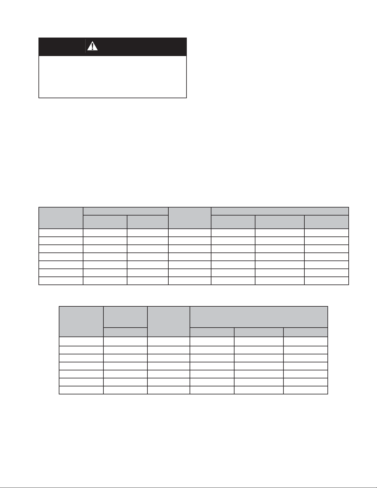
TABLE 1
All Torque Requirements Are Dependant On Gasket Material
Bolt Torque and Stud Specifi cations - ASME #150 Flange Connections
All stud threads must be lubricated to obtain proper
torque results. A washer should be used under each
stud nut.
Install the studs, washers and nuts and tighten nuts
hand tight. Check proper alignment of fl ange faces.
Misalignment of fl ange faces will cause bending
stresses at the fl ange and fl ange joint and damage
may result. Correct any misalignment prior to
applying torque to nuts.
All nuts must be tightened in proper sequence and
equal increments. Proceed through the tightening
sequence until the recommended torque is attained.
Recheck the torque on each bolt in the same
sequence as bolts previously tightened may have
relaxed through the torque sequence.
MOUNTING
FLANGE
2” 30 (0.35) 60 (0.69) 4 5/8” - 11 2.50” 2
3” 54 (0.62) 108 (1.24) 4 5/8” - 11 2.75” 2
4” 42 (0.48) 78 (0.89) 8 5/8” - 11 2.75” 4
6” 90 (1.04) 150 (1.72) 8 3/4” - 10 3.00” 4
8” 126 (1.45) 228 (2.62) 8 3/4” - 10 3.00” 4
10” 138 (1.59) 246 (2.83) 12 7/8” - 9 3.50” 6
12” 186 (2.14) 348 (4.01) 12 7/8” - 9 3.50” 6
BOLT TORQUE - Ft. lbs. NUMBER
RAISED FACE FLAT FACE THREAD UNC STUD LENGTH *QUANTITY
BOLTS
TOTAL
STUD SPECIFICATIONS
Bolt Torque and Stud Specifi cations for FRP Flanges Drilled to ASME #150 Flange Connections
BOLT
MOUNTING
FLANGE
2” 20 4 5/8” - 11 2.50” 2
3” 20 4 5/8” - 11 2.75” 2
4” 20 8 5/8” - 11 2.75” 4
6” 30 8 3/4” - 10 3.00” 4
8” 30 8 3/4” - 10 3.00” 4
10” 30 12 7/8” - 9 3.50” 6
12” 30 12 7/8” - 9 3.50” 6
TORQUE -
Ft. lbs.
FLAT FACE THREAD UNC STUD LENGTH *QUANTITY
NUMBER
BOLTS TO-
TAL
STUD SPECIFICATIONS
*
*
Blind tapped holes only (Models 3100, 3200, and 3300). Use standard ASME stud length for other holes.
*
IOM-3200
3
Page 4

SECTION V
V. MAINTENANCE
Tank or system protection is the primary function
of the weight loaded Pressure and/or Vacuum
Relief Vent. As a safety device, it is very important
that maintenance/inspection be done on a regular
interval. Maintenance should only be done by a
qualifi ed technician. Valve Concepts recommends
that all service be performed at the factory or a
factory authorized repair center. For information on
repair centers in your area, please contact factory.
To Dis-assemble: Remove cover bolts (22), covers
(2) and cover gaskets (12).
Inspect cover for corrosion, damage, or product
build up. Clean with a suitable solvent, replace as
necessary.
NOTE: During re-assembly, install new cover
gaskets (12) (5/32-inch diameter Gortex rope joint
sealant). For FRP material - bolting (22) for covers
(2) should be tightened to 50 in. - lbs. (5.6 Nm).
Remove pressure and vacuum pallet assemblies,
including any loading weights (18) that may be on
the pallets (4). NOTE: As the pallets are removed
from the vent, identify each assembly (including the
stack of weights) by tagging as “pressure” side or
“vacuum” side.
Clean and inspect pallet (4) assemblies. Inspect the
diaphragms (5) and replace if necessary.
To Replace Diaphragms: Place stems (9,10) in a
vise with threaded end up. Remove cotter pin (61),
nut (23), lock-washer (19) and washer (24).
Lift up to remove diaphragm plate (6,28) and
diaphragms (5). NOTE: Apply TFE paste to threads
of the stem and around hole on the pallets (4).
Install new diaphragms (5). Re-install diaphragm
plate (6,28), washer (24), lock-washer (19) and
tighten nut (23) on stem. Insert cotter pin (61)
through hole in stem and secure.
To Remove Seat Rings/Gaskets: Rotate bolts
(11) CCW and remove. Remove guides (8)(16)
and spacers (69) (Use slot on top of guides and
rotate CCW.) Mark the location of these items on
the appropriate seat ring (3) for reference at reassembly.
CAUTION
The pipeaway body (20) is no longer fastened securely
to the body (1) and could fall and cause severe personal injury and material damage.
Lift up to remove seat rings (3) and gaskets (13).
Inspect guides (8)(16) and inside of the body cavity
(1) for any corrosion or product build up. Clean if
necessary.
Apply TFE paste to both sides of new gaskets and
install in body (1).
To Remove Lower Gasket: Separate pipeaway
body (20) from body (1). Remove lower gasket (13)
and clean sealing surfaces of both parts. Apply TFE
paste to both sides of new gasket (13) and install in
body (1).
Re-assemble vent in reverse order, making sure
that the pressure and vacuum pallet(s) and loading
weights are in their proper location. Tighten bolts
(11), guides (8)(16) to 15 ft. lbs. (20.3 Nm). When
installing the covers, ensure the pressure stem
(10) and vacuum stem (9) are inserted in the stem
guides.
WARNING
When assembling a P/V vent, always put the
pressure (long stem) and vacuum (short
stem) pallet assemblies back in their original
location and ensure that the stem is straight and fi ts
into the guide in the cover or weatherhood.
If the pressure and vacuum pallet assemblies are mixed
at assembly, the settings will be changed and the fl ow
for the vacuum side will be restricted.
Inspect and clean pressure / vacuum seat ring(s)
(3). Check seat surface for any nicks, corrosion,
pitting or product build up. Seat surfaces must be
clean and smooth for vent to perform properly.
4
If the stem is cocked at an angle, pallet lift may be completely blocked. An over-pressure can occur if any of
these three conditions happens. This can cause a tank
failure, severe personal injury and material damage.
To Remove Inlet Screen: Rotate bolts (15) CCW
and remove. Inspect and clean screen (14) and
reinstall to body (1).
IOM-3200
Page 5

VI. TEST PROCEDURE
To Calculate Weight of Pallet Assembly:
Table 2 shows the pallet weight per unit of pressure
or vacuum setting. The total pallet assembly weight
is determined by multiplying the desired set point (in
the appropriate units) by the incremental weight per
unit listed in Table 2.
For Example:
4” Model 3204 CS - if the desired setting is 5 oz/in
Table 2 shows that for a 4” vent, the pallet would
weigh 2.05 lb per oz/in
2
SECTION VI
ACCEPTANCE CRITERIA:
The pressure gauge shall maintain a pressure equal
to or greater than 90% of set pressure for a one
minute period while the specifi ed fl ow rate is main-
tained. Note: Valve Concepts acceptance criteria
exceed the requirements of API. API 2521 states
that if the rate of leakage does not exceed ½ SCFH
for 6 inch size and smaller, or 5 SCFH for 8 inch and
larger, at 75% of set point, then a vent is considered
2
satisfactory for all practical purposes.
If the vent fails to meet the 90% criteria, it must
be disassembled and the seat, pallet, and or diaphragms repaired or replaced.
So the pallet assembly for a 5 oz/in2 setting would
weigh: 2.05 lbs/oz/in2 x 5.0 oz./in2 - 10.25 lbs
A test report should be completed for each vent. The
report should indicate the total pallet weight and the
pressure achieved at the Test Flow Rate for both
Valve Concepts allows a deviation from this
theoretical weight of ± 3.0%.
pressure and vacuum. Other general information
such as serial number, model number, material of
construction, set pressure and vacuum, etc. should
To Determine Diaphragm/Seat Leakage:
be included in the report.
After both pallets’ weight has been determined and
verifi ed for the required setting, reassemble the vent
and mount on a Tank Vent Test Stand and slowly
The test report should be kept with the Valve Maintenance Records.
raise the pressure at the fl ow rate of 1.0 SCFH.
TABLE 2
Nominal Pallet Assembly Weight Per Unit of Pressure lbs (kg)
SET Point
Units
1.0 oz/in
1.0 in WC 0.15 (0.07) 0.32 (0.14) 0.54 (0.24) 1.18 (0.53) 2.03 (0.92) 3.15 (1.43) 4.46 (2.02) 5.30 (2.40)
1.0 mbar 0.13 (0.06) 0.13 (0.06) 0.22 (0.10) 0.48 (0.22) 0.81 (0.37) 1.26 (0.57) 1.79 (0.81) 2.13 (0.97)
2” VTA 2” PV 3” 4” 6” 8” 10” 12”
Lb (kg) Lb (kg) Lb (kg) Lb (kg) Lb (kg) Lb (kg) Lb (kg) Lb (kg)
2
0.25 (0.11) 0.55 (0.25) 0.93 (0.42) 2.05 (0.93) 3.50 (1.59) 5.45 (2.47) 7.71 (3.50) 9.17 (4.16)
VALVE SIZE
TABLE 3
Maximum Pressure Setting in oz/in2 Vs. Diaphragm mil
IOM-3200
Line Size 10 mil 20 mil 30 mil 40 mil
2” VTA 7.00 34.00 40.00 n/a
2” P/V 4.50 23.50 33.00 40.00
3” P/V 3.50 18.00 25.00 40.00
4” P/V 2.25 12.00 17.00 40.00
6” P/V 1.75 9.25 13.25 40.00
8” P/V 1.75 7.50 10.50 40.00
10” P/V 1.25 6.25 8.75 40.00
12” P/V 1.00 5.75 8.00 40.00
5
Page 6

SECTION VII
VII. ORDERING INFORMATION
NEW REPLACEMENT UNIT vs PARTS "KIT" FOR FIELD REPAIR
To obtain a quotation or place an order, please retrieve the Serial Number and Product Code that was stamped
on the metal name plate and attached to the unit. This information can also be found on the Bill of Material
(“BOM”), a parts list that was provided when unit was originally shipped. (Serial Number typically 6 digits).
NEW REPLACEMENT UNIT:
Contact your local Cashco, Inc., Sales Rep re sen ta tive with the Serial Number, Product code and the
pressure/vacuum settings. With this information they
can provide a quotation for a new unit including a
complete description, price and availability.
CAUTION
Do not attempt to alter the original construction of any
unit without assistance and approval from the factory.
All proposed changes will require a new name plate with
appropriate ratings and new product code to accommodate the recommended part(s) changes.
PARTS "KIT" for FIELD REPAIR:
Contact your local Cashco, Inc., Sales Rep re sen ta tive with the Serial Number and Product
code. Identify the parts and the quantity required
to repair the unit from the “BOM” sheet that
was provided when unit was originally shipped.
NOTE: Those part numbers that have a quantity indi-
cated under "Spare Parts" in column "A” refl ect
minimum parts required for inspection and
rebuild, - "Soft Goods Kit". Those in column “B”
include minimum trim replacement parts needed
plus those "Soft Goods" parts from column "A".
If the "BOM" is not available, refer to the crosssectional drawings included in this manual for
part identifi cation and selection.
A Local Sales Representative will provide
quotation for appropriate Kit Number, Price
and Availability.
6
IOM-3200
Page 7

MODEL 3200 PRESSURE/VACUUM RELIEF VENT WITH PIPE-AWAY
ITEM NO. METAL PARTS LIST FRP PARTS LIST
1 Body Body
2 Cover Assembly Cover Assembly
3 Seat Ring Integral Part of Item 1
4 Pallet Pallet
5 Diaphragm Diaphragm
6 Diaphragm Retainer Plate - Pressure Diaphragm Retainer Plate - Pressure
8 Vacuum Pallet Guide Integral Part of Item 1
9 Vacuum Pallet Stem Integral Part of Item 4
10 Pressure Pallet Stem Integral Part of Item 4
11 Seat Ring Bolts Not Required
12 Cover Gasket (Gortex Rope) Cover Gasket (Gortex Rope)
13 Seat Ring Gasket Not Required
14 Inlet Screen Assembly Not Required
15 Inlet Screen Bolts Not Required
16 Pressure Pallet Guide Integral Part of Item 1
18 Weight Weight
19 Lock Washer Not Required
20 Pipe Away Body Integral Part of Item 1
21 Drain Plug Not Required
22 Cover Bolts Studs, Nuts, and Washers
23 Pallet Nut/Bolt Pallet Nut
24 Plain Washer Not Required
28 Diaphragm Retainer Plate - Vacuum Diaphragm Retainer Plate - Vacuum
31 Pipe Plug Not Required
42 Stiffener Plate Not Required
61 Cotter Pin Not Required
69 Stud Spacer Not Required
73 Washer Washer
74 Nut Nut
75 Stud Stud
IOM-3200
7
Page 8

Valve Concepts, Inc./ Cashco, Inc.
607 W. 15th Street
Ellsworth, KS 67439
PH (785) 472-4461
FAX (785) 472-3539
www.cashco.com
email: vcisales@cashco.com
Printed in U.S.A. Model 3200
 Loading...