

Casella USA
17 Old Nashua Rd #15
Amherst, NH 03031 USA
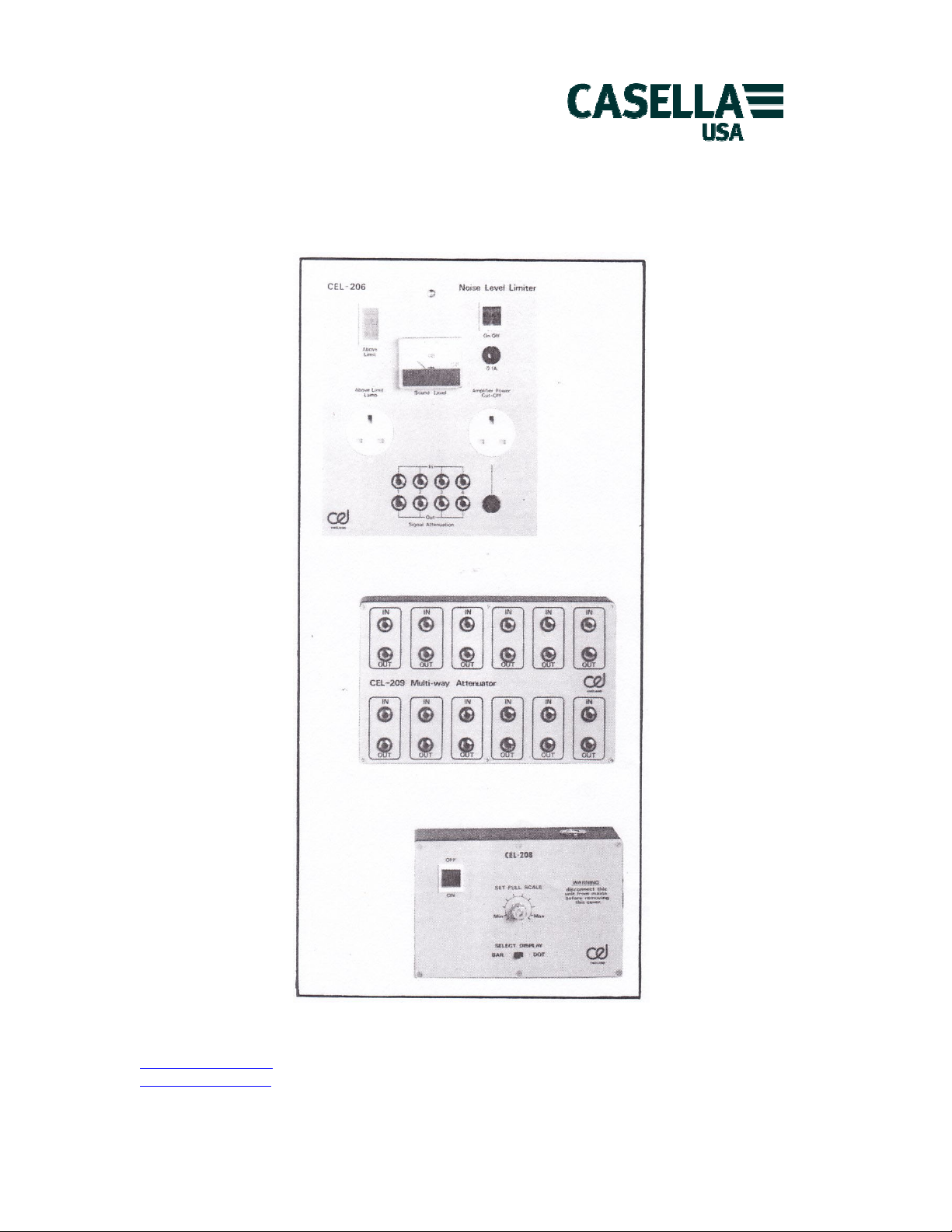
CEL-206 NOISE LEVEL LIMITER
CEL-208 MULTI THRESHOLD UNIT
CEL-209 MULTI WAY ATTENUATOR
info@casellausa.com
www.casellausa.com
HANDBOOK
Page 1 of 16 Tel: (800) 366-2966
2 Mar 2009 Fax: (603) 672-8053
Casella USA
17 Old Nashua Rd #15
Amherst, NH 03031 USA
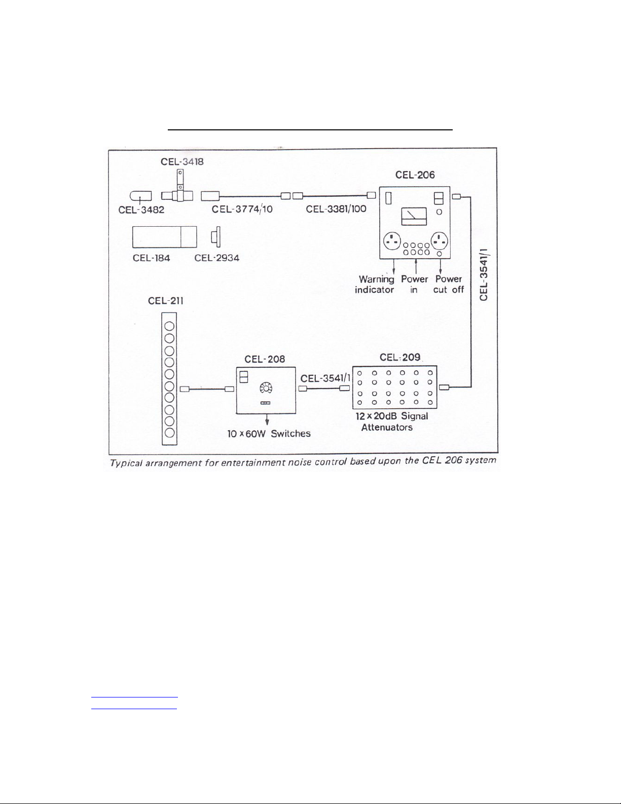
Block diagram of typical CEL-206 System Installation
info@casellausa.com
www.casellausa.com
Page 2 of 16 Tel: (800) 366-2966
2 Mar 2009 Fax: (603) 672-8053

Casella USA
17 Old Nashua Rd #15
Amherst, NH 03031 USA
CONTENTS
CEL-206 Noise Level Limiter Page
Introduction 4
1 Technical Description 4
2 Installation 5
2.1 Schedule of Parts 5
2.2 Microphone System 5
2.3 Main Control Unit 6
3 Calibration 7
4 Operation 9
5 Specification 9
CEL-208 Multi Threshold Unit
Introduction 9
1 Technical Description 9
2 Installation 10
2.1 Schedule of Parts 10
2.2 Connection and Operation 10
3 Specification 12
CEL-209 Multi Pole Attenuator
Introduction 12
1 Technical Description 12
2 Installation 12
2.1 Schedule of Parts 12
2.2 Connection and Operation 12
3 Specification 13
4 Manufacturing Servicing and Warranty Arrangements 14
5 Post Production Developments 15
6 Calibration Certificate 16
info@casellausa.com
www.casellausa.com
Page 3 of 16 Tel: (800) 366-2966
2 Mar 2009 Fax: (603) 672-8053

Casella USA
17 Old Nashua Rd #15
Amherst, NH 03031 USA
CEL-206 DISCO NOISE LEVEL LIMITER
INTRODUCTION
The problems of entertainment noise are now well established both in terms of the
nuisance element in respect of nearby residents and the health hazard to employees
and patrons alike. It is to eliminate problems in these areas that the CEL-206 has
been introduced. A comprehensive design study has been undertaken to ensure that the
system is practical and accurate in a wide range of installations.
The basic approach is to monitor the noise level in the required noise sensitive
area, which can be either indoors or outside the premises, and display the measured
level on a wide dynamic range sound level meter. This level is continually compared
against a preset threshold level which will, if exceeded, light a warning indicator.
If after a short period the levels have not been reduced a trigger is latched that
will introduce attenuation into the signal leads for a period of approximately 20
seconds. If necessary, this trigger can be used to cut the main supply to the audio
power amplifiers thereby completely shutting off the noise source for a short
period. The object of these arrangements is to discipline performers to keep within
agreed sound levels.
1 TECHNICAL DESCRIPTION
The CEL-206 system is provided as standard with a 0.5 inch microphone and integral
pre-amplifier assembly complete with a 10 metre cable. A mounting bracket is
provided to enable the microphone to be located in the required monitoring position
and extension cables of any length up to 100 metres are available under the part
number CEL-3381. A security link is wired throughout the microphone cable such that
the threshold level will be triggered if the microphone is disconnected for any
reason. The main electronics package is housed within a robust steel enclosure that
may be mounted onto a wall and directly wired into the mains electricity supply. It
comprises a wide range sound level meter that covers 60-110dB; however, for special
applications this may be offset during field calibration to cover levels between 45115dB. This calibration is performed by the supervising authority using a CEL-184
Acoustic Calibrator and at the same time the threshold level is set the unit is then
closed and, if necessary, a seal attached via the link provided. The threshold level
may be set anywhere within the instrument's dynamic range and may be in terms of a
dB(A) level where airborne sound is the prime consideration or dB Flat (Linear)
where the main nuisance is in respect, of structure borne noise.
During the performance it is obviously difficult to keep an eye on the meter and
limit lamp mounted on the CEL-206 so facilities are provided for a power outlet to
be activated in parallel with the warning indicator and this can be connected to a
lamp on stage that can be sited so as to be clearly visible to the performers.
info@casellausa.com
www.casellausa.com
Page 4 of 16 Tel: (800) 366-2966
2 Mar 2009 Fax: (603) 672-8053

Casella USA
17 Old Nashua Rd #15
Amherst, NH 03031 USA
For those applications where a more accurate system is required the CEL-208 multithreshold unit may be connected to the noise level limiter. This will indicate the
levels in 10 steps by means of a series of power contact closures enabling, for
example, calibrated 'light columns' to be constructed as part of the light show.
Such an arrangement gives the artistes a clear and continual real-time picture of
the sound level in the auditorium.
The CEL-206 is provided with two conventional power outlets, one activated when the
threshold is exceeded and the other disconnected after the delay period. These are
for the remote warning and amplifier power cut-off respectively and, if required,
they can be directly wired via knock-outs in the enclosure. The internal relays are
suitable for switching the power in small and medium sized installations and for
large systems, etc, they are used to control external power actuators. Similarly, where signal
attenuation control is being employed, up to four lines are controlled direct but, if more are
required, the CEL-209 Automatic Multi-Pole Attenuator box may be connected to extend the number up
to 28. (12 ways per CEL-209 hence two may be operated simultaneously).
2 INSTALLATION.
2.1 Schedule of parts
The description CEL-206 Noise Limiter complete refers to the following items and
should be checked upon receipt against this schedule:
CEL-206 Noise Level Limiter
CEL-3418 Microphone and preamplifier assembly c/w mounting bracket
CEL-3774 Extension cable 10m
Allen Key
In addition the following accessory items will be found useful and these will
be shown separately on advice notes, etc:
CEL-3381/20 Microphone Extension Cable - 20m
CEL-3482 Windshield
CEL-184 Calibrator (NB coupler type CEL-2834 required)
CEL-208 Multi-threshold Unit
CEL-209 Multi-pole Attenuator Box
CEL-211 Light Column for use with CEL-208
2.2 Microphone System
The important consideration in respect of microphone location is to ensure that
it reflects the actual noise level that is to be controlled.
info@casellausa.com
www.casellausa.com
Page 5 of 16 Tel: (800) 366-2966
2 Mar 2009 Fax: (603) 672-8053
 Loading...