

Casella CEL CEL-193 User Manual
Casella USA
17 Old Nashua Rd #15
Amherst, NH 03031 USA
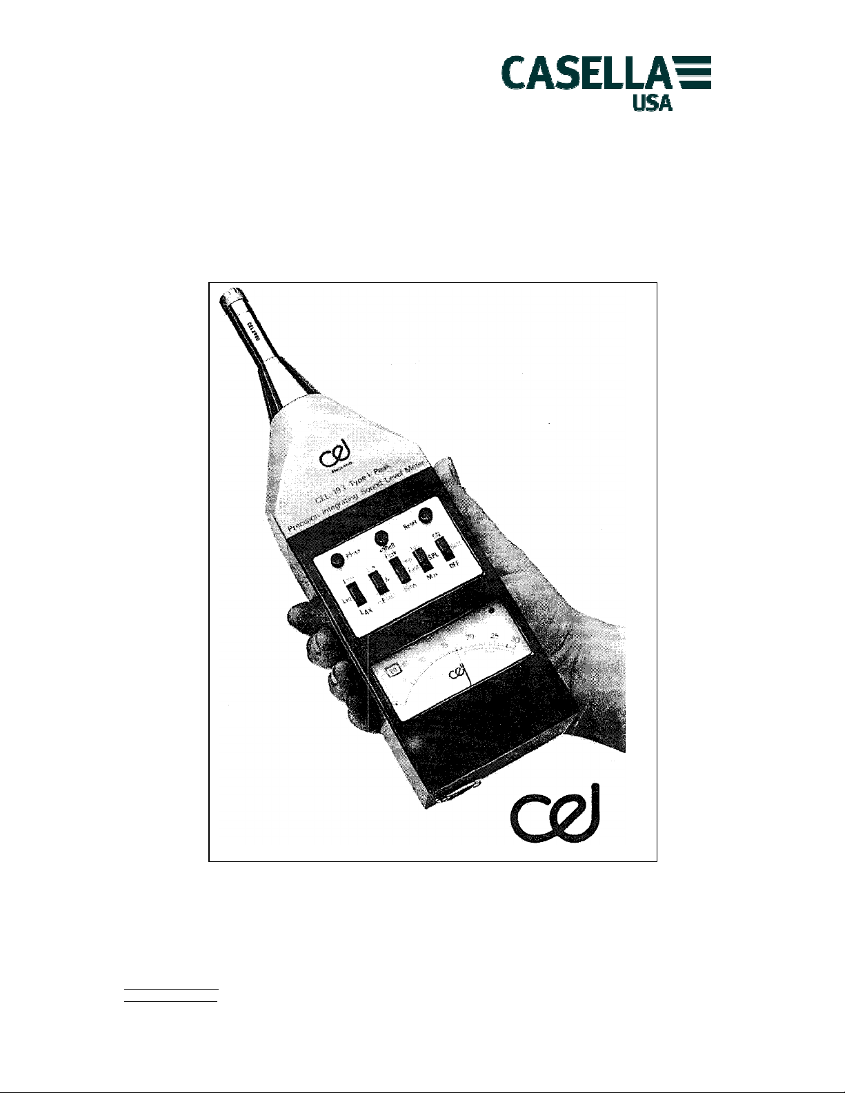
Integrating Sound Level Meter
CEL-193
Precision Impulse
Handbook
info@casellausa.com Page 1 of 20 Tel: (800) 366-2966
www.casellausa.com
2 Mar 2009 Fax: (603) 672-8053

Casella USA
17 Old Nashua Rd #15
Amherst, NH 03031 USA
This page is intentionally blank
info@casellausa.com Page 2 of 20 Tel: (800) 366-2966
www.casellausa.com
2 Mar 2009 Fax: (603) 672-8053

Casella USA
17 Old Nashua Rd #15
Amherst, NH 03031 USA
CONTENTS
Page
1 Schedule of Parts 4
2 Preparing the Instrument for Use 4
2.1 Connection of Batteries and Microphone 4
2.2 Controls and Indicators 5
2.3 Calibration Procedure 7
3 Using the CEL-193 as a Sound Level Meter 7
3.1 Attenuator Setting 8
3.2 Time Constant Selection 8
3.3 Frequency Weighting Selection 9
4 Using the CEL-193 in the Maximum Hold Mode 9
5 The CEL-193 as an L
6 L
7 L
8 Alternative Microphones 11
9 Use with Auxiliary Instruments 12
10 Use with Ancillary Instruments 13
10.1 Use with Tape Recorders 13
10.2 Using the CEL-193 to drive Graphic Level Recorders 14
10.3 Using the CEL-193 with Frequency Analysers 14
11 Technical Description 14
12 Accessories 16
13 Specification 17
14 Manufacturers Servicing and Warranty Arrangements 18
15 Calibration Certificate 18
16 Post Production Developments 19
Meter 9
eq
'Takt-Max' Integrating Mode 11
tm
- Noise Event Mode 11
ax
Lucas CEL Instruments Ltd.
35-37 Bury Mead Road,
Hitchin, Herts. SG5 1RT
England.
Telephone (0462) 422411
Telex 826615 CELG
Fax (0462) 422611
Reg. No. 1069231 England
VAT No. 109 4320 94
info@casellausa.com Page 3 of 20 Tel: (800) 366-2966
www.casellausa.com
2 Mar 2009 Fax: (603) 672-8053

Casella USA
17 Old Nashua Rd #15
Amherst, NH 03031 USA
1 Introduction
The CEL-193 is a full specification Precision Impulse Integrating Sound Level Meter conforming to the
International Standard IEC 179/A (IEC 651 Cons. Revision IEC 179/123 Type 1) and British Standard BS
4197. It also meets all the requirements of the proposed International Standard for Integrating Sound Level
Meters in the peak category. The instrument is, therefore, suited to the measurement of noise having a high
impulse content and because of its inherent accuracy will find extensive applications in connection with
statutory regulations.
The instrument embodies all the facilities expected of a traditional sound level meter with the addition of a
60dB linear scale and a considerable reduction in physical size. It has also been designed to accept the CEL196 Automatic Third Octave Filter, the CEL-178 Octave Filter and the CEL-3025 Vibration Attachment. The
instrument also incorporates a new type of maximum hold circuit which operates on a principle of
continuous digitization of the signal. It can, therefore, hold the maximum level indefinitely without the signal
decay which so often introduced significant errors in traditional instruments which used analogue hold
circuits. An equivalent continuous level calculation facility is also provided to give the answers in terms of
either Leq, LAX or Ltm. The instrument is, therefore, providing simultaneously the three most popular
acoustic measurements – SPL, Lmax and Leq – and these may be selected for display at any time.
This manual primarily refers to the CEL193. There is an alternative version which is fitted with a range
encoder for use in conjunction with the CEL-202 Digital Display Unit that is designated CEL-193/2. This
version does not have the remote pause facility and cannot, therefore, be used in conjunction with the CEL3300/ SLM Handset but is in all other respects identical to the basic CEL-193. Any other changes relative to
individual instruments are noted in the post production developments section of this manual.
1 Schedule of Parts
The description CEL-193 Precision Impulse Integrating Sound Level Meter Complete refers to the items
listed below and on receipt it should be checked to ensure that all items are as listed:
CEL-193 Precision Impulse Integrating Sound Level Meter
CEL-2980 Microphone Preamplifier
CEL-186/2F Precision Measurement Microphone *
D 3426 Attaché Case
RS 1 Screwdriver
6F22 Batteries 9V (2 off)
HB 193/1079 Handbook
In addition there are a number of optional accessory items for use with the instrument such as an extension
cable, windshield, tripod, etc.. and these, will be shown separately on delivery notes, etc.
2 Preparing the Instrument for Use
2.1 Connection of batteries and microphone
The battery compartment is accessible when the rear cover of the instrument has been removed. This is
achieved by first ensuring that the unit is switched off and then removing the single slotted securing screw
and lifting the cover away from the top before disengaging the slot at the base of the cover. The two 6F22,
or equivalent batteries should be connected to the flying leads and placed in the battery compartment. It is
important to ensure that the battery leads are not trapped between the battery and the case in order that
the cover locates correctly. The rear cover may then
*In order to comply with the ANSI S1.4 Type 1 Standard the instrument must be specified with the CEL186/2R Random Incidence Microphone.
info@casellausa.com Page 4 of 20 Tel: (800) 366-2966
www.casellausa.com
2 Mar 2009 Fax: (603) 672-8053
Casella USA
17 Old Nashua Rd #15
Amherst, NH 03031 USA
be replaced, it must be appreciated that the meter movement employed in the instrument has. a very
strong magnetic field, hence care must be taken to ensure that small metallic particles are not attracted into
its air gap when the rear cover is removed. When the batteries have been fitted switch A (Fig. 1) should be
moved to the BATT position which will cause the condition of the batteries to be indicated on the scale. If
the indication falls below the scale banded 'Batt', both batteries must be changed. The batteries must be
removed as soon as they become discharged or if the instrument is to be stored.
The pre-amplifier may be fitted directly into its socket on the top of the instrument and rotated until it
locates in the keyway and then be pushed home. Alternatively, it may be mounted in a remote location on
the tripod type CT 3 and connected to the instrument via the 5-metre extension cable type CEL-2942/5 (10
metre and 20 metre cables are also available under the same part number with the suffix changed to 10 or
20 respectively).
Having connected the pre-amplifier it is a simple matter to screw the microphone onto the pre-amplifier. It
is not necessary to secure the microphone more than 'finger tight' as excessive force on the capsule could
distort the diaphragm and thereby affect its calibration. It is recommended that the instrument is always
used in conjunction with the CEL-2962 Windshield and this is simply pushed over the microphone and preamplifier assembly. In line with accepted instrument practice ensure that the instrument is switched off
whenever connections or disconnections are made.
The instrument itself may be handheld or, for long measurements, it may be mounted on the tripod, CT-3,
by means of the bush located in the rear cover.
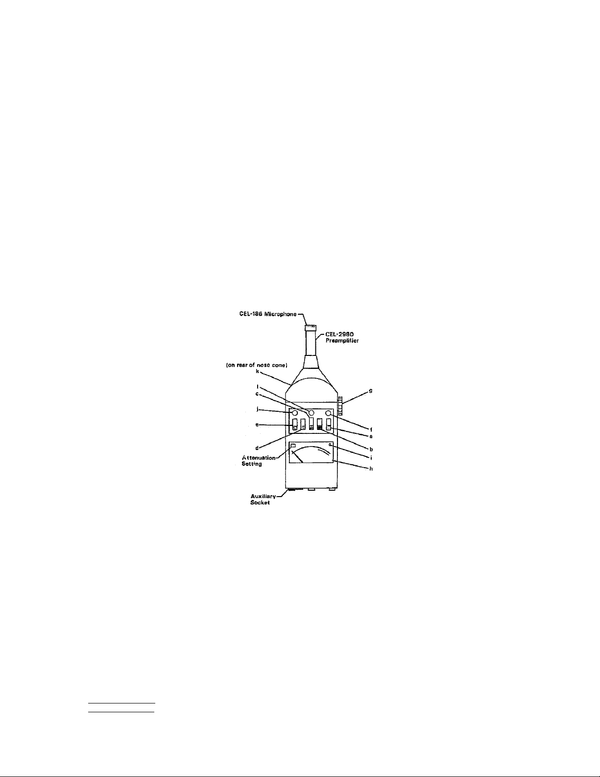
Figure 1
2.2 Controls and Indicators
This section gives a general' description of the functions of the various controls and will enable those
unfamiliar with acoustic instrumentation to quickly establish the correct operational procedures.
(a) ON/OFF
In the OFF position, no functions are performed and there is no drain on the instrument batteries. In the
BATT position the charge state of the lower of the two batteries is indicated on the meter and as long as it
indicates within the scale band marked 'Batt' there is sufficient power to operate the instrument to
specification. When in the ON position, the instrument carries out its selected functions.
/SPL/MAX
(b) L
eq
The answer to be displayed on the meter is chosen by the setting of this control. In the SPL position the
varying sound level is displayed. When the Leq setting is selected the value accumulated since reset for
either equivalent continuous sound level, Leq, the single event noise exposure level LAX, or the ‘takt
maximum' value, LTm, as selected by switch 'e', is displayed.
info@casellausa.com Page 5 of 20 Tel: (800) 366-2966
www.casellausa.com
2 Mar 2009 Fax: (603) 672-8053

Casella USA
17 Old Nashua Rd #15
Amherst, NH 03031 USA
In order to read the maximum value logged during the measurement sequence, the MAX position should be
selected.
(c) PEAK/IMP/FAST/SLOW
This control selects the time constant employed in the RMS detector. The Fast, Slow and Impulse
settings are as required by the relevant National and International Standards. In addition, a 'peak' time
constant is also provided for use in conjunction with the maximum hold mode.
(d) LIN/A/FILTER
The frequency weightings are selected by means of this control. In the LIN (Flat) position the instrument
responds equally to all frequencies within the range 2Hz to 30kHz. The A position introduces the A
frequency characteristic as defined in the precision grade standard thereby giving results in dB(A). When
the EXT position is selected the frequency response is as selected by any suitable network that may be
connected between the filter in and filter out pins on the base of the instrument. The CEL-178 Octave Filter
has been specifically developed for use with the instrument and will provide 10 octave bands plus the
standard A, B, C, D and LIN (Flat) networks. For more detailed analysis the CEL-196 Automatic Third Octave
Analyser is available and full information on both these units is given in separate handbooks.
(e) L
Tm/Leq/LAX
The integral parameter calculated is selected by means of this switch. When the Leq position is selected the
conventional equivalent continuous level is calculated as per ISO and British Standards by integrating the
RMS level. The LTm position selects a mode which causes the maximum RMS value that occurred in a 5
second period to be taken and integrated for the ensuing 5 second period to provide an impulsive weighting
to the result. Alternatively, a 3 second period may be selected by means of the switch located above the
battery compartment (earlier production units were manufacturer pre-set to either 3 or 5 seconds). The
answers obtained in this mode are therefore in line with DIN 45641. Selection of the LAX setting reverts to
conventional Leq operation but the time counter is fixed at 1 second as required by the LAX formula.
Detailed operational notes are given in the latter sections of this manual.
(f) RESET
When pressed this button will cause the noise dose, elapsed time and maximum level stores to be returned
to zero. It also resets the overload indicator. To prevent accidental resets it only operates when the
Leq/SPL/MAX switch (b) is in either the Leq or MAX positions.
(g) ATTENUATOR
This control is located on the right-hand side of the case and is the rotary range change switch. It selects
the measurement range which is indicated in the window on the left-hand side of the scale pan. The
measured value, therefore, is always this value plus the meter reading (plus an additional 30dB if the range
expander button (I) is depressed). When rotated clockwise it increases the level of sound that the
instrument will measure in 10 dB-steps.
(h) METER
Displays the answer as selected on the controls described above. In order that average values can be
displayed at 0 on the scale the instrument's dynamic range is set at -5dB, +55dB relative to scale zero.
(I) OL Indicator
This illuminates when the instrument's circuits are overloaded and hence a wrong answer is being
indicated. It is triggered from both sides of the frequency correction and hence the instrument's range may
be changed during frequency analysis operation. On SPL the overload indicator is illuminated during the
period of overload only;
info@casellausa.com Page 6 of 20 Tel: (800) 366-2966
www.casellausa.com
2 Mar 2009 Fax: (603) 672-8053
 Loading...