

Casella CEL CEL-181 User Manual
Casella USA
17 Old Nashua Road #15
Amherst, NH 03031-2839
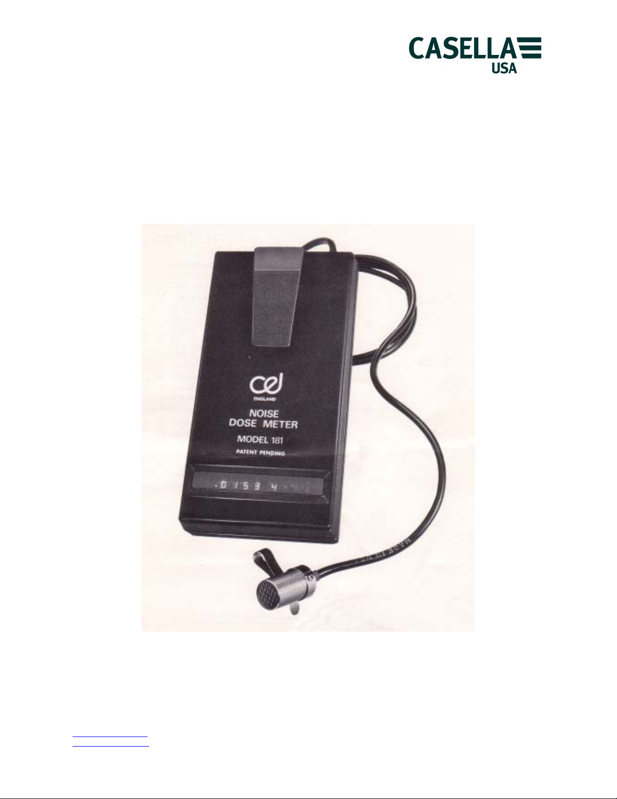
CEL-181
Personal Noise Dosimeter
Handbook
www.casellausa.com Page 1 of 14 tel: (800) 366-2966
info@casellausa.com
27 Jan 2006 fax: (603) 672-8053

Casella USA
17 Old Nashua Road #15
Amherst, NH 03031-2839
CONTENTS
Introduction 2
1 The Risk of Industrial Deafness 3
2 Technical Description 5
3 Operating the Instruments 6
3.1 Dosimeter Calibrator Type CEL-182 6
3.2 Noise Dose Meter CEL-180/181 6
3.2.1 Schedule of Parts 6
3.2.2 Controls and Indicators 7
3.2.3 Connection of the Batteries 8
3.2.4 Calibration Checks 8
4 Measurement Methods 9
5 Analysis of Results 11
6 Care and Maintenance Procedures 11
7 Manufacturer's Warranty and Service Arrangements 12
8 Specification 13
9 Calibration Certificate 14
10 Modifications and Post Production Developments 14
Introduction
These are personal integrating noise dose
meters that have been specifically developed for
the accurate and reliable assessment of the
degree of auditory hazard associated with any
given job function. The design concept allows
for a wide degree of flexibility in determining the
integration law and, hence, they can be preset
to conform to any of the damage risk criteria that
are currently in use. This is achieved by using a
wide range RMS detector followed by an
amplitude-weighting network and in both of
these circuits the main parameters may be
manufacturer preset. Particular attention has
been paid in the design to minimizing the
instrument's weight and physical dimensions in
order that it will be socially acceptable to the
subject and cause minimum interference with
the normal working routine. Special procedures
are employed to ensure the security of the
results, thereby preventing unauthorized access
to the accumulated data.
When worn by the subject the dose meter will
monitor the actual noise level to which he has
been exposed and calculate the percentage of
permitted exposure consumed in accordance
with the procedures laid down in the various
National Standards and Government control
orders that apply in each individual country.
When calibrated with a 5dB exchange rate (q =
5) the instruments comply to the OSHA
regulations published in the United States and
with q = 3 they comply with the International
Standard ISO R1999. Furthermore, the impulse
time constant may be, employed as required by
certain West German regulations. Each of these
calibration settings is clearly explained in this
manual and each instruments' calibration is
indicated by a letter code on the serial number
plate. An additional measurement range is
included in the CEL personal dose meter
enabling its range of applications to be extended
to cover measurements in both work areas
having lower noise levels and to undertake
certain environmental noise measurements.
Full details regarding the theory and practice of
industrial noise dose measurements are given in
the latter sections of this manual.
www.casellausa.com
info@casellausa.com
Page 2 of 14 tel: (800) 366-2966
27 Jan 2006 fax: (603) 672-8053
Casella USA
17 Old Nashua Road #15
Amherst, NH 03031-2839
1 The Risk of Industrial Deafness
It has been known for many years that people
employed in noisy occupations invariably
suffered from deafness. Only in recent years,
however, has the full extent of the hazard been
appreciated with the realization that the effects
of excessive noise exposure are non-reversible
but preventable.
The efficiency of the human ear, along with the
other body functions, naturally decreases with
advancing years. However, this effect known as
presbycusis would not, in general, leave an
individual with a 'social handicap' in later life. It
would not cause any problems with everyday
conversation or limit their ability to work or enjoy
a full social life. In addition to this natural
deterioration, however, will be added other
losses in hearing acuity resulting from disease,
accidents or excessive noise exposure, which
could well result in a total degree of deafness
that would present a considerable social
handicap quite early in life.
Within the ear is a very clever, yet delicate,
system that enables us to hear. A diaphragm
in these cases. The only 'cure' for industrial
deafness is, therefore, prevention-Hearing
Conservation.
In order to fully understand the subject an
extensive research campaign was directed
towards establishing exactly how much noise
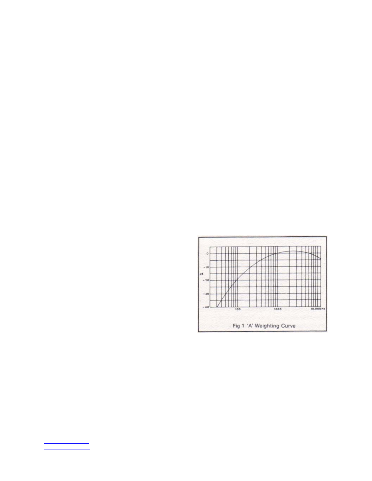
caused a given degree of deafness. Firstly, it
was established that certain frequencies were
more dangerous than others. To accommodate
this fact a special frequency filter has been
derived for use when the hazard potential of
sound is being assessed, The response of this
filter gives added weight to the more hazardous
frequencies in the range 1-5kHz and
proportionally derates those outside this band
according to a carefully defined formula. This 'A
weighted' response, as it is known is specified in
all the international and national standards
relating to the assessment of deafness risk that
are known to date. 'A weighting' is, therefore,
built into all CEL personal noise dose meters
and it is not necessary to make any further
separate measurements of frequency when
using these instruments to measure auditory
hazards.
(the tympanic membrane) converts the air
pressure fluctuations that constitute sound into a
mechanical motion. This motion is then
transmitted through the middle ear, with some
mechanical advantage by a system of small
bones (the ossicles), to the inner ear, Here, the
mechanical movement is converted into nerve
impulses by the cochlea which are then
transmitted to the brain, for interpretation, by the
eighth nerve. Sudden very high intensity sounds,
such as those associated with explosions, can
cause a rupture of the tympanic membrane and,
in severe cases, a disruption of the auditory
ossicles. Such dramatic effects are not,
however, as serious as would first appear. Many
eardrums wiII, in fact, heal themselves and,
thanks to modern medical and surgical methods,
many types of malfunction of the outer and
middle ear can be rectified. Far more serious
damage will result from prolonged exposure to
much lower levels. Continued exposure to even
only moderately intense sounds will result in a
permanent reduction in the ability of the cochlea
to produce nerve impulses for transmission to
the brain and, because of its nature and
location, treatment for a noise-damaged cochlea
is just not possible. As nerve signals to the brain
are not being generated, amplification of the
sounds by a hearing aid would be of little benefit
www.casellausa.com Page 3 of 14 tel: (800) 366-2966
info@casellausa.com
27 Jan 2006 fax: (603) 672-8053
The other parameter of risk was established as
the total noise immission which is proportional to
the measured noise level in dB (A) and the
duration of exposure, Results of large scale
investigation of noise exposed workers that
compared their total noise immission with the
degree of deafness acquired has shown that if
noise immission is contained to around 90dB(A)
for an eight hour working day they should not
acquire a degree of deafness that would
constitute a social handicap after a working
lifetime. As the noise level is increased so the
Figure 1
Casella USA
17 Old Nashua Road #15
Amherst, NH 03031-2839
exposure duration must be reduced in order to
contain the total noise immission or ‘noise dose'.
One of the main variables found between
different noise control regulations is the
relationship between noise level and exposure
time. The International Standards Organization
followed by most European countries favor an
'equal energy' concept where the exposure
duration is halved for each 3dB increment in
noise level (q = 3) whilst in North America the
'exchange rate' calls for a halving of exposure
for each 5dB increment in noise level (q = 5). At
other times regulations calling for q = 4 and q =
6 have been noted.
The problem that arises in actual industrial
situations is that the noise level is never a
constant level to compare against the criteria but
it is continually changing as machines come on
and off load, pressures are vented and
processes move through various phases. It is
necessary, therefore, to continually monitor the
noise climate and process the results such that
the total noise is accumulated in the correct
manner in order to provide a noise dose figure
for comparison against the damage risk criteria.
Therefore, noise dose is proportional to the time
integral of the instantaneous level that is
amplitude weighted and referred to a criterion
level. A constant factor is added to scale the
results in terms of exposure and to provide an
answer of 100 for one daily dose enabling
results to be expressed as a percentage of
permitted exposure.
The basic criteria discussed above are accepted
in most countries of the world; however, as an
added complication some have advanced
further than others with their noise control
programmes and have been able to reduce the
criterion in order to give a better safety margin in
respect of the more noise susceptible subjects.
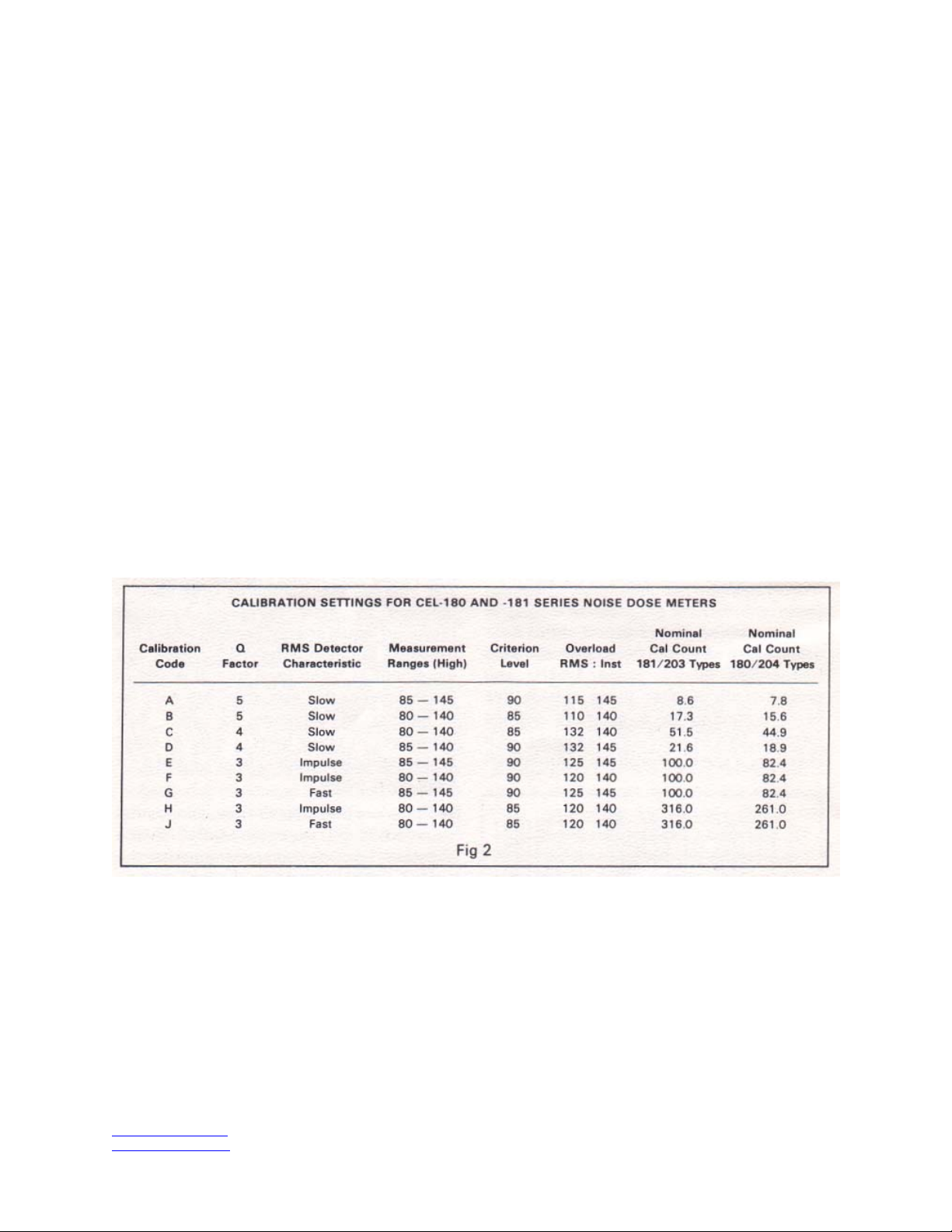
In order to accommodate these requirements all
CEL personal noise dose meters are available
having their criterion levels set accordingly;
these calibration settings are also manufacturer
preset. The various settings are indicated by a
letter code on the serial number plate and a
complete schedule is set out below:
Figure 2
www.casellausa.com Page 4 of 14 tel: (800) 366-2966
info@casellausa.com
27 Jan 2006 fax: (603) 672-8053
Casella USA
17 Old Nashua Road #15
Amherst, NH 03031-2839
2 Technical Description
The CEL-180 meets all the essential requirements for Precision Sound Level Meters. These
are defined in the International Standard IEC
651 type 1 (IEC 179) and the British Standard
BS 4197. As this instrument conforms to the
highest standard of accuracy it is no longer
necessary to make any special provision for
possible instrumentation errors when applying it
to industrial situations. The CEL-181 meets the
lower accuracy requirements outlined in the
relevant sections of IEC 651 type 2, BS 3489
and ANSI S1.4
The microphones employed in the CEL-180
Noise Dose Meters are half-inch (12.7mm)
Precision Measurement Microphones type
CEL-186. These microphones have extremely
uniform frequency response and very high
calibration stability. The signal from the
microphone is passed to the main unit over
approximately 0.5m of cable where they are
amplified and applied to an 'A' frequency
network. The CEL-181 types have similar
configuration but employ a 12mm piezo-electric
type of microphone.
A wide dynamic range RMS detector is used in
the device and this feeds a separate amplitude
weighting circuit. The device has, therefore, a
very wide degree of flexibility in its specification
allowing the dynamic range; count rate, q factor
and RMS time constant to be specified within
wide limits. Basically, the RMS detector has a
range of 40dB plus a 23dB crest factor giving a
total input range of 63dB, whist the voltage to
frequency converter can handle a ratio of
10,000:1 (213). The converter can, therefore,
handle the full 40dB RMS level in the q3 mode
as this signal will obviously double in
significance 13 times (40/3). In the q4, q5 or q6
modes the significance of the signal becomes
much less severe with increasing amplitude;
when q = 6, for example, we only have 6.6
doublings so it is only in the q3 case that we
have to consider the voltage to frequency
converter as a possible limitation. The RMS
detector will, however, control all modes of the
instrument and, as mentioned before, this will
handle levels over the range of 40dB with an
additional 23 dB for impulses. To protect against
incorrect answers being given, the instruments
employ a dual overload indication system. The
overload indicator will be set by either an
instantaneous level 63dB up on the threshold or
by an RMS level that is 40dB up. These
overload indication levels can be reduced to
lower levels if required, e.g. to conform to the
USA OSHA regulation the RMS overload level
should be set at 115dB(A) slow.
The active circuit elements are mounted on
glass fiber double-sided printed circuit panels
and extensive use is made of integrated circuits.
The assembly is contained within a high impact
ABS case that has neoprene surface treatment.
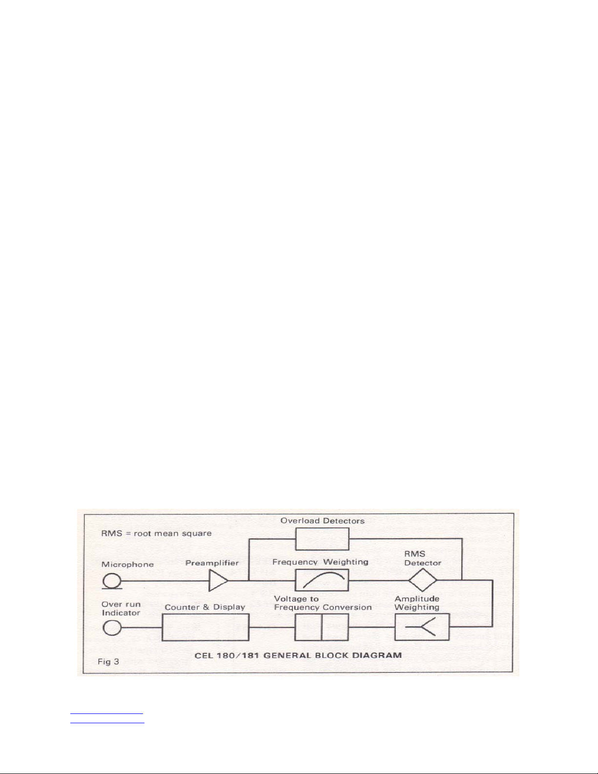
A general block diagram of the instrument is
shown in Fig 3. The various versions have
similar layout of the main circuit elements and
differ only in detail. This diagram is provided for
general information only - for full technical and
servicing information reference should be made
to the service manual.
Figure 3
www.casellausa.com Page 5 of 14 tel: (800) 366-2966
info@casellausa.com
27 Jan 2006 fax: (603) 672-8053
 Loading...