

Casella CEL CEL-160 User Manual

CEL-160 - GRAPHIC RECORDER
Operator's Handbook
Avec les instructions résumes en Français
for
archive Document
Discontinued Instrument
060019
Issue: AD
2/2001
CONTENTS
1. Introduction ........................... 4
2. Commissioning ......................... 4
2.1 Schedule of Parts ...................... 4
2.2 Preparing the Instrument for Service .............. 5
2.2.1 Batteries ......................... 5
2.2.2 CEL-3732 AC Adaptor and Battery Charger ............ 5
2.2.3 Loading the Chart Rolls ................... 5
2.2.4 Input Signals ....................... 5
2.2.5 Routine Maintenance .................... 5
3. Shortform Instructions ...................... 6
3.1 Controls and Indicators .................... 6
3.2 Connectors ........................ 8
3.3 Scale Annotations ...................... 9
3.3.1AmplitudeAxis(Y) ..................... 9
3.3.2TimeAxis(X)........................ 9
3.3.3 Frequency Axis (Y) .....................10
Page 2 - CEL-160 Graphic Recorder
Page
4. Signal Inputs .......................... 10
4.1 Use with the CEL-2980 Preamplifier .............. 10
4.2 DC Inputs ......................... 11
4.3 ACInputs......................... 12
5. Modes of Operation ....................... 12
5.1 Recording of Sound Pressure ................. 12
5.2 Recording of Vibration .................... 12
5.3 RMS Level Recording .................... 13
5.4 Waveform Recording .................... 13
5.5 Recording DC Levels .................... 13
6. Operation with Frequency Analysers ................. 13
6.1 Stepped Serial Analysers ................... 14
6.2 Real Time Analysers ..................... 15
6.3 Continually Variable Narrow Band Analysers ........... 15
7. Additional Instructions for Program Level 2 Instruments ......... 15
7.1 Expanded Trace Recording .................. 15
7.2 Transient Capture ...................... 15
8. Manufacturers Servicing and Warranty Arrangements .......... 18
9. CEL-160 Post-Production Software Amendment ............ 18
9.1 PSS, Preset Start & Stop Bands ................ 19
9.2 VSD, Variable Setting Delay .................. 19
10. Options and Modifications Schedule ................. 19
10.1 Additional Power Supply for Preamplifier ............ 19
10.2 Additional Instructions for Use With B & K 1621 Tunable Band Pass Filter20
10.2.1General .......................... 20
10.2.2Connections ........................ 20
10.2.3Operation ......................... 20
10.2.4Calibration Considerations With Alternative Signal Inputs ...... 20
10.2.5Limitations of Use ..................... 21
10.3 CEL-160/2A Integration Software Options (L
Option) ....... 21
eq
10.3.1Introduction ........................ 21
10.3.2Operation ......................... 22
10.4 CEL-160/2B Reverberation Time (RT60) Measurement Option .... 22
10.4.1Introduction ........................ 22
10.4.2Operation ......................... 23
10.4.3Filters .......................... 23
10.4.4Decay Times ........................ 23
10.4.5Repeat Scans ....................... 24
10.4.6Excitation mode ...................... 24
10.4.7Measurement Day ..................... 24
10.4.8Initiation ......................... 24
10.4.9Summary ......................... 24
10.4.10 Control Signals for Alternative Noise Sources .......... 24
CEL-160 Graphic Recorder - Page 3
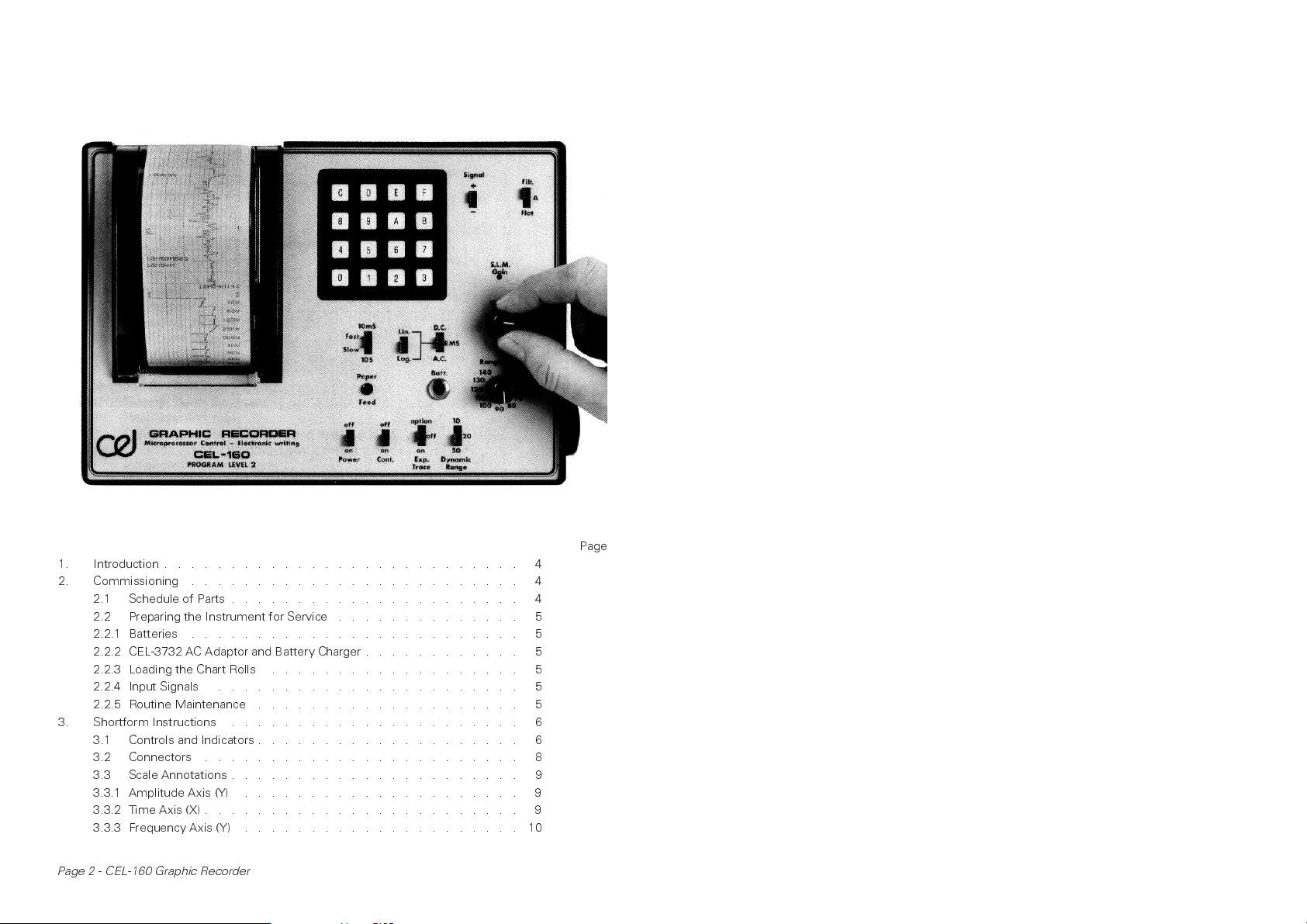
1. Introduction
The CEL-160 represents a completely new
concept in instrumentation for the
measurement of sound and vibration. It
enhances the latest techniques to provide the
most convenient system for documenting
results.
An all-electronic writing system is
employed and hence there are no moving
parts to limit the writing speed. In practice, the
CEL-160 can accurately write levels which
have time constants as short as 10 Ms and
print actual waveforms up to 10 kHz. The
complete system is microprocessor controlled
and is programmed to print its own
measurement graticule as it records; full trace
annotation is provided allowing the time axis to
be read directly without the need for complex
measurement and calculation based upon
chart length. Inputs may be AC or DC signals
and these may be recorded as either
waveforms or levels with the RMS detector
having its time constant selected as either
10 mS, 125 mS (F), 1 S (S) or 10 S and its
output in either linear or logarithmic units. The
software provides for operation with a wide
range of serial and real time frequency
analyzers with; in the former case, a
subroutine that optimises the 'bandwidth-time
constant' product and in the latter full
alphanumeric annotation of each band level.
CEL-160 Graphic Recorders are available
in two basic hardware configurations that allow
for increasing data storage and higher levels of
programming. In addition to the facilities
provided by the basic unit as described above
the 'Program Level 2' option has the capacity
to operate in an expanded trace mode when
making RMS recording or in a transient capture
mode when making waveform recordings. It
also has provision for one customer specified
program package a few of which could be:
calculation of reverbration times (RT
calculation of period L
hearing protector attenuation.
The CEL-160 incorporates a full
specification sound level meter to IEC 651
Type 1 (BS 6959 Type 1, ANSI S1.4 Type 1 and
DIN 45 633) and it is only necessary to add a
CEL-2980 preamplifier, connecting cable and
transducer to be able to make direct
recordings.
or estimation of
eq
),
60
2. Commissioning
2.1 Schedule of Parts
The description CEL-160 Graphic Recorder
complete refers to the following items and on
receipt, the instrument should be checked
against this schedule. Items supplied are
common to both versions.
CEL-160
RS 591-231
CEL-3730
RS-1
CEL-3843
060019
CEL-3876
In addition to the standard items listed above,
there are a number of optional items and
although provision for some of these is made
in the standard transit pack they are only
provided if specifically requested. Such items
will be detailed separately on invoices and
advice notes. The most popular of these items
are as follows.
Accessories
CEL-3729
CEL-3731
CEL-3732
CEL-2980
CEL-186/2F
CEL-3686/2
CEL-2962
CT-3
CEL-3025
Ancillary Instruments
CEL-177 Precision Acoustic Calibrator
CEL-196 Automatic Third Octave
CEL-3789 Ever Ready Case for CEL-196
Graphic Recorder
Battery Pack (set of five alkaline
manganese C cells)
Pack of nine rolls of chart paper
Screwdriver
Writing comb brush
Handbook
Rule
Ever Ready Carrying Case for
CEL-160
Rechargeable Battery Pack
(NiCad)
AC Adaptor and Battery Charger
Preamplifier
Precision Measurement
Microphone
Cable CEL-2980 to CEL-160 -
2 metres
Windshield for CEL-186/2
Tripod (accepts CEL-2980
Preamplifier)
Vibration Adaption Kit
(comprises accelerometer and
mounting kit, connection
cable, passive integrator and
slide rule).
Analyser
(fits to CEL-3729)
Page 4 - CEL-160 Graphic Recorder
The CEL-160 Level 2 is also provided as a
complete sound and vibration measuring and
analysing kit under the part number
CEL-160/K1. This comprises all the items listed
above including the CEL-196 and its associated
connection cables.
2.2 Preparing the Instrument for Service
2.2.1 Batteries
The batteries must be inserted into the battery
compartment that is located on the right hand
side of the instrument with the positive
connection outwards. Having inserted all five
cells with the same polarity the battery cover
should be replaced. If the alkaline manganese
batteries are being used the instrument is
ready for operation. However, it must be
remembered that the NiCad cells are delivered
having residual charge only and they should
therefore be charged before using the
CEL-160 (See section 2.2.2). It is advisable to
remove batteries from the recorder if it is to be
stored for any period of time.
The preferred batteries are the
CEL-3731 NiCad cells. If the RS 591-231 cells
are used there are certain operation limitations.
The internal resistance of the alkaline
manganese cells will not accommodate the
high start up current required at high paper
speeds and will cause deregulation of the
power supplies.
This would be most noticeable on the
transient capture and RTA modes; however,
for most general purpose applications it is
possible to take advantage of the lower cost of
the alkaline batteries.
2.2.2 CEL-3732 AC Adaptor and Battery
Charger
This should be connected to the 220-240 V,
50 Hz mains supply and connected to the
socket on the recorder marked 'power' using
the cable provided that is marked 'voltage'. As
this cable is connected the internal batteries
are disconnected. To operate the CEL-160
from the mains no further connection is
necessary. When it is required to charge the
internal batteries the CEL-160 should be
switched off and the charger connected to the
recorder with the cable marked 'current'. Note
that the alkaline manganese cells must not be
used in conjunction with the CEL-3732
charging unit.
A fully discharged set of NiCad batteries
will take in the order of 12 hours to recharge;
the charger unit is fully regulated and it is not
possible to damage the cells by overcharging.
The front panel indicator fitted to the charger is
provided for charging indication only, and will
remain unlit when operating the recorder with
the 'voltage' cable. To operate the CEL-3732
on 100 - 120V, 60Hz mains supplies the
voltage tap on the transformer primary should
be reset following the instructions marked on
the transformer fitted to the unit.
2.2.3 Loading the Chart Rolls
Chart rolls locate in the compartment on the
top face of the recorder. When opening this
compartment care must be taken to ensure
that the writing comb disengages from the
rubber drive roller.
This is achieved by pressing the front of
the plastic cover towards the back of the
instrument and raising it a few degrees until
the bias springs allow it to move forward
again; it may then be simply hinged open. The
chart roll may now be placed in the tray with a
short section unrolled and placed over the
drive roller, the cover may then be closed
following the reverse procedure ensuring that
the chart is squarely located between the
writing comb and the drive roller. Chart rolls
are supplied by CEL in packs of nine under the
part number CEL-3730.
2.2.4 Input Signals
The CEL-160 is primarily intended for use with
the CEL-2980 preamplifier in conjunction with
the CEL-186/2F microphone, this combination
is connected by means of the CEL-3686 cable.
Alternatively it will accept either
conditioned or unconditioned signals from
sound or vibration level meters. Log DC inputs
may also be connected to the instrument. The
procedures for these modes are outlined in
Section 4 of this manual.
2.2.5 Routine Maintenance
Accepted practices relating to Electronic
Instruments should apply to this equipment
especially in relation to the batteries. From
time to time the debris resulting from the
spark errosion of the chart paper will need to
be removed from the paper tray and also
brushed out of the writing comb. That in the
tray can be dusted out whilst a brush is
CEL-160 Graphic Recorder - Page 5
provided for cleaning the comb. This
procedure needs to be undertaken with care to
ensure that the pins are not damaged and
should always be brushed towards the ends.
With extended use the writing comb will
eventually wear and will need replacing. These
are available under the part number CEL-3842
and are fitted in the following manner.
First the knobs must be removed from
the 'Gain-Cal' and 'dB-Range' controls. This is
achieved by removing their top covers and
releasing the locking collars with a split
screwdriver. It is then possible to remove the
escutcheon plate and some care is needed
here to ensure that it is not bent. It is held in
place by 'low tack' adhesive and the best
approach is to open the chart compartment
and ease away the area around this with a flat
bladed knife. It is easily freed to the left edge
and it is then possible to free it down and
towards the right.
Having removed the escutcheon plate
take care that dust does not settle on the
adhesive face or it can not be refixed. The
paper tear bar (transparent plastic) may now be
pulled out of its locating slots and the two
screws that secure the comb carrier may now
be released (black plastic). These screws are
visible through the two cutouts in the
instruments top plate, a captive or magnetic
screwdriver is recommended to ensure they
are not lost inside the instrument.
Either end of the comb carrier should
then be held and pulled upwards to release the
comb assembly from its 100-way connector.
The comb (light blue plastic) may then be
unclipped from its carrier and the replacement
fitted by reversing this procedure. New combs
will require to be 'run in' for a short period
before an even burn is obtained, this is best
achieved by running the unit at 10 mm/S in the
AC mode with a full scale deflection input for
about 5 minutes.
3. Shortform Instructions
These instruments are, by definition, complex
devices and it is not, therefore, possible to
give definitive shortform instructions.
However, those who are familair with
advanced acoustic and digital instrumentation
will be able to gain an appreciation of the
operation of the instrument from the
description of the functions of the various
controls and indicators given in the following
section.
3.1 Controls and Indicators
The functions of the various controls are
described below. They are identified by the
legend that appears on the instrument's panel
and may be located by working from left to
right starting with the bottom row.
Power. on-off
This is the main power switch and controls the
instrument on both mains and battery
operation. When in the ON position the
instrument carries out its selected function
whilst in the OFF setting no power is drawn
and no functions are carried out, apart from
battery charging.
Cont. on-off
This switch controls the power supplies to the
paper transport and writing systems. In the
OFF position all the measurement and
processing functions are operational but paper
transport is inhibited, this arrangement allows
for the correct setting up of a measurement
system without wasting chart paper.
Exp. trace. on-off-option
(Not fitted in Program Level 1 versions)
In the expanded trace setting, the instrument
operates in either the expanded trace or
transient capture modes depending on the
setting of the AC-RMS-DC switch. The
OPTION position selects one of the customer
specified options that may be programmed
into the instrument, where an option is
provided its functions are fully detailed in the
section at the end of this manual.
Dynamic Range. 10-20-50
Sets the dynamic range of the print-out in dB.
It is only operational in the RMS mode.
Range (dB)
Sets the full scale deflection value of the trace
when the instrument is operating in the sound
level mode with the CEL-2980 preamplifier. It
also controls the sensitivity of the auxiliary AC
input but over a narrower range, reference
should be made to Section 4.3 of this manual.
Gain-CAL
This is a continuously variable analogue control
that sets the gain of the DC amplifier, and it is
Page 6 - CEL-160 Graphic Recorder
in series with the main attenuator switch
described above. When the instrument is
being used in the AC or RMS modes it should
be set to the CAL position. In the DC mode it
will set the sensitivity in terms of mV/dB and in
this mode of operation the main attenuator
switch (RANGE dB) is not in circuit.
S.L.M. Gain
This control is also in series with the main
attenuator switch and is used to trim the gain
of the AC amplifiers to take account of
differing microphone sensitivities. Full
description is given in the sections dealing
with sound level meter calibration (4.1).
Batt.
The voltage of the internal batteries are
indicated by this meter. As long as it remains
within the scale banded green there is
sufficient power to operate the instrument to
specification.
Contrast
The burn voltage to the writing comb is set by
this control and it can therefor be used to take
out any slight variation in the print contrast
obtained between different batches of
recording paper.
Paper Feed
Feeding of blank paper through the writing
comb is achieved by depressing this button.
10S-10mS
This control sets the averaging time of the
RMS detector and is only operational in the
RMS mode. The fast and slow settings provide
the standardised time constants of 125 mS
and 1 S respectively as defined in the sound
level meter standards.
Lin-Log
The output of the RMS detector is selected as
being either linear in terms of dB (log mode) or
mV (lin mode) and again this control only
operates in the RMS mode.
A.C.-RMS-D.C.
In the AC mode the input signal is fed direct to
the writing head hence allowing the
instrument to operate in the waveform mode.
The RMS setting sends the signal via the RMS
detector to provide operation in the level mode
whilst a similar mode of operation is provided
in the DC setting for DC input signals only. It
must be remembered that in the DC mode the
input must be in terms of mV/dB (i.e. voltage
linear in dB) for correctly scaled results.
Lin-A-Filter (or Flat-A-Filter)
This control routes the AC input signals either
direct to the input amplifier, via the
standardised A weighting filter or diverts the
signal via the filter IN and OUT sockets on the
side panel. In this later mode the instrument
may be used with the CEL-196 Automatic
Third Octave Analyser to provide fully
annotated frequency plots.
Signal +/-
When operating in the DC mode this control
allows for the polarity of an input signal to be
set either -ve or +ve going. 0 V is taken as
0 dB on the 50 dB dynamic range setting.
When the 10 dB or 20 dB dynamic range is
selected in the DC mode it must be noted that
the scale is expanded from full scale deflection
downwards.
Key Pad
This is used for inputting all the main
operational instructions to the instrument.
Each main function is designated one of the
letter codes and this should be preceded by a
number code specifying the exact require-
ment. The main codes are summarised below.
A Sampling ratesfor transient capture mode
(not operational on Program Level 1 version)
0 = 36 µS, 1 = 108 µS, 2 = 360 µS, 3 = 1080 µS,
4 = 3600 µS.
eg for 108 µS sample rate, key 1A. Start up
state 0A.
A second entry of 5 through to 9A will select
the block length for the data sample. See
section 7.2 and Fig 8.
B Paper Speed
0 = one step up in speed 1 = 30 mm/S
2 = 10 mm/S 3 = 3 mm/S
4 = 1 mm/S 5 = 0.3 mm/S
6 = 0.1 mm/S 7 = 0.03 mm/S
8 = 0.01 mm/S 9 = one step down in speed
eg for 10 mm/s, key 2B. Start up state 3B.
C Clock Setting
The clock automatically comes on at zero time
but may be set to real time by keying in the
actual time required on a 24 hour clock
CEL-160 Graphic Recorder - Page 7
followed by a C. (Operation of C key is actual
entry time, eg for 5.53 p.m. key 1753C). Start
up state 00H00M00S. The instrument also has
a 10 day elapsed day counter and this will
increment 1 day as the clock passes 24.00 but
it cannot be preset.
D Preset Scale Annotation
When the instrument is being used with the
integral sound level meter, the annotation on
the top of the paper is the main attenuator
setting whilst that at the bottom is the same
level minus the dynamic range setting. If it is
required to operate in the non SLM mode then
the FSD figure should be entered as a one or
two digit decade followed by D. The minimum
scale deflection will again, be calculated from
the dynamic range setting.
eg for
SLM
180 dB FSD
calibration.
key
180D.
Start up state
E Frequency Analysis Trigger
Operation of this key will initiate the frequency
analysis program. Full details are given in
Section 6 of this manual.
F. Select Frequency Analyser Type
The control logic to operate the following
analysers is pre-programmed into the CEL-160,
however, non-standard packages are available
and if fitted to this unit details are given in
section 12 of this manual.
0 CEL-196 Automatic Third Octave 20 Hz- 20 kHz
1 Rion SA-59 Serial Third Octave 25 Hz-20 kHz
2 Rion SA-59 Serial Third Octave 2.5 Hz-2 kHz 3 Bruel
and Kjaer 1618 Serial Third Octave
4 Bruel and Kjaer 2215 Serial Octave
5 Bruel and Kjaer 1616 Third Octave 25 Hz-40 kHz
6 Bruel and Kjaer 1621 Continually Variable Narrow
Band 20 Hz-20 kHz
7 Bruel and Kjaer 1621 Continually Variable Narrow
Band 2 Hz-2 kHz
8 Rion SA-24 Real Time Third Octave 31.5 Hz-8 kHz
9 Rion SA-24 Real Time Third Octave 1 Hz-250 Hz
eg for Bruel and Kjaer 1616 key 5F. Start up
state 0F.
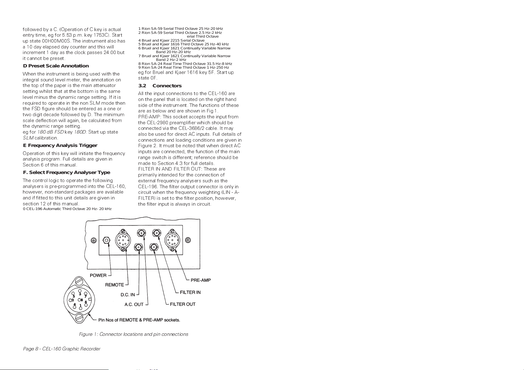
3.2 Connectors
All the input connections to the CEL-160 are
on the panel that is located on the right hand
side of the instrument. The functions of these
are as below and are shown in Fig 1.
PRE-AMP: This socket accepts the input from
the CEL-2980 preamplifier which should be
connected via the CEL-3686/2 cable. It may
also be used for direct AC inputs. Full details of
connections and loading conditions are given in
Figure 2. It must be noted that when direct AC
inputs are connected, the function of the main
range switch is different; reference should be
made to Section 4.3 for full details.
FILTER IN AND FILTER OUT: These are
primarily intended for the connection of
external frequency analysers such as the
CEL-196. The filter output connector is only in
circuit when the frequency weighting (LIN - A-
FILTER) is set to the filter position, however,
the filter input is always in circuit.
Figure 1: Connector locations and pin connections
Page 8 - CEL-160 Graphic Recorder
 Loading...