

Casella CEL Airborne particulate monitoring system User Manual

USER MANUAL
COPYRIGHT
The copyright in this document which contains proprietary information is vested in
CASELLA LIMITED. The contents of this document must not be used for
purposes other than for which it has been supplied or reproduced or disclosed wholly
or in part without the prior written permission of CASELLA LIMITED.
AIRBOURNE PARTICULATE
MONITOR
APM950
CASELLA LIMITED
Regent House Telephone: +44 (0)1234 841441
Wolseley Road Facsimile: +44 (0)1234 841490
Kempston e mail: casella.limited@enterprise.net
Bedford Telex: 827707
MK42 7JY

CONTENTS.
1. Introduction.............................................. 1
2. Principle of Operation.............................. 2
3. Installation................................................ 4
4. Optional Sensors...................................... 11
5. Operation.................................................. 16
6. Maintenance and Servicing...................... 32
7. Fault Finding............................................ 39
8. Calibration................................................ 40
9. Specification............................................. 49
10. Warnings................................................... 51

INTRODUCTION
Airbourne particulate matter can be found in ambient air in the form of dust, smoke, pollen or
other aerosols. Major sources of particulates in the urban environment include industrial
combustion and processing, energy generation, vehicle engine emissions, and construction.
Particulate matter is responsible for reduced visibility, contamination and is also recognised as a
cause of many medical conditions.
The health risks posed by inhaled particulates led the United States Environmental Protection
Agency (E.P.A.) to establish size specific dust monitoring standards. The 'cut points' are refered
to as PM10, PM2.5 and more recently PM1.
The PM10 cut refers to a size selective sampling head having a 50% inlet cut off at an
aerodynamic diameter of 10
affects of particulates on health conditions.
The health and environmental risks presented by airbourne particulates has increased the need
for reliable real time dust measurements. Air quality monitoring networks have been established
to determine compliance with statatory air quality criteria.
µm. PM10 is usually adopted for monitoring studies related to the
Casella’s APM 950 system has been designed to monitor the mass concentration of ambient
airbourne particulates in real time. An integral data logger is used to record a variety of
particulate and meteorological data for the subsequent analysis of contamination trends.
Simultaneous gravimetric sampling provides comparitive analysis with real time data and may
be used to calibrate the system to suit local conditions.
Additional meteorological values including wind speed, direction, temperature and humidity
may also be monitored by the system helping to establish major sources of pollution and long
term trends.
HB3256-03 Page 1

PRINCIPLE OF OPERATION
Please refer to the APM950 schematic drawing.
Ambient dust is drawn into the Total Suspended Particulate (T.S.P.) or size selective PM10
sampling head.
Sample flow is precisely regulated by means of a built in diaphragm pump and electronic control
circuitry. A state-of-the-art mass flow transducer is used to provide flow feedback information,
this ensures a highly reliable and stable flow rate of 16.7L/min is achieved. (Temperature
compensated volumetric flow is available as an option). A ‘flow smoother’ unit reduces the
amplitude of pump pulsations within the air flow.
The sample air passes through a heater assembly where it is warmed to eliminate errors resulting
from suspended moisture droplets and high humidity levels. The sample is raised to typically 2025°C above ambient.
The high sensitivity optical sampling head is based upon the forward scattering effect of an near
infra red beam. The response is optimsed for the measurement of respirable particulates below
10
µm in diameter. Signal processing electronics are used to control the infra red emitter and
provide conditioning of the return signal.
After passing the optical sensing stage, all particulates within the sampled air are collected and
retained on a 47mm filter. Gravimetric results may be correlated to the real time data to provide
optimised calibration accuracy. Additional analysis of filters may be used to establish the
chemical composition of contaminates.
A purge pump maintains a supply of clean dry air to the optically sensitive components within
the probe. The protective air shield protects against particle deposition and ensures reliable long
term operation. It is also used to establish a zero dust level during automatic calibration checks.
A programmable logger and micro controller are used to sequence the overall system operation,
monitor signals and record data. The data saved within its internal memory may be extracted
using a laptop P.C. memory card or remotely via a telephone modem.
HB3256-03 Page 2
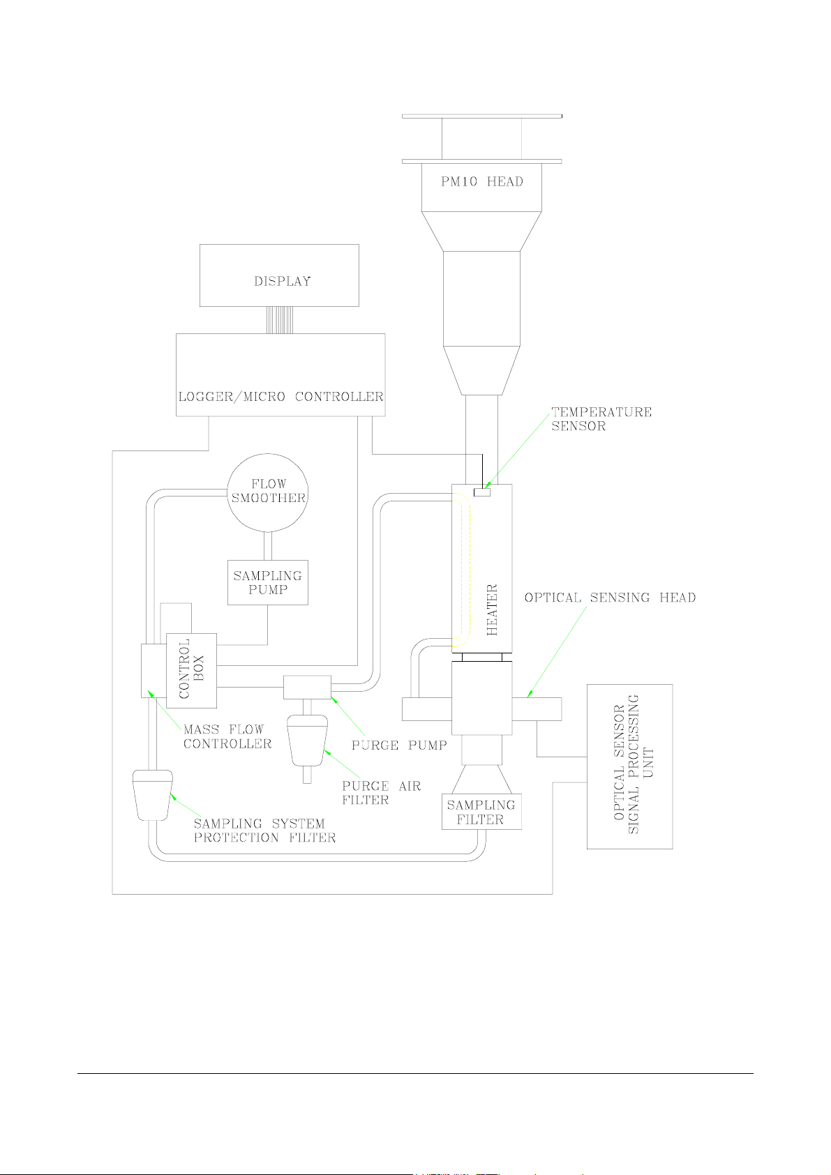
APM950 System Schematic
HB3256-03 Page 3

INSTALLATION.
Warning: BEFORE ATTEMPTING TO ASSEMBLE AND INSTALL THE APM950,
PLEASE CAREFULLY STUDY THE INSTALLATION PROCEDURES AND
DRAWINGS PROVIDED IN THIS MANUAL. FOR SPECIALISED SYSTEMS,
SUPPLEMENTARY ASSEMBLY NOTES MAY ALSO BE PROVIDED.
You should contact your supplier immediately, should any parts be missing or damaged.
Choice of site.
Particular attention should be paid when choosing a suitable site for the APM950 system since
particulate concentrations and meteorological parameters can show significant variations over
small distances. A site should be chosen where the ambient air quality may be considered
representative of the general scene. Avoid locations where the equipment can be influenced by
localised sources of contamination such as ventilation or flue outlets, vehicle emissions or
construction work.
The site should be free from air turbulence caused by trees, buildings, hills etc. It should not be
sheltered or unduly exposed such as on the crest of a steep hill.
It should be noted in particular that a roof does not provide a suitable exposure for an
anemometer unless it is mounted well above the roof.
The cross arm assembly supplied with the wind speed and direction sensor is designed to be
mounted onto a 50mm diameter pole. When setting up the cross arm, the wind vane body should
be set up to point north.
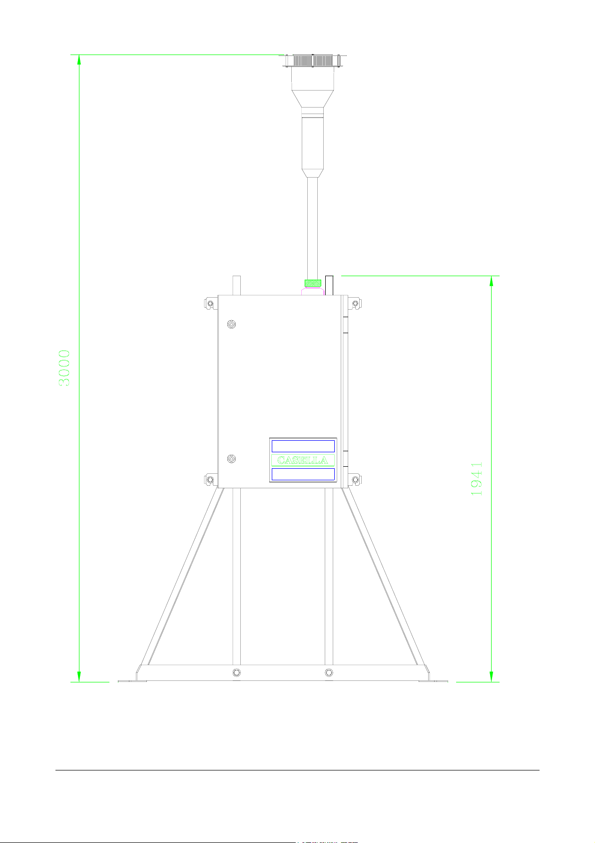
Frame based systems.
For frame mounting applications please refer to the frame assembly drawings. Frame assembly
can be aided by beginning with the two upright sections laying down. The base end of the two
upright sections is denoted by the larger drilled holes. Ensure the correct size fasteners as
indicated on the drawing are used throughout the assembly. The APM950 enclosure can now be
secured to the frame using the correct bolts and washers as shown in the drawing.
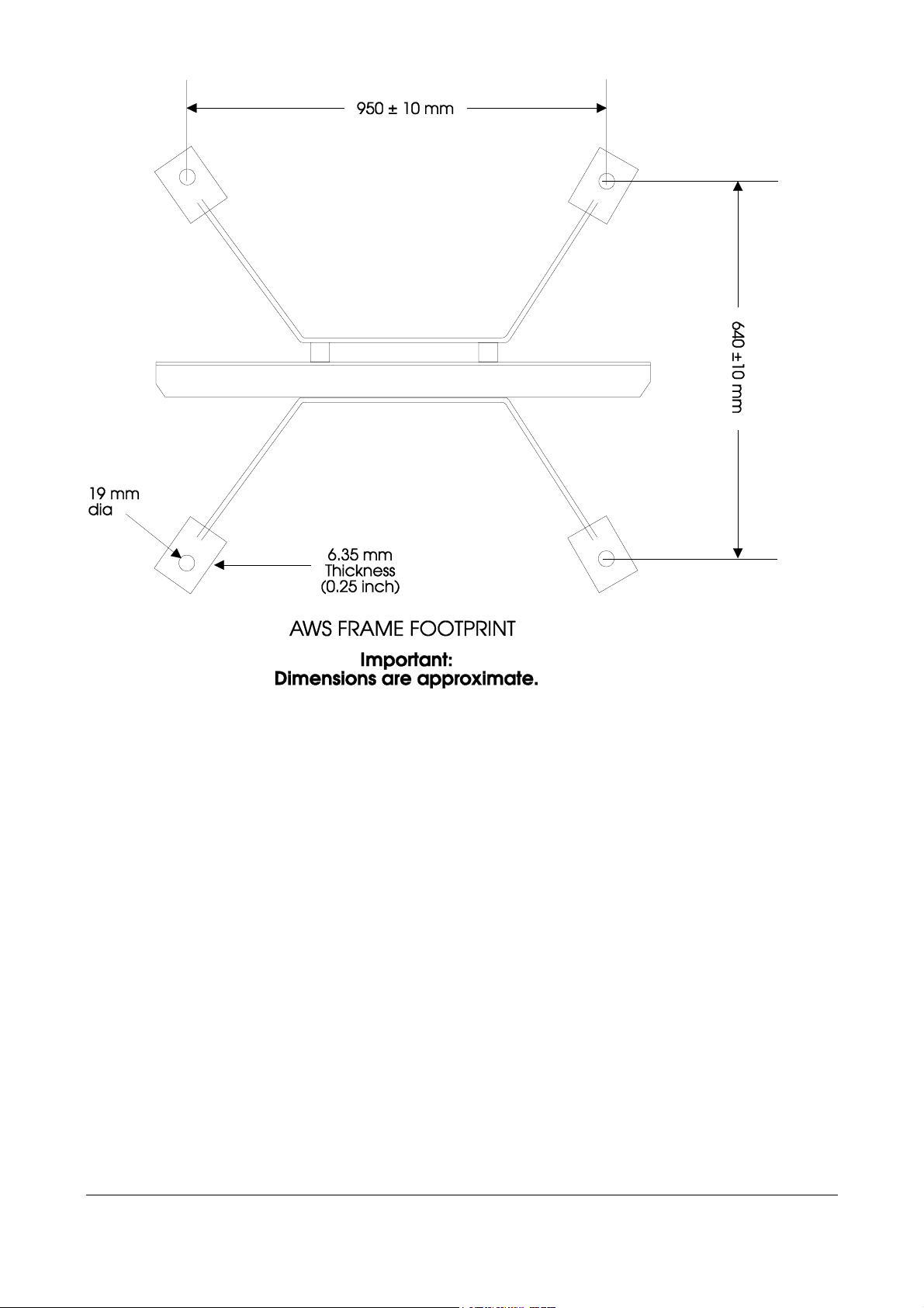
The frame assembly must be securely mounted by its four feet onto a solid surface such as a
purpose made concrete base or roof of a building etc. A typical concrete base would be 1.5
metres square and approximately 20 to 30cm thick. The frame should be vertical and level.
In the majority of applications M8 rawl bolts maybe used to secure the station frame to the
mounting surface (M8 rawl bolts require a 14mm diameter mounting hole). The actual fixing
technique used should pay consideration to the material type, roof structure and material
thickness present at the installation site.
HB3256-03 Page 4

The frame footprint drawing indicates the approximate position of fixing holes. It is suggested
that as a more accurate method the actual frame base should be used as a template when drilling
the mounting holes in the site location.
Wall mounted systems.
For wall mounted applications which will be attached to the inside of a case or shed etc., please
refer to the wall mounted drawings.
It should be noted in particular when choosing a suitable enclosure for mounting of the APM950
that a sloping roof enclosure is not desirable as this will cause variations in the wind dependant
upon the slope of the roof and the direction of the wind.
The APM950 can be supplied with two cross arms for wall mounting the enclosure as shown in
the installation drawings section. These cross arms are attached to APM950 enclosure and then,
using either the pre-drilled holes or holes drilled to your own requirements, the APM950 can be
mounted to the wall of the outer enclosure.
Alternatively, if convenient, the enclosure can be mounted straight on to the wall by using the
mounting brackets of the case. The dimensions of which are shown within the installation
drawings section. It may be wise to use the actual case and brackets as a template to drill the
holes in the wall. Again consideration must be given to the wall material, thickness etc. when
attaching the system to a wall/shed etc.
If this option is undertaken then a hole will need to be placed in the roof of your enclosure for
fitting of the Anderson head. (see the installations drawing section).
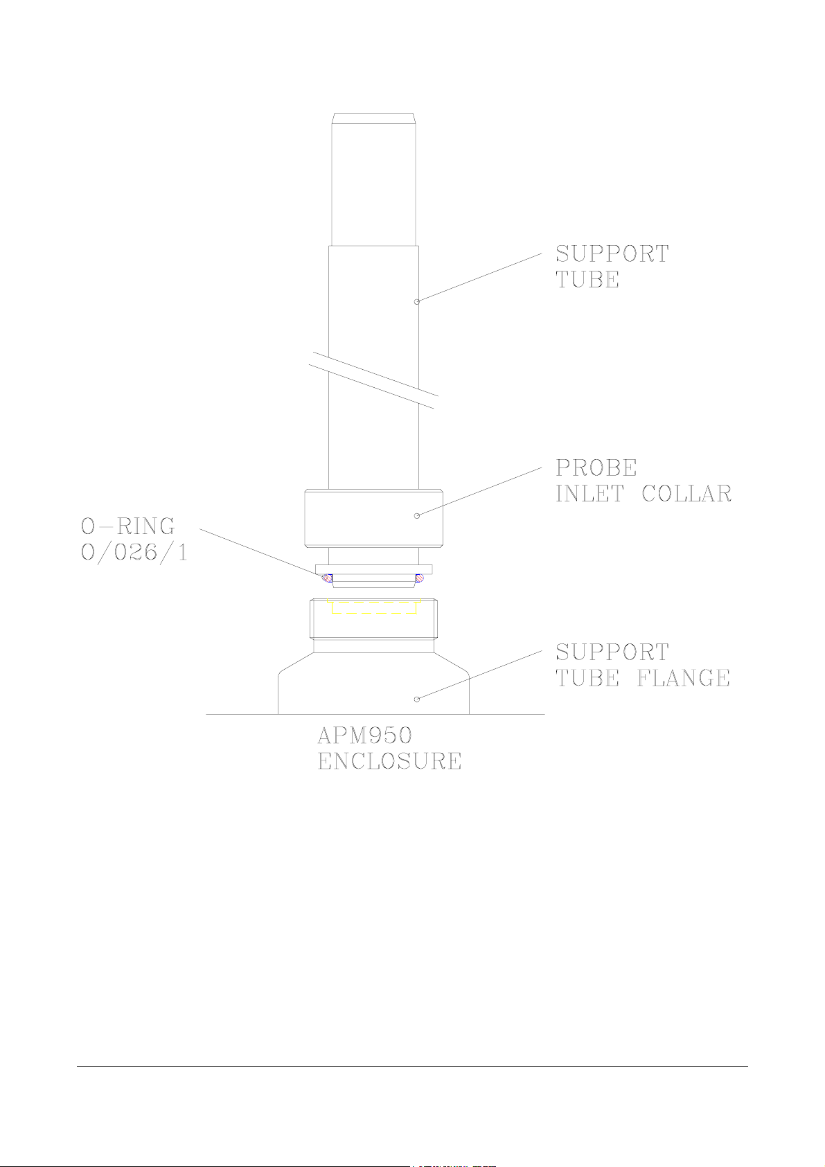
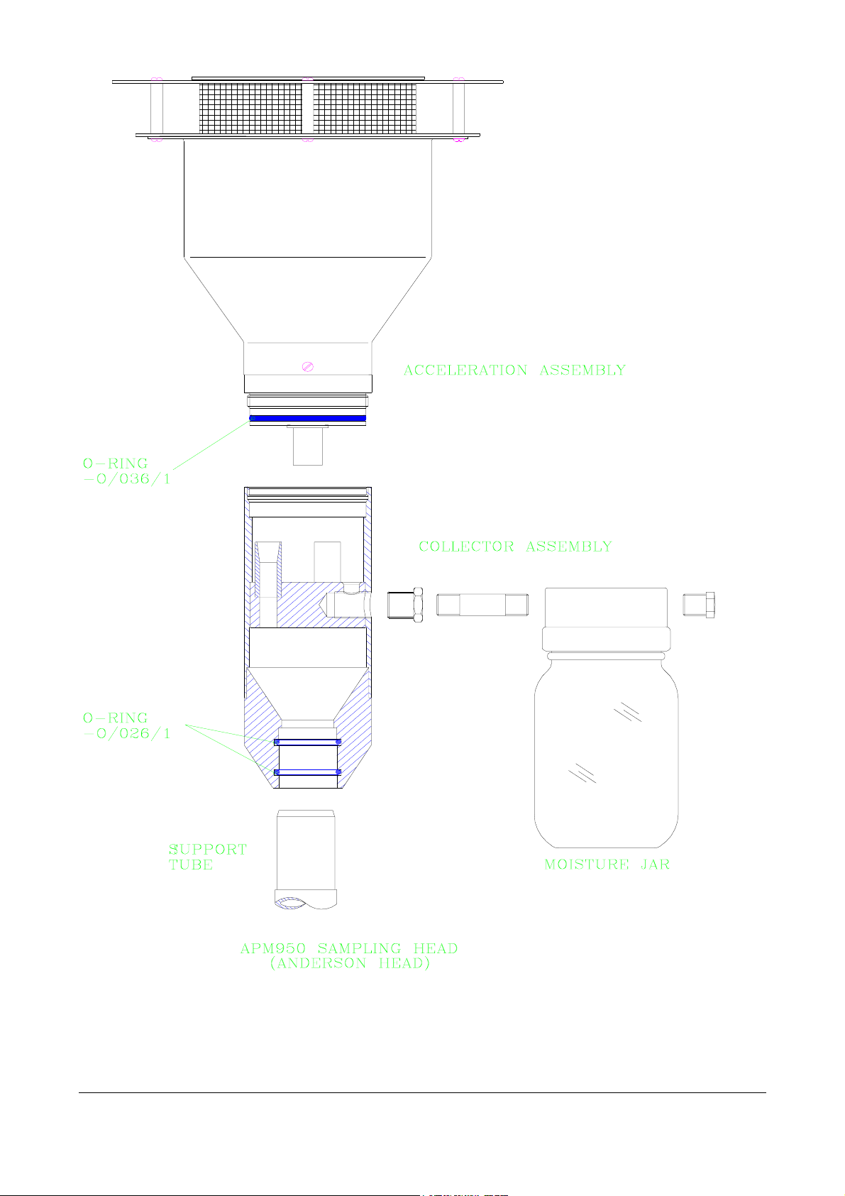
Size Selective Head.
The system is supplied with the head separate. Before assembly check that O-ring 0/026/1 is in
place on the support tube and that the threads have a film of silicone grease. Failure to maintain
an adequate seal may result in air leakage and water ingress.
The assembly is attached simply by removing the transit cap from the support tube flange on the
enclosure and mounting the support tube assembly as shown in the installation drawings section.
The probe inlet collar is then tightened. The moisture jar is assembled to the Anderson head, and
the whole assembly placed onto the support tube as shown.
Roof Inlet.
It is important to maintain a reliable water tight seal between the sample inlet tube and the roof
structure. Failure to maintain a seal will result in water flowing down the inlet tube and into the
building.
HB3256-03 Page 5
HB3256-03 Page 6

System wiring.
Basic system wiring is simple providing the manual is studied carefully and care is taken. Wiring
should only be carried out by qualified personnel who are familiar with the procedures and
precautions necessary when wiring such electronic devices.
Warning: INCORRECT WIRING MAY RESULT IN DAMAGE TO THE SYSTEMS OR
SENSORS. SUCH DAMAGE WILL BE THE CUSTOMERS RESPONSIBILITY AND IS
EXCLUDED FROM THE CONDITIONS OF WARRANTY.
Connection details for additional sensors are shown within the 'Optional Sensors' section of this
manual.
Position each sensor in their final position. Route the cables neatly back to the base of the
enclosure. Loosen and remove the cable gland lock nut. DO NOT REMOVE THE CABLE
GLAND.
Now thread the sensor cables through the enclosure cable entry holes and secure the cable gland
using the lock nut. Ensure the cables pass from the outside to the inside of the enclosure.
Testing the system.
Before apply power to the system, confirm all system wiring is correct.
To confirm operation of the system, it will be necessary to install and initiate the supplied
software, please refer to the software section of this manual for details.
HB3256-03 Page 7
HB3256-03 Page 8
HB3256-03 Page 9
HB3256-03 Page 10

OPTIONAL SENSORS.
Wind Speed
Description
This sensitive anemometer is based upon the three cup rotor design. The instrument is robust
and easy to use, with overall design determined by the extensive use of the Royal College of
Aeronautics (CIT) wind tunnel facilities.
The instrument has been designed and tested to meet the recommendations adopted by the
European Commission CIMO (WMO N272 Brussels 11-22 September 89).
The instrument is constructed using Aluminium alloy, which is then anodised. This results in a
durable all weather construction.
Specification
Transducer Optical interrupter
Maximum design wind speed 75 metres/second
Starting velocity Typically 0.4 metres/second
Distance constant Typically 5.3
Resolution 7.2 cms
Non-Linearity
Accuracy
Calibration 13.8 Hz/metre/second
Pulses per rev 20
Operating temperature range
Storage temperature range
Supply voltage 7-20 volts d.c.
Current consumption Typically 15mA at 12 volts
Output calibration 0 to 5 volt pulses.
Part no. 120800B-03
0.6 % (from 3 to 40 metres/second)
1% above 3 metres/second
-20°C to + 70°C
-50°C to + 70°C
HB3256-03 Page 11

Wind Direction
Description
This sensitive wind vane has been designed and tested to meet the recommendations adopted by
the European Commission CIMO (WMO N272 Brussels 11 - 22 September 1989).
The instrument is constructed using aluminium alloy, which is then anodised. This results in a
durable all weather construction.
Specification
Transducer Continuous rotation wirewound
potentiometer
Maximum design wind speed 75 metres/second
Aligning threshhold 1.2 metres/second @ 10° offset
Distance constant Typically 2.3
Undamped natural wavelength 6.2 metres
Damping ratio 0.35 to 0.45
Repeatability 0.5% f.s.d.
Time constant 0.35 second
Electrical angle 0 - 355° (north between 355° and 0°)
Operating temperature range -20°C to +70°C
Storage temperature range -50°C to +70°C
Supply voltage 7 to 20 volts d.c.
Current consumption Typically 2 to 3mA at 12 volts
Output calibration 0 to 1.8 volts d.c. for 0 - 355° rotation.
Deadband = 0 volts output
Part no. 120804B-04
HB3256-03 Page 12

Combined Temperature &
Relative Humidity
Description
This combination %rh and temperature sensor is mounted within a single radiation screen. Both
transducers are unaffected by condensation and are resilient to airborne pollution. The
hygrometer is of the capacitative type, is largely free from drift and offers high repeatability over
large ranges of humidity for long periods. The temperature sensor is based upon a platinum
resistance element to BS1904, DIN 43760, and incorporates linearisation electronics within the
sensor. The output of the temperature sensor is used to compensate the hygrometer for
temperature effects. This ensures that the combination sensor achieves the maximum
performance for this type of device.
Specifications
Hygrometer
Sensor type Capacitive
Measuring range 0 - 100%rh
Calibrated accuracy
Hysteresis
Time constant 10% to 90% rh <10 seconds
Operating temperature -25°C to +80°C
Temperature
Sensor type Platinum resistance MO 1000RTD thin film
Measuring range -40°C to +60°C
Calibrated accuracy
Operating temperature -40°C to +60°C
General
Part no. 120738B-02
Supply voltage 8 to 24 volts d.c.
Current consumption Typically 10mA at 12 volts
Output calibration Temperature = 0 to 1 volt for -40°C to +60°C
2% between 30 and 80%
1%
0.3°C @0°C, 0.55°C @50°C
Humidity = 0 to 1 volt for 0 to 100%rh
HB3256-03 Page 13

System wiring.
The basic system wiring is simple providing the manual is studied carefully and care is taken.
Wiring should only be carried out by qualified personnel who are familiar with the procedures
and precautions necessary when wiring such electronic devices.
Warning:
INCORRECT WIRING MAY RESULT IN DAMAGE TO THE SYSTEMS OR
SENSORS. SUCH DAMAGE WILL BE THE CUSTOMERS RESPONSIBILITY AND
IS EXCLUDED FROM THE CONDITIONS OF WARRANTY.
Wind Speed and Direction Sensor Wiring.
The sensors are generally fitted to a cross arm assembly and interconnected to the APM950
system via a small junction box.
Wiring between wind sensors, junction box and APM system is detailed below.
Sensor
connection
Wire colour from
sensor to junction
box
Wire colour
from junction
box to APM
APM system
connection
system
Supply +ve RED RED 12 volt supply
(on terminal strip)
Supply 0v BLACK/WHITE BLUE 0 volt reference
(on terminal strip)
Windspeed
Signal GREEN GREEN COUNTER 1 input
Wind direction
Signal GREEN YELLOW CH2 + input
Screens Yellow/Green Yellow/Green Chassis earth points
HB3256-03 Page 14
 Loading...