

CAS DB-1, DB-1H Owner's Manual
2

3
CONTENTS
PRECAUTIONS.................................................... 4
PREFACE.............................................................. 6
NAMES AND FUNCTIONS................................. 6
INSTALLATIONS.................................................. 7
OPERATIONS....................................................... 8
1. General Weighing............................................... 8
2. Weighing with T are.............................................. 9
3. Hold Function.................................................. 10
4. How to Set Print.................................................11
ERROR MESSAGES.........................................13
SPECIFICATIONS...............................................14

4
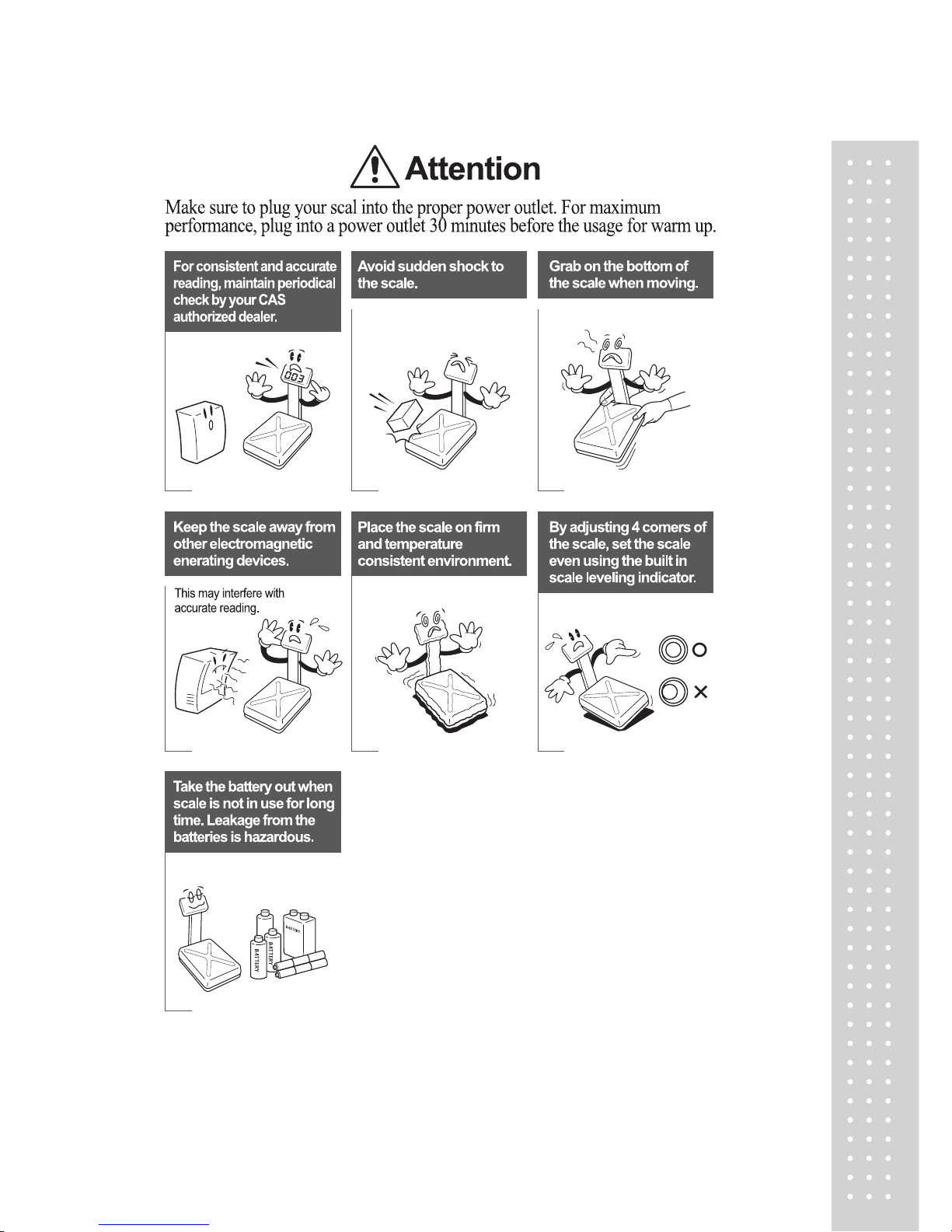
PRECAUTIONS
5
6
PREF ACE
Thank you for purchasing our CAS DB-1/1H series scale.
These series have been designed with CAS reliability, under rigid quality control
and with outstanding performance. Your specialty departments can enjoy these
high quality reliable CAS products.
We believe that your needs will be satisfied and you will have reliability.
This manual will help you with proper operation and are of the DB-1/1H series.
Please keep this handy for future reference.
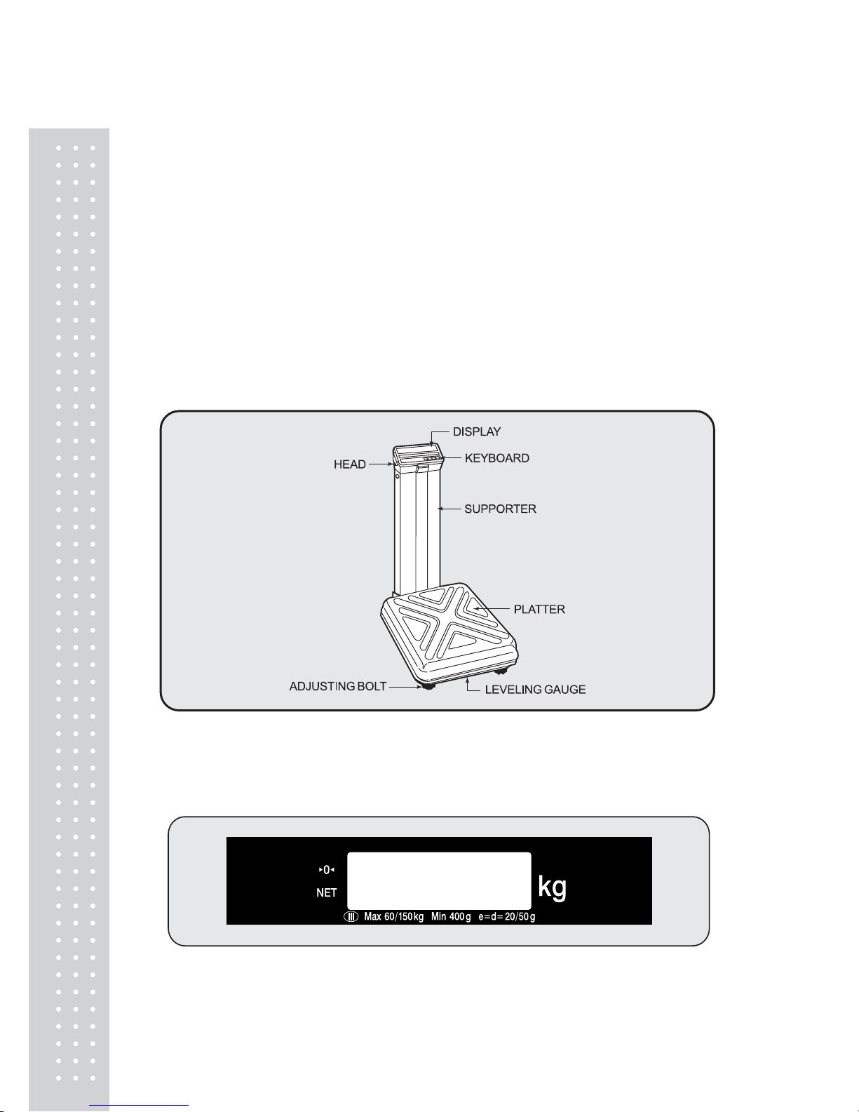
NAMES AND FUNCTIONS
OVERALL VIEW
DISPLA Y
■ DB-1, DB-1H
7
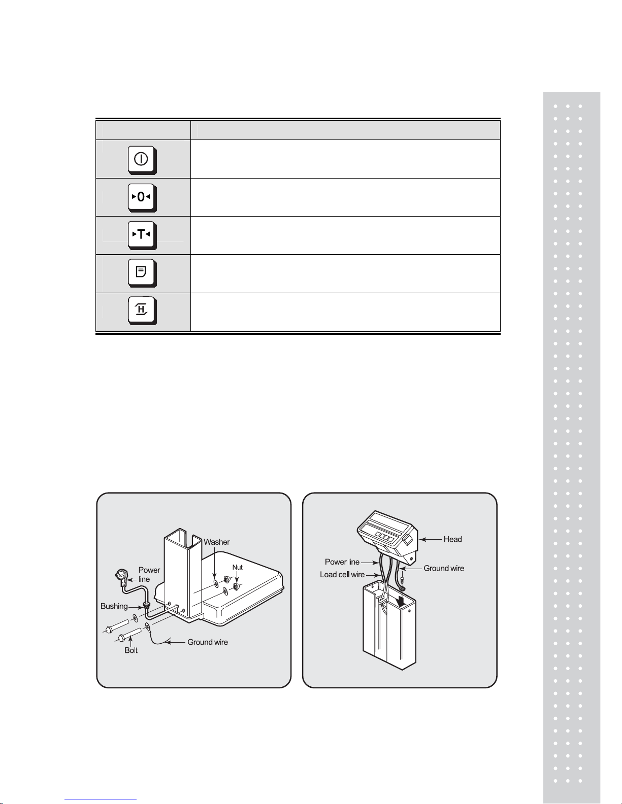
KEYBOARD
KEYS FUNCTIONS
Turn the displays on or off.
Used to correct the zero point.
Used to enter a tare weight.
Used to clear a tare weight.
PRINT FUNCTION (OPTION) – Print version
When the weight is not stable, display will show the average weight
for 4 seconds. – Hold version
※In HOLD Version, printing function could not use and
In Printer version HOLD function is not available.
INSTALLA TIONS
1. Insert the power line into the support.
Fasten with bolts and nuts as fig 1.
2. Fix a ground wire with bolt then
arrange the power line and loadcell
line as fig 2.
fig. 1 fig. 2
 Loading...