

Page 1
CARVIN ENGINEERING DATA XC3000 STEREO 2/3-WAY ELECTRONIC CROSSOVER
OPERATING MANUAL
Stereo 2/3Way Crossover
SUB SONICGAIN
PEAK
LOW LEVEL
LOW LEVEL
MID LEVEL HIGH LEVEL
HIGH LEVEL
LOW / MID
LOW/HIGH
MID / HIGH
40Hz
OFF
3 WAY
2 WAY
x1
x10
CHANNEL ONE
PWR
XC3000
24dB/OCTAVE
CHANNEL TWO
+6
0dB
SUB SONICGAIN
PEAK
LOW LEVEL
LOW LEVEL
MID LEVEL HIGH LEVEL
HIGH LEVEL
LOW / MID
LOW/HIGH
MID / HIGH
40Hz
OFF
3 WAY
2 WAY
x1
x10
kHzHz
50
90
200 450
600
1k
FREQUENCY
FREQUENCY
ON
OFF
+6
0dB
+6
0dB+60dB
300300 3.0
0.6
2.0 5.0
0.8 7.0
10
+6
0dB
kHzHz
50
90
200 450
600
1k
+6
0dB
+6
0dB+60dB
300 3.0
0.6
2.0 5.0
0.8 7.0
10
Congratulations on your purchase of the CARVIN XC3000 Stereo 2 / 3 - way
Electronic Crossover. The XC3000 was designed with the professional in mind.
Your unit has been engineered and assembled in the U.S.A., using only high
quality electronic components and uncompromising workmanship. The XC3000
provides the best available crossover networks consisting of a forth-order statevariable implementation of Linkwitz-Riley crossover alignments. This provides a
24 dB/octave slope while maintaining optimal phase integrity. The XC3000 contains a host of valuable features found in only the best of professional audio
equipment. These include a switchable 40Hz Sub Sonic filter, a 10x frequency
multiplier, switchable Tri-Amp and Bi-Amp modes, balanced input and output
connectors, and phase inversion switches. The XC3000 is designed for maximum signal quality and control, and should give you years of trouble free service.
BI-AMP & TRI-AMP THEORY
Bi-Amplification and Tri-Amplification involve higher protection to
sound systems as well as increased performance. Bi-Amping involves
dividing a full range signals into two distinct low pass and high pass
(low frequency and high frequency) signals and then amplifying these
signals with separate amplifiers for later connection to their proper
woofer and horn speakers.
Tri-Amplification involves the same principle as Bi-Amping except that
separate high-pass, mid band, and low pass signals are fed to (3) separate amplifiers for subsequent connection to woofer, midrange, and
high frequency speakers.
These frequency divisions are done actively with an efficient
24dB/octave roll off prior to the power amplifiers. This allows the amplifiers to power a defined frequency range (low, mid or high) instead of a
full range frequency signal. Due to increased efficiency of the amplifier
(amplifying a distinct frequency range), a cleaner, and more powerful
output is afforded. Bi/Tri-Amplifying is especially useful in selecting any
number of various crossover points and adjusting individual frequency
level gain., thus enabling you to better control the overall response of
your sound system. Bi/Tri-Amplification is useful as a means of offering greater protection, more power with less distortion and better overall control of your sound system.
RECEIVING INSPECTION
INSPECT YOUR XC3000 FOR ANY DAMAGE which may have occurred during shipping. If any damage is found, notify the shipping company and call
CARVIN immediately.
SAVE THE CARTON & ALL PACKING MATERIALS. In the event you have to
reship your mixer, always use the original carton and packing material. This will
provide the best possible protection for your unit during shipment. CARVIN and
the shipping company are not liable for any damage caused by improper packing.
SAVE YOUR INVOICE. It will be required for warranty servicing of your unit.
Always check your invoice against the items you have received.
SHIPMENT SHORTAGE. If you find items missing, it may be that they were
shipped separately. Please allow several days for the rest of your order to
arrive before inquiring. If you determine (after allowing an appropriate amount
of time) you have not received all the items you ordered, please call CARVIN
TROUBEL SHOOTING
SAVE YOUR INVOICE. It will be required for warranty servicing of your unit.
Always check your invoice against the items you have received.
SHIPMENT SHORTAGE. If you find items missing, it may be that they were
shipped separately. Please allow several days for the rest of your order to
arrive before inquiring. If you determine (after allowing an appropriate amount
of time) you have not received all the items you ordered, please call CARVIN
If you determine (after allowing an appropriate amount of time) you have not
received all the items you ordered, please call CARVIN
XC3000 SPECIFICATIONS:
FREQUENCY RESPONSE: 20 Hz to 20k Hz ± 1 dB
THD: Less than .01% 20 to 20k Hz
OUTPUT (BALANCED): +26 dBm
DYNAMIC RANGE: 112 dB
CHANNELS: Two Stereo 2 or 3 Way
INPUT GAIN CONTROL: One per channel
MAX. GAIN ABOVE INPUT SOURCE: 12dB
PEAK LED DETECTOR: Input detection at +16 dBm
SUB SONIC FILTER: 18 dB / Octave -3dB at 40Hz
CROSSOVER FILTER DESIGN.: 24 dB / Octave Linkwitz Riley
LOW / MID CROSSOVER FREQ.: One 50 to 10 Hz sweep per channel
MID / HIGH CROSSOVER FREQ.: One 600 to 10 k Hz sweep per channel
FREQ. MULTIPLIER: One x1 / x10 push button switch per channel
MULTIPLIER RANGE: x1 (95 to 1.6k Hz) and x10 (950 to 16k Hz)
INPUT IMPEDANCE: 22k Ω
INPUT CONNECTORS: Balanced XLR and balanced (stereo)
1 / 4” phone jacks
OUTPUT CONTROL: Three per channel (Low, Mid, HIgh Freq.)
OUTPUT IMPEDANCE: Less than 150 Ω
OUTPUT CONNECTORS: Balanced XLR
PHASE INVERSION: 3 Phase inverting switches per channel
MODE SWITCH: Bi-Amp or Tri-Amp position per channel
POWER REQUIREMENTS: 90 / 250 VAC 50-60 Hz auto switching
FUSE: 3 Amp 250v fast blow
DIMENSIONS: 19”W x 5” D x 1.7”H
SHIPPING WT: 8 lbs
For you records, record the following information.
Serial No._________________ Invoice Date________________
12340 World Trade Drive San Diego, CA 92128
858.487.1600 800. 854.2235
carvin.com
Page 2
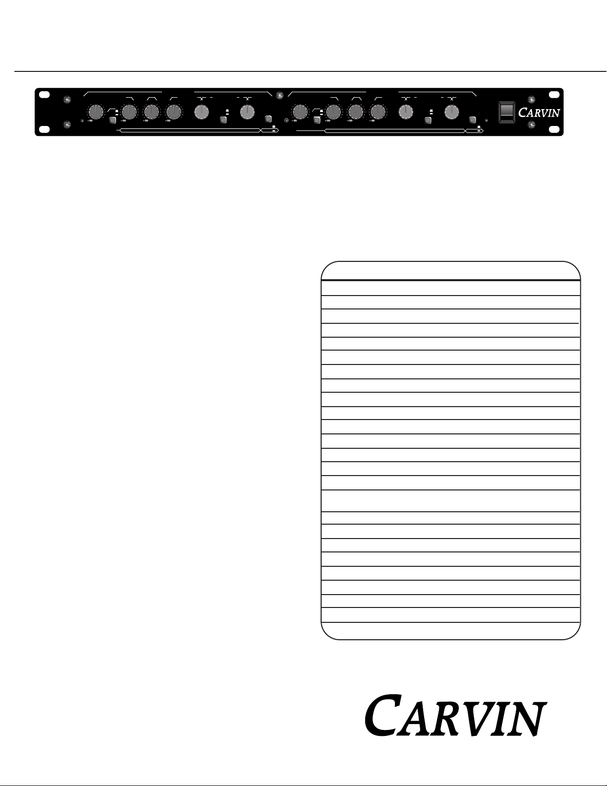
FRONT PANEL FEATURES
Stereo 2/3Way Crossover
SUB SONICGAIN
PEAK
LOW LEVEL
LOW LEVEL
MID LEVEL HIGH LEVEL
HIGH LEVEL
LOW / MID
LOW/HIGH
MID / HIGH
40Hz
OFF
3 WAY
2 WAY
x1
x10
CHANNEL ONE
PWR
XC3000
24dB/OCTAVE
CHANNEL TWO
+6
0dB
SUB SONICGAIN
PEAK
LOW LEVEL
LOW LEVEL
MID LEVEL HIGH LEVEL
HIGH LEVEL
LOW / MID
LOW/HIGH
MID / HIGH
40Hz
OFF
3 WAY
2 WAY
x1
x10
kHzHz
50
90
200 450
600
1k
FREQUENCY
FREQUENCY
ON
OFF
+6
0dB
+6
0dB+60dB
300300 3.0
0.6
2.0 5.0
0.8 7.0
10
+6
0dB
kHzHz
50
90
200 450
600
1k
+6
0dB
+6
0dB+60dB
300 3.0
0.6
2.0 5.0
0.8 7.0
10
1
2
3
4
5
6
7
8
9
10
1. PEAK INDICATOR
The peak indication LED light is used to monitor both input and output distortion. THis indicator will flash whenever any of these
two conditions or a combination of these condition exist. Should the peak indicator ever flash, you can compensate this condition by
adjusting the gain control down (lower) accordingly.
2. GAIN
This control establishes the amount of input gain for the crossover. This control will also affect the output drive of the crossover
thereby adjusting the overall gain of the crossover as well. Note: This control is best used in conjunction with the “peak” level
indicator as a means of monitoring the amount of input gain and output distortion as it relates to any overload conditions.
3. SUB SONIC FILTER
This button provides a third-order high pass filter set at 40Hz. This allows you to reduce sub sonic noise, allowing your power
amps and speakers to operate safely and more efficiently.
4. LOW LEVEL
The LOW LEVEL control sets the output level for the channels LOW OUT jack. Which frequencies will be cut or boosted at this control is dictated by the position of the LOW/MID frequency selector. For example, if the LOW/MID frequency control is set at
300Hz, the frequencies at and below 300Hz will be volumetrically boosted or cut by adjustment of the LOW LEVEL control.
5. MID LEVEL
The MID LEVEL control sets the output level for the channels MID OUT jack. Which frequencies will be cut or boosted at this control is determined by the positions of the LOW/MID and MID/HIGH frequency selectors.
6. HIGH LEVEL
The HIGH LEVEL control sets the output level for the channels HIGH OUT jack. Which frequencies will be cut or boosted at this control is determined by the position of the MID/HIGH frequency selector.
7. LOW / MID FREQUENCY SELECTOR
This control sets the desired upper frequency crossover point for the LOW OUT and lower frequency crossover point for the MID
OUT. The frequency indicated by the knob pointer of this control establishes the LOW/MID crossover point for the channel.
8. 1X / 10X BUTTON
This button multiplies the selected frequency for the LOW / MID crossover network, by 1X or 10X as needed to establish a full
range frequency spectrum from 50Hz to 10kHz. With the 1X button in the “out” position the crossover will sweep from 50Hz to
1kHz. With the 10X button pushed “in” the crossover has a range from 500Hz to 10kHz.
9. MID / HIGH FREQUENCY SELECTOR
This control sets the desired upper frequency crossover point for the MID OUT and lower frequency crossover point for the HIGH
OUT. The frequency indicated by the knob pointer of this control establishes the MID / HIGH crossover point for the channel.
10. 2 WAY / 3 WAY BUTTON
This switch sets the XC3000 into either Bi-Amp or Tri-Amp mode. In the out position the unit is set for Tri-Amp mode. When the
button is depressed the unit will operate in Bi-Amp mode, and the MID LEVEL control and output jack is not used.
11. POWER INDICATOR
This LED illuminates when power is applied to the unit.
12. POWER SWITCH
Push this switch vertically to the “on” position to apply power to the unit. The power indicator LED will light to show that the
XC3000 is on.
CHANNEL TWO
The controls of Channel “TWO” are identical to the controls of Channel “ONE”.
11
12
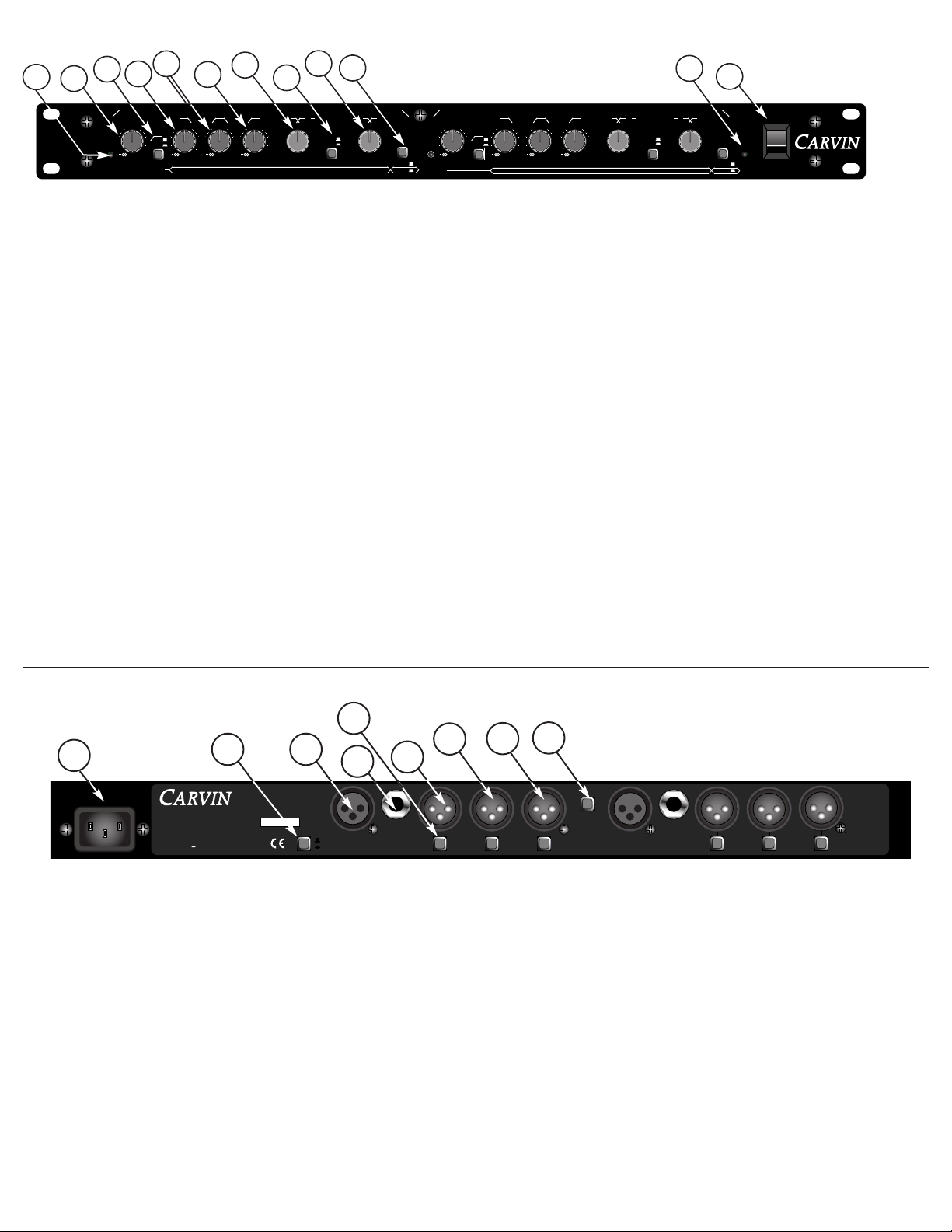
1. LINE CORD
All Carvin equipment is supplied with 3 conductor line cords for maximum safety, greatly reducing the chance of electrical shock.
If the XC3000 unit is to be plugged into a (2) prong outlet, use a quality 3 to 2 prong grounded adapter. Do not defeat the grounding
pin of your AC line cord as this is for your protection.
2. GROUND LIFT SWITCH
Useful in getting rid of ground loop buzzing. This switch lifts the grounds on the nputs and outputs.
3. BALANCED XLR INPUT
Offers the best connection to the XC3000. The XLR connector wiring is as follows: Pin #1 ground, Pin #2 Positive Balance, Pin #3
Negative Balance.
4. BALANCED 1 / 4” PHONE INPUT
The balanced 1 / 4” phone input jack will accept either balanced or non-balanced connections. For best results use balanced (Tip,
Ring, Sleeve) connections to reduce cable hum.
5. PHASE INVERTER SWITCH
The PHASE inverter switch gives you the option of inverting the phase
of each of the main output to correct any phase inversion problem at your speakers or power amps.
6. LOW OUT XLR
The LOW OUT 1 / 4” phone jack provides a balanced output for the low pass filter of the channel. This is where you connect the
power amp that will be driving your bass cabinets.
7. MID OUT XLR
The MID OUT 1 / 4” phone jack provides a balanced output for the band pass filter of the channel. This is where you connect the
power amp that will be driving your mid range cabinets.
8. HIGH OUT XLR
The HIGH OUT 1 / 4” phone jack provides a balanced output for the high pass filter of the channel. This is where you connect the
power amp that will be driving your high frequency horns or tweeters.
9. MONO (LOW 1+2) SWITCH
Combines both signals from each channel’s low pass filters. Either or both LOW outputs may be used. This is where you would
connect a power amp to drive a mono subwoofer sustem.
REAR PANEL FEATURES
1-800-854-2235
www.carvin.com
MADE
AUS
IN THE
XC3000
Electronic Crossover
CHANNEL ONE
SERIAL NUMBER
MONO
[ LOW 1+2 ]
INPUT INPUT
CHANNEL TWO
PHASE
HIGH
PHASE
MID
PHASE
LOW
PHASE
HIGH
PHASE
MID
PHASE
LOW
[ LOW 1+2 ]
TO MONO
SWITCHABLE
90-250 VAC
INTERNAL FUSE
10 VA 50-60Hz
GND
LIFT
1
3
4
5
7
8
6
9
2
Page 3

MONO BI-AMPING
If your system requires only mono bi-amplification, you will utilize only one side of the XC3000 “CHANNEL ONE”.
Simply plug your full range frequency source into the “CHANNEL ONE” 1/4 “ PHONE or XLR input connector at the
rear panel of the XC3000. Then connect the “LOW OUT” and “HIGH OUT” XLR jacks to the input of your power amplifier. Note: If a stereo amplifier is used, you will male your connections to either side “Channel 1” or “Channel 2” of
the amplifier as respectively used in connection to the horns and woofers of your sound system.
Depress the “2 WAY / 3 WAY” selector switch on the front panel of the XC3000 so that the unit will operate in BIAmp mode. Now set the “GAIN” of “CHANNEL ONE” to “0” dB (center of rotation). Set the “LOW LEVEL” and “HIGH
LEVEL” controls to -∞ (off position). Adjust the “LOW / HIGH” frequency selector knob to the approximate desired
crossover point. If the desired crossover frequency is above 1kHz, depress the “x10” multiplier switch.
Now power up your system. Note: your power amplifiers should be the last piece of equipment to turn on, and the
first piece to turn off when applying and removing power from a sound system. Send a typical full range signal into
the XC3000 and slowly bring up the “LOW LEVEL” control until the desired volume level is realized. Then bring up the
“HIGH LEVEL” control until the highs and lows sound well balanced. Now you can fine tune the crossover frequency by
adjusting the “LOW / HIGH” frequency selector knob.
STEREO BI-AMPING
Stereo bi-amplification works in exactly the same manner as in mono bi-amping except that you have two full range
input sources (stereo inputs). Make one connection from the stereo source to one side (CHANNEL ONE) of the XC3000
and connect the other source to (CHANNEL TWO) of the XC3000. The crossover frequency separation will work in
the exact same manner as in mono biamplification, however, “CHANNEL ONE” will bi-amplify one side of your stereo
system. Note: In stereo biamplification you will have to utilize four separate power amplifiers or two stereo amplifiers. This will be required to amplify both low pass (woofer) and high pass (horn) signals to your stereo speaker
array. As a general rule, the high pass amplifiers of your stereo speaker array only have to be 1 / 3 the wattage of
the low pass amplifiers due to the higher efficiency and lower power consumption of the horns. Be sure to adjust the
gain controls and level controls for each channel so that the “PEAK” indicator LED does not flash. Also be careful to
note the position of the (1X / 10X) switch per channel, and the respective frequency crossover point in order not to
deliver harmful low frequencies to the horn arrays.
MONO BI-AMP CONFIGURATION
System Requirements:
A) Mono source (Mixer)
B) One Stereo Power Amp
C) Individual Horn and Woofer Connections
Crossover
Input
LEFT
BASS CABINET
LEFT HORN RIGHT HORN
AUS
8
MONO
BRIDGE
–
+
+
–
INPUTS OUTPUTSACCESSORY GROUP
SPEAKER IMPEDANCE
7
6
5
4
3
2
1
RMS POWERMAX
BALANCED LINE SPEAKER
®
121
2
FUSE
Mixer Output
PHASE
AUS
XC3000
Electronic Crossover
IN
OUT
CHANNEL TWO CHANNEL ONE
LOW OUT MID OUT HIGH OUT LOW OUT MID OUT HIGH OUT LOW OUT
SUM
S/N REMOVED
INPUT
IN
OUTINOUT
IN
OUTINOUTINOUT
PHASE PHASE PHASE PHASE PHASE
CH 1/2
50-60Hz 20VA
120V 240V
MON 1 EFF 1 EFF 2
BAL SENDS
LEFT/3 RIGHT/4 MAIN
R
POWER
L
SENDS
C
CNTRL
STEREO RETURNS
TAPE SEND
LR
B
A
MON 2
RM
LAMP
12V
SUB 1 PHONESSUB 2
USE HIGH CURRENT SPEAKER CABLE
FOR ALL SPEAKER CONNECTIONS
CARVIN PART # XP-50
2 COND (TIP/RING) OR
3 COND (TIP/RING/SLEEVE)
SHIELDED CABLE
SUB SONICGAIN
PEAK
LOW LEVEL
LOW LEVEL
MID LEVEL
HIGH LEVEL
HIGH LEVEL
LOW / MID
LOW/HIGH
MID / HIGH
40Hz
OFF
3 WAY
2 WAY
x1
x10
Stereo 2/3Way Crossover
dB+6
CHANNEL ONE
PWR
XC3000
24dB/OCTAVE
CHANNEL TWO
0
dB+6
0
dB+60dB+6
0
SUB SONICGAIN
PEAK
LOW LEVEL
LOW LEVEL
MID LEVEL
HIGH LEVEL
HIGH LEVEL
LOW / MID
LOW/HIGH
MID / HIGH
40Hz
OFF
3 WAY
2 WAY
x1
x10
dB+6
0
dB+6
0
dB+60dB+6
0
kHzHz50
90
200 450
6001k0.8
2.0 5.0
7.0
100.6
FREQUENCY
300 3.0
kHzHz50
90
200 450
6001k0.8
2.0 5.0
7.0
100.6
FREQUENCY
300 3.0
ON
OFF
Set the intput "GAIN" so that the
"PEAK" LED does not illuminate.
Adjust your output level controls
for the desired balance.
Set for Bi-Amp mode.
Set your input "GAIN" so that you
run your signal source (mixer) at its
nominal volume setting.
Adjust these controls to set your
crossover frequency point.
RIGHT
BASS CABINET
MONO MAIN (BAL or NON-BAL)
LOW OUT
HIGH OUT
SPEAKERS DAISY CHAINED
THROUGH JACK PLATE
INPUT
STEREO BI-AMP CONFIGURATION
System Requirements:
A) Stereo source (Mixer)
B) Two Stereo Power Amps
C) Individual Horn and Woofer Connections
Low Amplifier
Crossover
Input
High Amplifier
LEFT
BASS CABINET
LEFT HORN RIGHT HORN
RIGHT
BASS CABINET
AUS
8
MONO
BRIDGE
–
+
+
–
INPUTS OUTPUTSACCESSORY GROUP
SPEAKER IMPEDANCE
7
6
5
4
3
2
1
RMS POWERMAX
BALANCED LINE SPEAKER
®
121
2
FUSE
AUS
8
MONO
BRIDGE
–
+
+
–
INPUTS OUTPUTSACCESSORY GROUP
SPEAKER IMPEDANCE
7
6
5
4
3
2
1
RMS POWERMAX
BALANCED LINE SPEAKER
®
121
2
FUSE
Mixer Output
PHASE
AUS
XC3000
Electronic Crossover
IN
OUT
CHANNEL TWO CHANNEL ONE
LOW OUT MID OUT HIGH OUT LOW OUT MID OUT HIGH OUT LOW OUT
SUM
S/N REMOVED
INPUT
IN
OUTINOUT
IN
OUTINOUTINOUT
PHASE PHASE PHASE PHASE PHASE
CH 1/2
50-60Hz 20VA
120V 240V
MON 1 EFF 1 EFF 2
BAL SENDS
LEFT/3 RIG HT/4 MAIN
R
POWER
L
SENDS
C
CNTRL
STEREO RETURNS
TAPE SEND
LR
B
A
MON 2
RM
LAMP
12V
SUB 1 PHONESSUB 2
RIGHT (BAL or NON-BAL)
LEFT (BAL or NON-BAL)
USE HIGH CURRENT SPEAKER CABLE
FOR ALL SPEAKER CONNECTIONS
CARVIN PART # XP-50
2 COND (TIP/RING) OR
3 COND (TIP/RING/SLEEVE)
SHIELDED CABLE
SUB SONICGAIN
PEAK
LOW LEVEL
LOW LEVEL
MID LEVEL
HIGH LEVEL
HIGH LEVEL
LOW / MID
LOW/HIGH
MID / HIGH
40Hz
OFF
3 WAY
2 WAY
x1
x10
Stereo 2/3Way Crossover
dB+6
CHANNEL ONE
PWR
XC3000
24dB/OCTAVE
CHANNEL TWO
0
dB+6
0
dB+60dB+6
0
SUB SONICGAIN
PEAK
LOW LEVEL
LOW LEVEL
MID LEVEL
HIGH LEVEL
HIGH LEVEL
LOW / MID
LOW/HIGH
MID / HIGH
40Hz
OFF
3 WAY
2 WAY
x1
x10
dB+6
0
dB+6
0
dB+60dB+6
0
kHzHz50
90
200 450
6001k0.8
2.0 5.0
7.0
100.6
FREQUENCY
300 3.0
kHzHz50
90
200 450
6001k0.8
2.0 5.0
7.0
100.6
FREQUENCY
300 3.0
ON
OFF
Set the intput "GAIN" so that the
"PEAK" LED does not illuminate.
Adjust your output level controls
for the desired balance.
Set for Bi-Amp mode.
Set your input "GAIN" so that you
run your signal source (mixer) at its
nominal volume setting.
Adjust these controls to set your
crossover frequency point.
INPUT
L
LR
R
BI-AMPLIFYING WITH THE XC3000
Page 4

STEREO TRI-AMP CONFIGURATION
System Requirements:
A) Stereo source (Mixer)
B) Three Stereo Power Amps
C) Individual Horn, Mid, and Woofer Connections
Low Amplifier
Crossover
Input
Mid Amplifier
AUS
8
MONO
BRIDGE
–
+
+
–
INPUTS OUTPUTSACCESSORY GROUP
SPEAKER IMPEDANCE
7
6
5
4
3
2
1
RMS POWERMAX
BALANCED LINE
SPEAKER
®
121
2
FUSE
AUS
8
MONO
BRIDGE
–
+
+
–
INPUTS OUTPUTSACCESSORY GROUP
SPEAKER IMPEDANCE
7
6
5
4
3
2
1
RMS POWERMAX
BALANCED LINE
SPEAKER
®
121
2
FUSE
Mixer Output
PHASE
AUS
XC3000
Electronic Crossover
IN
OUT
CHANNEL TWO CHANNEL ONE
LOW OUT MID OUT HIGH OUT LOW OUT MID OUT HIGH OUT LOW OUT
SUM
S/N REMOVED
INPUT
IN
OUTINOUT
IN
OUTINOUTINOUT
PHASE PHASE PHASE PHASE PHASE
CH 1/2
50-60Hz 20VA
120V 240V
MON 1 EFF 1 EFF 2
BAL SENDS
LEFT/3 RIGHT/4 MAIN
R
POWER
L
SENDS
C
CNTRL
STEREO RETURNS
TAPE SEND
LR
B
A
MON 2
RM
LAMP
12V
SUB 1 PHONESSUB 2
USE HIGH CURRENT SPEAKER CABLE
FOR ALL SPEAKER CONNECTIONS
CARVIN PART # XP-50
2 COND (TIP/RING) OR
3 COND (TIP/RING/SLEEVE)
SHIELDED CABLE
INPUT
RIGHT
BASS CABINET
RIGHT HORN
RIGHT
MID CABINET
LEFT
BASS CABINET
LEFT HORN
LEFT
MID CABINET
AUS
8
MONO
BRIDGE
–
+
+
–
INPUTS OUTPUTSACCESSORY GROUP
SPEAKER IMPEDANCE
7
6
5
4
3
2
1
RMS POWERMAX
BALANCED LINE SPEAKER
®
121
2
FUSE
High Amplifier
LEFT (BAL or NON-BAL)
RIGHT (BAL or NON-BAL)
SUB SONICGAIN
PEAK
LOW LEVEL
LOW LEVEL
MID LEVEL
HIGH LEVEL
HIGH LEVEL
LOW / MID
LOW/HIGH
MID / HIGH
40Hz
OFF
3 WAY
2 WAY
x1
x10
Stereo 2/3Way Crossover
dB+6
CHANNEL ONE
PWR
XC3000
24dB/OCTAVE
CHANNEL TWO
0
dB+6
0
dB+6
0
dB
+6
0
SUB SONICGAIN
PEAK
LOW LEVEL
LOW LEVEL
MID LEVEL
HIGH LEVEL
HIGH LEVEL
LOW / MID
LOW/HIGH
MID / HIGH
40Hz
OFF
3 WAY
2 WAY
x1
x10
dB+6
0
dB+6
0
dB+6
0
dB
+6
0
kHzHz50
90
200 450
6001k0.8
2.0 5.0
7.0
100.6
FREQUENCY
300 3.0
kHzHz50
90
200 450
6001k0.8
2.0 5.0
7.0
100.6
FREQUENCY
300 3.0
ON
OFF
Set the intput "GAIN" so that the
"PEAK" LED does not illuminate.
Adjust your output level controls
for the desired balance.
Set forTri-Amp mode.
Set your input "GAIN" so that you
run your signal source (mixer) at its
nominal volume setting.
Adjust these controls to set your
crossover frequency point.
L
R
L
L
R
R
MONO TRI-AMP CONFIGURATION
System Requirements:
A) Mono source (Mixer)
B) One Stereo Power Amp & One Mono Power Amp
C) Individual Horn, Mid, and Woofer Connections
Low Amplifier
Crossover
Input
Mid Amplifier
AUS
8
MONO
BRIDGE
–
+
+
–
INPUTS OUTPUTSACCESSORY GROUP
SPEAKER IMPEDANCE
7
6
5
4
3
2
1
RMS POWERMAX
BALANCED LINE SPEAKER
®
121
2
FUSE
AUS
8
MONO
BRIDGE
–
+
+
–
INPUTS OUTPUTSACCESSORY GROUP
SPEAKER IMPEDANCE
7
6
5
4
3
2
1
RMS POWERMAX
BALANCED LINE SPEAKER
®
121
2
FUSE
Mixer Output
PHASE
AUS
XC3000
Electronic Crossover
IN
OUT
CHANNEL TWO CHANNEL ONE
LOW OUT MID OUT HIGH OUT LOW OUT MID OUT HIGH OUT LOW OUT
SUM
S/N REMOVED
INPUT
IN
OUTINOUT
IN
OUTINOUTINOUT
PHASE PHASE PHASE PHASE PHASE
CH 1/2
50-60Hz 20VA
120V 240V
MON 1 EFF 1 EFF 2
BAL SENDS
LEFT/3 RIGHT/4 MAIN
R
POWER
L
SENDS
C
CNTRL
STEREO RETURNS
TAPE SEND
LR
B
A
MON 2
RM
LAMP
12V
SUB 1 PHONESSUB 2
USE HIGH CURRENT SPEAKER CABLE
FOR ALL SPEAKER CONNECTIONS
CARVIN PART # XP-50
2 COND (TIP/RING) OR
3 COND (TIP/RING/SLEEVE)
SHIELDED CABLE
MONO MAIN (BAL or NON-BAL)
INPUT
RIGHT
BASS CABINET
RIGHT HORN
RIGHT
MID CABINET
SPEAKERS DAISY CHAINED
THROUGH JACK PLATE
SET "PARALLEL INPUTS" SWITCHES
TO RIGHT-MOST POSITION
LEFT
BASS CABINET
LEFT HORN
LEFT
MID CABINET
SUB SONICGAIN
PEAK
LOW LEVEL
LOW LEVEL
MID LEVEL
HIGH LEVEL
HIGH LEVEL
LOW / MID
LOW/HIGH
MID / HIGH
40Hz
OFF
3 WAY
2 WAY
x1
x10
Stereo 2/3Way Crossover
dB+6
CHANNEL ONE
PWR
XC3000
24dB/OCTAVE
CHANNEL TWO
0
dB+6
0
dB+6
0
dB
+6
0
SUB SONICGAIN
PEAK
LOW LEVEL
LOW LEVEL
MID LEVEL
HIGH LEVEL
HIGH LEVEL
LOW / MID
LOW/HIGH
MID / HIGH
40Hz
OFF
3 WAY
2 WAY
x1
x10
dB+6
0
dB+6
0
dB+6
0
dB
+6
0
kHzHz50
90
200 450
6001k0.8
2.0 5.0
7.0
100.6
FREQUENCY
300 3.0
kHzHz50
90
200 450
6001k0.8
2.0 5.0
7.0
100.6
FREQUENCY
300 3.0
ON
OFF
Set the intput "GAIN" so that the
"PEAK" LED does not illuminate.
Adjust your output level controls
for the desired balance.
Set forTri-Amp mode.
Set your input "GAIN" so that you
run your signal source (mixer) at its
nominal volume setting.
Adjust these controls to set your
crossover frequency point.
MONO TRI-AMPING
To use the XC3000 in a Tri-Amped sound system, connect your full range frequency sources into the “CHANNEL
ONE” 1 / 4” PHONE or XLR input connectors at the rear panel of the XC3000. Then connect the “CHANNEL ONE”
“LOW OUT”, “MID OUT”, and “HIGH OUT” phone XLR jacks to the inputs of your power amplifiers. Note: this will
require three separate amplifier channels. If you will be using two stereo power amps connect the mids and highs
to channels one and two of one amp. Operate the second power amp in bridged mode and make the connections for
the lows.
Set the “2 WAY / 3 WAY” selector switch on the front panel of the XC3000 so that the unit will operate in Tri-Amp
mode. Now set the “GAIN” control of “CHANNEL ONE” to “0” dB (center of rotation). Set the “LOW LEVEL” , “MID
LEVEL”, and “HIGH LEVEL” controls to -∞ (off position). Adjust the “LOW / MID” and “MID / HIGH” frequency selector knobs to the approximate desired crossover points.
Power up your system and send signal through your XC3000. Slowly bring up the “LOW LEVEL” control until the
desired volume level is realized. Next bring up the “MID LEVEL” and “HIGH LEVEL” controls until the lows, mids, and
highs sound well balanced. Now you can fine tune the crossover frequencies by adjusting the “LOW / MID” and “MID
/ HIGH” frequency selector knobs.
STEREO TRI-AMPING
Stereo tri-amplification of the XC3000 works in exactly the same manner as in mono tri-amping except that you utilize
both channels, and power two sets of speaker cabinets.
TRI-AMPLIFYING WITH THE XC3000
Page 5

MONO QUAD AMP CONFIGURATION
SSyysstteemm RReeqquuiirreemmeennttss::
A) Stereo Source (Mixer)
B) Four Stereo Power Amps
C) Individual Horn, MID, and Sub Woofer Connections
Sub/Low Amplifier
Crossover
Input
AUS
8
MONO
BRIDGE
–
+
+
–
INPUTS OUTPUTSACCESSORY GROUP
SPEAKER IMPEDANCE
7
6
5
4
3
2
1
RMS POWERMAX
BALANCED LINE SPEAKER
®
121
2
FUSE
Mixer Output
PHASE
AUS
XC3000
Electronic Crossover
IN
OUT
CHANNEL TWO CHANNEL ONE
LOW OUT MID OUT HIGH OUT LOW OUT MID OUT HIGH OUT LOW OUT
SUM
S/N REMOVED
INPUT
IN
OUTINOUT
IN
OUTINOUTINOUT
PHASE PHASE PHASE PHASE PHASE
CH 1/2
50-60Hz 20VA
120V 240V
MON 1
EFF 1 EFF 2
BAL SENDS
LEFT/3 RIGHT/4 MAIN
R
POWER
L
SENDS
C
CNTRL
STEREO RETURNS
TAPE SEND
LR
B
A
MON 2
RM
LAMP
12V
SUB 1 PHONESSUB 2
USE HIGH CURRENT SPEAKER CABLE
FOR ALL SPEAKER CONNECTIONS
CARVIN PART # XP-50
2 COND (TIP/RING) OR
3 COND (TIP/RING/SLEEVE)
SHIELDED CABLE
INPUT
RIGHT
BASS CABINET
RIGHT HORN
LEFT
BASS CABINET
LEFT HORN
AUS
8
MONO
BRIDGE
–
+
+
–
INPUTS OUTPUTSACCESSORY GROUP
SPEAKER IMPEDANCE
7
6
5
4
3
2
1
RMS POWERMAX
BALANCED LINE SPEAKER
®
121
2
FUSE
Mid/High Amplifier
LEFT
MID CABINET
RIGHT
MID CABINET
LEFT
SUB CABINET
RIGHT
SUB CABINET
SPEAKERS DAISY CHAINED
THROUGH JACK PLATE
PATCH (BAL or NON-BAL)
MONO MAIN (BAL or NON-BAL)
SUB OUT LOW OUT MID OUT HIGH OUT
SUB SONICGAIN
PEAK
LOW LEVEL
LOW LEVEL
MID LEVEL
HIGH LEVEL
HIGH LEVEL
LOW / MID
LOW/HIGH
MID / HIGH
40Hz
OFF
3 WAY
2 WAY
x1
x10
Stereo 2/3Way Crossover
dB+6
CHANNEL ONE
PWR
XC3000
24dB/OCTAVE
CHANNEL TWO
0
dB+6
0
dB+6
0
dB
+6
0
SUB SONICGAIN
PEAK
LOW LEVEL
LOW LEVEL
MID LEVEL
HIGH LEVEL
HIGH LEVEL
LOW / MID
LOW/HIGH
MID / HIGH
40Hz
OFF
3 WAY
2 WAY
x1
x10
dB+6
0
dB+6
0
dB+6
0
dB
+6
0
kHzHz50
90
200 450
6001k0.8
2.0 5.0
7.0
100.6
FREQUENCY
300 3.0
kHzHz50
90
200 450
6001k0.8
2.0 5.0
7.0
100.6
FREQUENCY
300 3.0
ON
OFF
Set the intput "GAIN" so that the
"PEAK" LED does not illuminate.
Adjust your output level controls
for the desired balance.
Set forTri-Amp mode.
Set your input "GAIN" so that you
run your signal source (mixer) at its
nominal volume setting.
Adjust these controls to set your
crossover frequency point.
BI-AMP W/ SUB CONFIGURATION
SSyysstteemm RReeqquuiirreemmeennttss::
A) Stereo Source (Mixer)
B) Three Stereo Power Amps
C) Individual Horn, MID, and Sub Woofer Connections
Low Amplifier
Crossover
Input
AUS
8
–
+
+
–
INPUTS OUTPUTSACCESSORY GROUP
SPEAKER IMPEDANCE
7
6
5
4
3
2
1
RMS POWERMAX
BALANCED LINE SPEAKER
®
121
2
FUSE
AUS
8
MONO
BRIDGE
–
+
+
–
INPUTS OUTPUTS
ACCESSORY GROUP
SPEAKER IMPEDANCE
7
6
5
4
3
2
1
RMS POWERMAX
BALANCED LINE SPEAKER
®
121
2
FUSE
Mixer Output
PHASE
AUS
XC3000
Electronic Crossover
IN
OUT
CHANNEL TWO CHANNEL ONE
LOW OUT MID OUT HIGH OUT LOW OUT MID OUT HIGH OUT LOW OUT
SUM
S/N REMOVED
INPUT
IN
OUTINOUT
IN
OUTINOUTINOUT
PHASE PHASE PHASE PHASE PHASE
CH 1/2
50-60Hz 20VA
120V 240V
MON 1 EFF 1 EFF 2
BAL SENDS
LEFT/3 RIGHT/4 MAIN
R
POWER
L
SENDS
C
CNTRL
STEREO RETURNS
TAPE SEND
LR
B
A
MON 2
RM
LAMP
12V
SUB 1 PHONESSUB 2
USE HIGH CURRENT SPEAKER CABLE
FOR ALL SPEAKER CONNECTIONS
CARVIN PART # XP-50
2 COND (TIP/RING) OR
3
COND (TIP/RING/SLEEVE)
SHIELDED CABLE
INPUT
RIGHT
BASS CABINET
RIGHT HORN
LEFT
BASS CABINET
LEFT HORN
AUS
8
MONO
BRIDGE
–
+
+
–
INPUTS OUTPUTS
ACCESSORY GROUP
SPEAKER IMPEDANCE
7
6
5
4
3
2
1
RMS POWERMAX
BALANCED LINE SPEAKER
®
121
2
FUSE
High Amplifier
LEFT (BAL or NON-BAL)
RIGHT (BAL or NON-BAL)
SUB SONICGAIN
PEAK
LOW LEVEL
LOW LEVEL
MID LEVEL
HIGH LEVEL
HIGH LEVEL
LOW / MID
LOW/HIGH
MID / HIGH
40Hz
OFF
3 WAY
2 WAY
x1
x10
Stereo 2/3Way Crossover
dB+6
CHANNEL ONE
PWR
XC3000
24dB/OCTAVE
CHANNEL TWO
0
dB+6
0
dB+6
0
dB
+6
0
SUB SONICGAIN
PEAK
LOW LEVEL
LOW LEVEL
MID LEVEL
HIGH LEVEL
HIGH LEVEL
LOW / MID
LOW/HIGH
MID / HIGH
40Hz
OFF
3 WAY
2 WAY
x1
x10
dB+6
0
dB+6
0
dB+6
0
dB
+6
0
kHzHz50
90
200 450
6001k0.8
2.0 5.0
7.0
100.6
FREQUENCY
300 3.0
kHzHz50
90
200 450
6001k0.8
2.0 5.0
7.0
100.6
FREQUENCY
300 3.0
ON
OFF
Set the intput "GAIN" so that the
"PEAK" LED does not illuminate.
Adjust your output level controls
for the desired balance.
Set forTri-Amp mode.
Set your input "GAIN" so that you
run your signal source (mixer) at its
nominal volume setting.
Adjust these controls to set your
crossover frequency point.
MONO
BRIDGE
SUB WOOFER
Sub Amplifier
AMP IN BRIDGED MODE
R
LRL
MONO SUB-WOOFER
The mono low (1+2) switch on the rear panel can be used when hooking up a single sub-woofer to your system and
get a summed response of both channels. When using this output set the “CHANNEL ONE” and “CHANNEL TWO” “LOW
LEVEL” controls to the same position.
MONO QUAD-AMPING
The XC3000 can be used in four way sound systems. To do this you need to patch the “LOW OUT” XLR phone jack of
“CHANNEL ONE” into the input jack of “CHANNEL TWO”. Now the “CHANNEL TWO” “LOW OUT” and “MID OUT”
jacks will be used to send signal to your sub woofer and bass power amps, and the “CHANNEL ONE” “MID OUT” and
“HIGH OUT” jacks will feed your mids and highs power amps.
1
6
4
2
3
5
9
7
12
10
8
11
13
RREEFF DDEESSCCRRIIPPTTIIOONN PPAARRTT ## QQ
1 XC3000 Chassis 10-30004 1
2 XC3000 Master PCB 80-30000 1
3 Primary Fuse 70-21005 1
4 AC Connector 21-30900 1
5 Torroid 15-00733 1
6 Pan Head Chassis Screw 06-10020 4
7 Knob 07-12028 12
8 Pot 71-14010 8
9 Pot 4x 71-12450 4
10 Pan Head Sheet Metal Screw 06-10050 1
11 XC3000 Front Panel 10-30001 1
12 Switch Cap 07-31160 6
13 Power Switch 25-62116 1
BI AMP W/SUB & MONO QUAD CONFIGURATIONS
XC3000 PARTS LIST
Page 6

RREEFF DDEESSCCRRIIPPTTIIOONN PPAARRTT ## QQttyy
A1 5532, Low Noise Op Amp 60-55320 1
A2 4558, Low Noise Op Amp 60-45580 1
A3 4558, Low Noise Op Amp 60-45580 1
A4 4558, Low Noise Op Amp 60-45580 1
A5 4558, Low Noise Op Amp 60-45580 1
A6 4558, Low Noise Op Amp 60-45580 1
A7 4558, Low Noise Op Amp 60-45580 1
A8 4558, Low Noise Op Amp 60-45580 1
A9 5532, Low Noise Op Amp 60-55320 1
A10 4558, Low Noise Op Amp 60-45580 1
A11 4558, Low Noise Op Amp 60-45580 1
A12 4558, Low Noise Op Amp 60-45580 1
A13 4558, Low Noise Op Amp 60-45580 1
A14 4558, Low Noise Op Amp 60-45580 1
A15 4558, Low Noise Op Amp 60-45580 1
A16 4558, Low Noise Op Amp 60-45580 1
A17 4558, Low Noise Op Amp 60-45580 1
A18 4558, Low Noise Op Amp 60-45580 1
A19 4558, Low Noise Op Amp 60-45580 1
A20 4558, Low Noise Op Amp 60-45580 1
C1 Capacitor, Electrolytic, 10µF 47-10051 1
C2 Capacitor, Electrolytic, 10µF 47-10051 1
C3 Capacitor, Ceramic, 27pF 45-27052 1
C4 Capacitor, Ceramic, 27pF 45-27052 1
C5 Capacitor, Electrolytic, 10µF 47-10051 1
C6 Capacitor, Ceramic, 27pF 45-27052 1
C7 Capacitor, Poly, 0.22µF 46-22412 1
C8 Capacitor, Poly, 0.22µF 46-22412 1
C9 Capacitor, Poly, 0.22µF 46-22412 1
C10 Capacitor, Electrolytic, 10µF 47-10051 1
C11 Capacitor, Electrolytic, 10µF 47-10051 1
C12 Capacitor, Ceramic, 27pF 45-27052 1
C13 Capacitor, Poly, 0.0047µF 46-47212 1
C14 Capacitor, Poly, 0.047µF 46-47312 1
C15 Capacitor, Poly, 0.0047µF 46-47212 1
C16 Capacitor, Poly, 0.047µF 46-47312 1
C17 Capacitor, Poly, 0.0047µF 46-47212 1
C18 Capacitor, Poly, 0.047µF 46-47312 1
C19 Capacitor, Poly, 0.0047µF 46-47212 1
C20 Capacitor, Poly, 0.047µF 46-47312 1
C21 Capacitor, Poly, 0.0047µF 46-47212 1
C22 Capacitor, Poly, 0.0047µF 46-47212 1
C23 Capacitor, Poly, 0.0047µF 46-47212 1
C24 Capacitor, Poly, 0.0047µF 46-47212 1
C25 Capacitor, Poly, 0.0047µF 46-47212 1
C26 Capacitor, Electrolytic, 10µF 47-10051 1
C27 Capacitor, Electrolytic, 10µF 47-10051 1
C28 Capacitor, Electrolytic, 10µF 47-10051 1
C29 Capacitor, Ceramic, 27pF 45-27052 1
C30 Capacitor, Electrolytic, 10µF 47-10051 1
C31 Capacitor, Ceramic, 27pF 45-27052 1
C32 Capacitor, Electrolytic, 10µF 47-10051 1
C33 Capacitor, Ceramic, 27pF 45-27052 1
C34 Capacitor, Ceramic, 27pF 45-27052 1
C35 Capacitor, Ceramic, 27pF 45-27052 1
C51 Capacitor, Electrolytic, 10µF 47-10051 1
C52 Capacitor, Electrolytic, 10µF 47-10051 1
C53 Capacitor, Ceramic, 27pF 45-27052 1
C54 Capacitor, Ceramic, 27pF 45-27052 1
C55 Capacitor, Electrolytic, 10µF 47-10051 1
C56 Capacitor, Ceramic, 27pF 45-27052 1
C57 Capacitor, Poly, 0.22µF 46-22412 1
C58 Capacitor, Poly, 0.22µF 46-22412 1
C59 Capacitor, Poly, 0.22µF 46-22412 1
C60 Capacitor, Electrolytic, 10µF 47-10051 1
C61 Capacitor, Electrolytic, 10µF 47-10051 1
C62 Capacitor, Ceramic, 27pF 45-27052 1
C63 Capacitor, Poly, 0.0047µF 46-47212 1
C64 Capacitor, Poly, 0.047µF 46-47312 1
C65 Capacitor, Poly, 0.0047µF 46-47212 1
C66 Capacitor, Poly, 0.047µF 46-47312 1
C67 Capacitor, Poly, 0.0047µF 46-47212 1
C68 Capacitor, Poly, 0.047µF 46-47312 1
C69 Capacitor, Poly, 0.0047µF 46-47212 1
C70 Capacitor, Poly, 0.047µF 46-47312 1
C71 Capacitor, Ceramic, 27pF 45-27052 1
C72 Capacitor, Poly, 0.0047µF 46-47212 1
C73 Capacitor, Poly, 0.0047µF 46-47212 1
C74 Capacitor, Poly, 0.0047µF 46-47212 1
C75 Capacitor, Poly, 0.0047µF 46-47212 1
C76 Capacitor, Electrolytic, 10µF 47-10051 1
C77 Capacitor, Electrolytic, 10µF 47-10051 1
C78 Capacitor, Electrolytic, 10µF 47-10051 1
C79 Capacitor, Ceramic, 27pF 45-27052 1
C80 Capacitor, Electrolytic, 10µF 47-10051 1
C81 Capacitor, Ceramic, 27pF 45-27052 1
C82 Capacitor, Electrolytic, 10µF 47-10051 1
C83 Capacitor, Ceramic, 27pF 45-27052 1
C101 Capacitor, Electrolytic, 2200µF 47-22225 1
C102 Capacitor, Electrolytic, 2200µF 47-22225 1
C103 Capacitor, Electrolytic, 10µF 47-10051 1
C104 Capacitor, Electrolytic, 10µF 47-10051 1
D1 Diode, 1N4003 61-40030 1
D2 LED, Small Red 60-75320 1
D51 Diode, 1N4003 61-40030 1
D52 LED, Small Red 60-75320 1
D101 Diode, 1N4003 61-40030 1
D102 Diode, 1N4003 61-40030 1
D103 Diode, 1N4003 61-40030 1
D104 Diode, 1N4003 61-40030 1
F1 Clips Fuse Holder 23-03529 2
J1 JACK, .250” 21-01806 1
J2 JACK XLR 21-00300 1
J3 JACK, .250” 21-01806 1
J4 JACK, .250” 21-01806 1
J5 JACK, .250” 21-01806 1
J6 JACK, .250” 21-01806 1
J7 JACK, .250” 21-01806 1
J8 JACK XLR 21-00300 1
J9 JACK, .250” 21-01806 1
J10 JACK, .250” 21-01806 1
J11 JACK, .250” 21-01806 1
P1 POT 16 15F B50KCC 71-14010 1
P2 POT 16 15F 15C50KX4 71-12450 1
P3 POT 16 15F 15C50KX4 71-12450 1
P4 POT 16 15F B50KCC 71-14010 1
P5 POT 16 15F B50KCC 71-14010 1
P6 POT 16 15F B50KCC 71-14010 1
P7 POT 16 15F B50KCC 71-14010 1
P8 POT 16 15F 15C50KX4 71-12450 1
P9 POT 16 15F 15C50KX4 71-12450 1
P10 POT 16 15F B50KCC 71-14010 1
P11 POT 16 15F B50KCC 71-14010 1
P12 POT 16 15F B50KCC 71-14010 1
Q1 Transistor, #2N3391A NPN 60-33910 1
Q51 Transistor, #2N3391A NPN 60-33910 1
P9 POT 16 15F 15C50KX4 71-12450 1
P10 POT 16 15F B50KCC 71-14010 1
P11 POT 16 15F B50KCC 71-14010 1
P12 POT 16 15F B50KCC 71-14010 1
Q1 Transistor, #2N3391A NPN 60-33910 1
Q51 Transistor, #2N3391A NPN 60-33910 1
R1 Resistor, 22K, 1/4W 50-22045 1
R2 Resistor, 22K, 1/4W 50-22045 1
R3 Resistor, 22K, 1/4W 50-22045 1
R4 Resistor, 22K, 1/4W 50-22045 1
R5 Resistor, 12K, 1/4W 50-12045 1
R6 Resistor, 13K, 1/4W 50-13045 1
R7 Resistor, 5.6K, 1/4W 50-56035 1
R8 Resistor, 91K, 1/4W 50-91045 1
R9 Resistor, 100K, 1/4W 50-10055 1
R10 Resistor, 82K, 1/4W 50-82045 1
R11 Resistor, 47K, 1/4W 50-47045 1
R12 Resistor, 47K, 1/4W 50-47045 1
R13 Resistor, 3.3K, 1/4W 50-33035 1
R14 Resistor, 18K, 1/4W 50-18045 1
R15 Resistor, 3.3K, 1/4W 50-33035 1
R16 Resistor, 13K, 1/4W 50-13045 1
R17 Resistor, 3.3K, 1/4W 50-33035 1
R18 Resistor, 18K, 1/4W 50-18045 1
R19 Resistor, 3.3K, 1/4W 50-33035 1
R20 Resistor, 47K, 1/4W 50-47045 1
R21 Resistor, 82K, 1/4W 50-82045 1
R22 Resistor, 47K, 1/4W 50-47045 1
R23 Resistor, 47K, 1/4W 50-47045 1
R24 Resistor, 3.3K, 1/4W 50-33035 1
R25 Resistor, 18K, 1/4W 50-18045 1
R26 Resistor, 3.3K, 1/4W 50-33035 1
R27 Resistor, 13K, 1/4W 50-13045 1
R28 Resistor, 3.3K, 1/4W 50-33035 1
R29 Resistor, 18K, 1/4W 50-18045 1
R30 Resistor, 3.3K, 1/4W 50-33035 1
R31 Resistor, 47K, 1/4W 50-47045 1
R32 Resistor, 100K, 1/4W 50-10055 1
R33 Resistor, 150 Ω, 1/4W 50-15025 1
R34 Resistor, 22K, 1/4W 50-22045 1
R35 Resistor, 22K, 1/4W 50-22045 1
R36 Resistor, 150 Ω, 1/4W 50-15025 1
R37 Resistor, 150 Ω, 1/4W 50-15025 1
R38 Resistor, 22K, 1/4W 50-22045 1
R39 Resistor, 22K, 1/4W 50-22045 1
R40 Resistor, 150 Ω, 1/4W 50-15025 1
R41 Resistor, 150 Ω, 1/4W 50-15025 1
R42 Resistor, 22K, 1/4W 50-22045 1
R43 Resistor, 22K, 1/4W 50-22045 1
R44 Resistor, 150 Ω, 1/4W 50-15025 1
R45 Resistor, 22K, 1/4W 50-22045 1
R46 Resistor, 22K, 1/4W 50-22045 1
R47 Resistor, 150 Ω, 1/4W 50-15025 1
R48 Resistor, 10K, 1/4W 50-10045 1
R49 Resistor, 1K, 1/4W 50-10035 1
R50 Resistor, 470 Ω, 1/4W 50-47025 1
R51 Resistor, 22K, 1/4W 50-22045 1
R52 Resistor, 22K, 1/4W 50-22045 1
R53 Resistor, 22K, 1/4W 50-22045 1
R54 Resistor, 22K, 1/4W 50-22045 1
R55 Resistor, 12K, 1/4W 50-12045 1
R56 Resistor, 13K, 1/4W 50-13045 1
R57 Resistor, 5.6K, 1/4W 50-56035 1
R58 Resistor, 91K, 1/4W 50-91045 1
R59 Resistor, 100K, 1/4W 50-10055 1
R60 Resistor, 82K, 1/4W 50-82045 1
R61 Resistor, 47K, 1/4W 50-47045 1
R62 Resistor, 47K, 1/4W 50-47045 1
R63 Resistor, 3.3K, 1/4W 50-33035 1
R64 Resistor, 18K, 1/4W 50-18045 1
R65 Resistor, 3.3K, 1/4W 50-33035 1
R66 Resistor, 13K, 1/4W 50-13045 1
R67 Resistor, 3.3K, 1/4W 50-33035 1
R68 Resistor, 18K, 1/4W 50-18045 1
R69 Resistor, 3.3K, 1/4W 50-33035 1
R70 Resistor, 47K, 1/4W 50-47045 1
R71 Resistor, 82K, 1/4W 50-82045 1
R72 Resistor, 47K, 1/4W 50-47045 1
R73 Resistor, 47K, 1/4W 50-47045 1
R74 Resistor, 3.3K, 1/4W 50-33035 1
R75 Resistor, 18K, 1/4W 50-18045 1
R76 Resistor, 3.3K, 1/4W 50-33035 1
R77 Resistor, 13K, 1/4W 50-13045 1
R78 Resistor, 3.3K, 1/4W 50-33035 1
R79 Resistor, 18K, 1/4W 50-18045 1
R80 Resistor, 3.3K, 1/4W 50-33035 1
R81 Resistor, 47K, 1/4W 50-47045 1
R82 Resistor, 100K, 1/4W 50-10055 1
R83 Resistor, 150 Ω, 1/4W 50-15025 1
R84 Resistor, 22K, 1/4W 50-22045 1
R85 Resistor, 22K, 1/4W 50-22045 1
R86 Resistor, 150 Ω, 1/4W 50-15025 1
R87 Resistor, 150 Ω, 1/4W 50-15025 1
R88 Resistor, 22K, 1/4W 50-22045 1
R89 Resistor, 22K, 1/4W 50-22045 1
R90 Resistor, 150 Ω, 1/4W 50-15025 1
R91 Resistor, 150 Ω, 1/4W 50-15025 1
R92 Resistor, 22K, 1/4W 50-22045 1
R93 Resistor, 22K, 1/4W 50-22045 1
R94 Resistor, 150 Ω, 1/4W 50-15025 1
R95 Resistor, 22K, 1/4W 50-22045 1
R96 Resistor, 22K, 1/4W 50-22045 1
R97 Resistor, 22K, 1/4W 50-22045 1
R98 Resistor, 150 Ω, 1/4W 50-15025 1
R99 Resistor, 10K, 1/4W 50-10045 1
R100 Resistor, 1K, 1/4W 50-10035 1
R101 Resistor, 470 Ω, 1/4W 50-47025 1
R102 Resistor, 1.5K, 1/4W 50-15035 1
S1 Switch DPDT Push 25-32824 1
S2 Switch 4PDT Push 25-64220 1
S3 Switch DPDT Push 25-32824 1
S4 Switch DPDT Push 25-32833 1
S5 Switch DPDT Push 25-32833 1
S6 Switch DPDT Push 25-32833 1
S7 Switch DPDT Push 25-32824 1
S8 Switch 4PDT Push 25-64220 1
S9 Switch DPDT Push 25-32833 1
S10 Switch DPDT Push 25-32833 1
S11 Switch DPDT Push 25-32833 1
S12 Switch DPDT Push 25-32824 1
U1 7815, +15V Regulator 60-78150 1
U2 7815, -15V Regulator 60-79150 1
CAUTION
RISK OF ELECTRIC SHOCK
DO NOT OPEN
SAFETY INSTRUCTIONS (EUROPEAN)
The conductors in the AC power cord are colored in accordance with the following code.
GREEN & YELLOW—Earth BLUE—Neutral BROWN—Live
U.K. MAIN PLUG WARNING: A molded main plug that has been cut off from the cord is
unsafe. NEVER UNDER ANY CIRCUMSTANCES SHOULD YOU INSERT A DAMAGED OR CUT MAIN PLUG INTO A POWER SOCKET.
IMPORTANT! FOR YOUR PROTECTION, PLEASE READ THE FOLLOWING:
WATER AND MOISTURE: Appliance should not be used near water (near a bathtub, washbowl,
kitchen sink, laundry tub, in a wet basement, or near a swimming pool, etc). Care should be taken
so that objects do not fall and liquids are not spilled into the enclosure through openings.
POWER SOURCES: The product should be connected to a power supply only of the type
described in the operating instructions or as marked on the appliance.
GROUNDING OR POLARIZATION: Precautions should be taken so that the grounding or polarization is not defeated.
POWER CORD PROTECTION: Power supply cords should be routed so that they are not likely to
be walked on or pinched by items placed upon or against them, paying particular attention to
cords at plugs, convenience receptacles, and the point where they exit from the appliance.
SERVICING: The user should not attempt to service the appliance beyond that described in the
operating instructions. All other servicing should be referred to qualified service personnel.
FUSING: If your unit is equipped with a fuse receptacle, replace only with the same type fuse.
Refer to replacement text on the unit for correct fuse type.
REFER SERVICING TO QUALIFIED SERVICE PERSONNEL! THIS UNIT CONTAINS
HIGH VOLTAGE INSIDE!
CAUTION
RISK OF ELECTRIC SHOCK
REPLACEMENT PARTS LIST FOR XC3000
This symbol is intended to
alert the user to the presence of uninsulated “dan-
gerous voltage” within the
product’s enclosure that may be of sufficient magnitude to constitute a risk of
electric shock to persons.
This symbol is intended to alert the user to
the presence of important operating and
maintenance (servicing) instructions
in the literature accompanying the
appliance.
LIMITED WARRANTY
Your Carvin product is guaranteed against failure for 1 YEAR unless otherwise stated.
Carvin will service and supply all parts at no charge to the customer providing the unit
is under warranty. Shipping costs are the responsibility of the customer. CARVIN
DOES NOT PAY FOR PARTS OR SERVICING OTHER THAN OUR OWN. A COPY OF
THE ORIGINAL INVOICE IS REQUIRED TO VERIFY YOUR WARRANTY. Carvin
assumes no responsibility for horn drivers or speakers damaged by this unit. This
warranty does not cover, and no liability is assumed, for damage due to: natural disasters, accidents, abuse, loss of parts, lack of reasonable care, incorrect use, or failure to
follow instructions. This warranty is in lieu of all other warranties, expressed or
implied. No representative or person is authorized to represent or assume for Carvin
any liability in connection with the sale or servicing of Carvin products.
CARVIN SHALL
NOT BE LIABLE FOR INCIDENTAL OR CONSEQUENTIAL DAMAGES.
When RETURNING merchandise to the factory, you may call for a return authorization number. Describe in writing each problem. If your unit is out of warranty, you
will be charged the current FLAT RATE for parts and labor to bring your unit up to
factory specifications.
MAINTAINING YOUR EQUIPMENT
Avoid spilling liquids or allowing any other foreign matter inside the unit. The panel of
your unit can be wiped from time to time with a dry or slightly damp cloth in order to
remove dust and bring back the new look.
As with all pro gear, avoid prolonged use
in caustic environments (salt air). When used in such an environment, be sure the
amplifier is adequately protected by rack, covers, etc..
 Loading...