

Page 1
X1
Page 2
CARVIN ENGINEERING DATA
X1
PG. 2
WARRANTY
This CARVIN AUDIO product is guaranteed in normal use to be free from electrical and mechanical defects for a
period of 1 year from date of purchase. Retain proof of purchase. This warranty is in lieu of any and all other
guarantees or warranties, expressed or implied. There shall be no recovery for any consequential or incidental
damages.
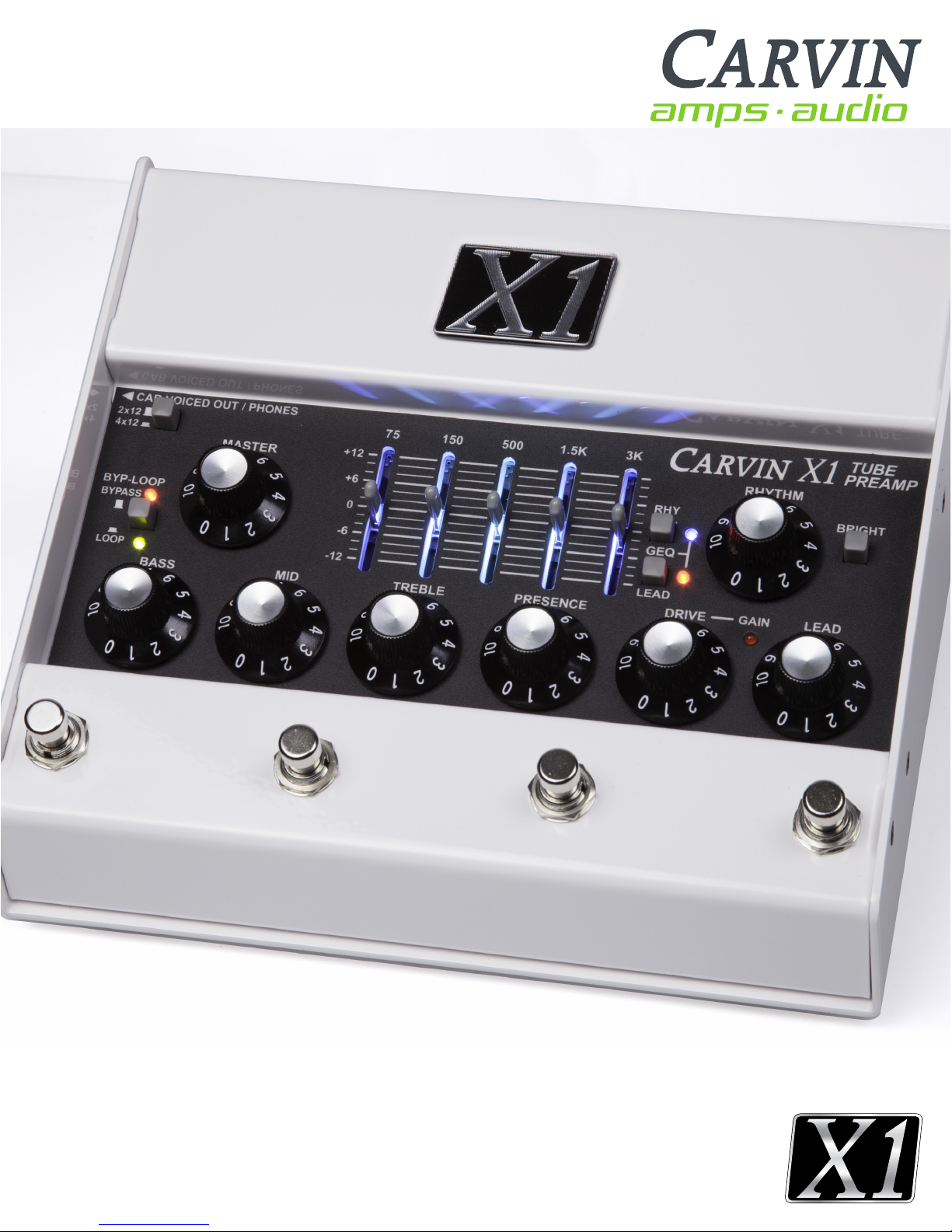
INTRODUCTION
Congratulations on your purchase of the X1 tube
preamp pedal. The X1 is designed to give you real
tube tone with the ability to integrate into nearly any
system. The X1 works as an add-in pedal to your
current setup, or it can be the center of your whole
guitar rig for live or recording. If you already have a
favorite guitar amp, the X1 preamp can work as a
pedal in front of your amp with true hardwire bypass.
It can feed a power amp or a guitar amp return to
power guitar speaker cabinets. If you don’t have an
amp at all, it can drive a regular guitar cabinet directly
with 1 Watt of power. The Cab Voiced/Phones jack
uses Carvin Amplifiers third generation
Cabinet Voicing circuit to give you the frequency
response of a 2x12” or 4x12” guitar speaker cabinet
so you can just plug in headphones or connect to
a recording or PA system without having to mic a
speaker.
DESIGNED FOR MAKING CONNECTIONS
The design criteria for the X1 was to deliver the
sounds of the classic Carvin X-100B amplifier in a
compact package with added connectivity. The result
is a full tube preamp in a pedal format, able to fit in
a carry-on or backpack. The X1 incorporates tube
technology with simple, yet flexible modern features
to interface with many types of gear.
EXTENSIVE TONE CONTROL
The wide range BASS, MID, TREBLE, and PRESENCE
tone controls are the same circuits as used in the
X-100B amplifier. The Rhythm channel’s
BRIGHT switch adds sparkling clear highs to clean
tones. The powerful 5-band Graphic EQ can be set to
activate for either or both channels, and footswitched
of f/o n .
WHAT, NO SPEAKERS?
The Phones jack uses Carvin Amp’s 3G (third
generation) analog Cabinet Voicing circuit to emulate
the response of a 2x12” or 4x12” guitar speaker cabinet.
Connect headphones for “silent” practice, or feed to any
combination of effects, recording inputs or live gear to
capture real tube tones without miking speakers.
WHAT, NO AMP ?
A 1 watt amp is built in, capable of driving any standard
guitar cabinet. 1 Watt is louder than you might think! Of
course it’s not enough for every situation, but it’s great
when you don’t want to carry an amp or when you
just want to practice.
12AX7 TUBE STAGES
Tone generation and overdrive comes from 12AX7
tubes, utilizing tube gain stages running at the same
operating conditions as they do in a full
size X100B tube amp.
GROUND CONTROL
The X1 has 4 top mounted footswitches for Channel,
Gain, Graphic EQ and Bypass. Switch from Rhythm
to Lead with the CHANNEL switch, then hit the GAIN
footswitch to kick up the tube overdrive when you
need it. Kick in the Graphic EQ for a second set of
tone on demand. Use the BYPLOOP footswitch to hard
bypass the whole pedal, or to just turn off the
Effects Loop. The Graphic EQ’s back lighting shows
different colors for channel selection and EQ on so
you always know what setting you’re on.
Page 3
CARVIN ENGINEERING DATA
X1
X1 TUBE PREAMP PEDALX1 TUBE PREAMP PEDAL
PG. 3
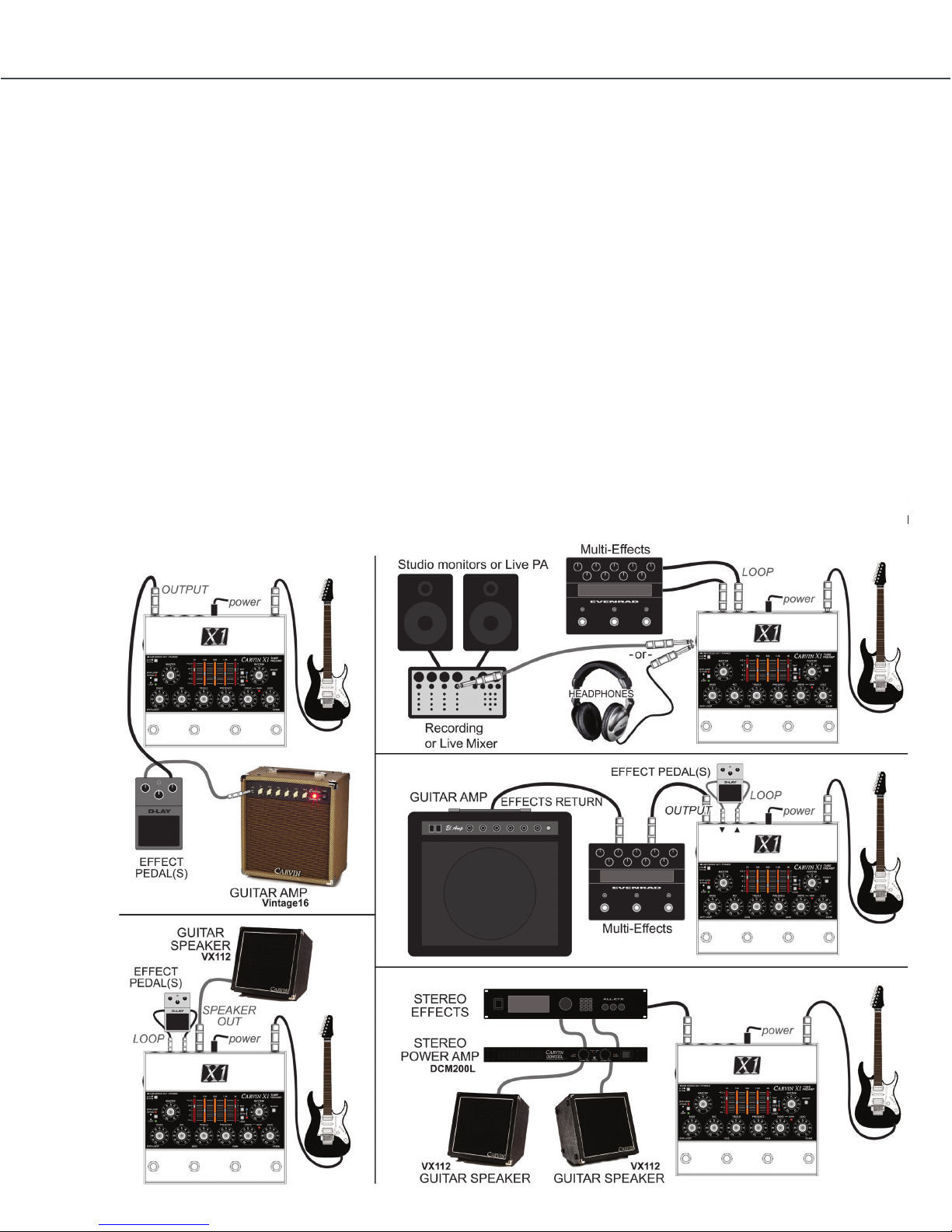
EXAMPLE SETUPS
The X1 works as an add-in pedal to your current setup, or it can be the center of your whole guitar rig for live
or recording. Feed a guitar amp input, or just use your amp’s power section. Drive a guitar cabinet from the
built-in 1 Watt amp.
Carvin’s analog Cabinet Voicing out emulates a guitar cabinet response for headphones,
recording or live gear.
X1 SPECIFICATIONS:
» Preamp Tubes: Two 12AX7 (four stages)
» Controls: MASTER, BASS, MID, TREBLE, PRESENCE,
GRAPHIC EQ
» Lead channel: VOLUME, DRIVE, GAIN switch
» Rhythm channel: VOLUME, BRIGHT switch
» Graphic EQ: 5-Band, channel tracking, foot
switchable, backlight color indications
» Audio connections: Input, Output, Loop Send, Loop
Return, Cab Voiced Out/Phones, Speaker
» Input Impedance: >500K Ohms
» Effects loop: Fully buffered, footswitchable,
pre-Master/Amp/Voiced Out. SEND level +4dBu
» Cab Voiced/Phones: 3G (3rd generation) active
analog circuit, 2x12” and 4x12” settings,
» TS (mono) or TRS dual-mono (for stereo headphones)
low impedance capable
» Speaker Output: 1 Watt @ 4 Ohms minimum
» Footswitches (4): BYPASS(Master or Loop), GEQ,
GAIN, CHANNEL
» Bypass type (master): relay engaged hardwire bypass
» DC adapter (included): , 100-240VAC input,
international plug set.. 12VDC/1A voltage regulated
output, 5.5mmOD/2.1mmID Center Positive
» Size: H x W x D 3.825” x 8.875” x 8.375” (97mm x
225mm x 213mm)
» Weight (without adapter): 3.9 lb. (1.77 kg)
EXAMPLE SETUPS
The X1 works as an add-in pedal to your current setup,
or it can be the center of your whole guitar rig for live
or recording. Feed a guitar amp input, or just use your
amp’s power section. Drive a guitar cabinet from the
built-in 1 Watt amp. Carvin Amp’s analog Cabinet
Voicing out emulates a guitar cabinet response for
headphones, recording or live gear.
Page 4

PG. 4
-
7. LEAD level control
Set the volume of the LEAD channel with this control. The MASTER
control also affects output.
8. DRIVE CONTROL (Lead channel)
The DRIVE control affects tube harmonics and saturation of the LEAD
channel. The GAIN function (see #10) increases the effect of the DRIVE.
For textured harmonics with mild tube overdrive, turn the DRIVE control
below “4”. For increased harmonics and sustain, turn up the DRIVE past
“6”. For full blown distortion, turn on the GAIN footswitch and set the
DRIVE control between “7” and “10”. If feedback occurs at high gain,
move the guitar pickups away from any speakers or reduce the DRIVE.
9. GAIN LED (Lead channel)
The red LED near the DRIVE control indicates GAIN mode is ON for
the LEAD channel, selected with the GAIN footswitch (middle-right).
The GAIN switch changes the gain structure of the LEAD channel:
With GAIN OFF, the DRIVE control has the range to go from a warm
clean sound, to a bluesy breakup, to a dynamic crunch overdrive.
GAIN ON increases the amount of drive available, allowing thick distortion
harmonics while still retaining 12AX7A tube dynamics. Hi-gain sounds are
available without the need for additional pedals that can limit dynamics.
10. GRAPHIC EQ and RHY & LEAD switches with LEDs
The Graphic Equalizer is powerful way to shape your sound. Each fader
can be set for up to 12dB of boost (slide up) or cut (slide down) for each
of the 5 frequency ranges labeled above.
To enable the Graphic EQ for the LEAD or RHYTHM cahnnel, use the
small “GEQ” switches to the right of the faders. ON is indicated by the
small blue LED (RHY channel) or small red LED (LEAD channel).
The Graphic EQ can be set ON or OFF independently for LEAD or
RHYTHM channels and switched from the (middle-left) “GEQ” footswitch.
The LED lighting in the fader slots will add YELLOW in the center area
when the Graphic EQ is ON.
11. BYP-LOOP SWITCH and LEDs
The small grey “BYP-LOOP” switch changes the BYPASS function of
the LEFT footswitch.
With the small switch OUT, pressing the LEFT footswitch engages full
BYPASS mode. Signal is passed from the Input jack directly to the outputs
unaffected by any of the controls. In BYPASS the CAB VOICED OUT/
PHONES jack will retain guitar speaker emulation. In BYPASS mode the
signal directly from the INPUT jack will be amplified at the SPEAKER
jack. The red “BYPASS” LED turns off when full BYPASS is enagaged.
With the small switch IN, pressing the LEFT footswitch bypasses only
15. LOOP SEND & RETURN JACKS and FOOTSWITCH
Use the SEND jack to connect to an effect’s Input. Use the RETURN
jack to connect to an effect’s Output.
To use the LEFT footswitch to bypass the effects LOOP, set the small
“BYP-LOOP” switch to IN for LOOP bypass mode. The green “LOOP”
LED is ON when the LOOP is active and OFF if the LOOP is bypassed.
Effects will be heard at the OUTPUT, SPEAKER and CAB VOICED jacks
unless full BYPASS or LOOP BYPASS is engaged (see #12).
Effects like compressor, envelope filter or wah pedals usually sound
best when used between the guitar and INPUT jack. Effects can also be
used on the OUTPUT or CAB VOICED OUT jacks.
16. OUTPUT
The rear panel OUTPUT jack is for connecting to guitar amps or power
amps which will drive guitar speakers.
The OUTPUT jack can be connected to the front input of a guitar amp
and added or removed from the signal path using the full BYPASS mode
of the LEFT footswitch similar to using a distortion pedal.
The OUTPUT jack can connect to a power amp input or to a guitar amp’s
“Effects Return” or “Power Amp In” to drive guitar speakers. Effects can
be connected between the OUTPUT and the amp or used in the LOOP.
SIDE PANEL
17. CAB VOICED OUT/PHONES JACK and 2x12/4x12 SWITCH
The side panel CAB VOICED OUT/PHONES jack uses Carvin’s third
generation active cabinet voicing circuit to emulate the response of a
guitar speaker cabinet. This allows you to perform or record tracks without
using guitar speakers. Select a 2x12” or 4x12” cabinet response with the
top panel 2x12-4x12 switch.
The CAB VOICED OUT/PHONES jack will drive recording gear, mixer
inputs, effects or power amps and will drive stereo headphones directly.
Lower the MASTER before plugging in. In BYPASS mode the cabinet
voicing remains active and gets signal directly from the INPUT jack,
unaffected by any controls.
HELP SECTION
A) As with any vacuum tubes in a metal chassis, the X1 chassis will
become warm. If the unit is functioning properly and sounding right this
is typically not a concern.
B) FEEDBACK FROM THE LEAD CHANNEL
The X1 may feedback when the VOLUME, DRIVE, TREBLE and
PRESENCE are turned all the way up. Like other high-gain tube amps,
REAR PANEL
X1 preamp CONNeCtIONS aND CONtrOLS
12 14 16
2
7
11
SIDE
PANEL
1
4
3
10
8
9
15
6
5
13
17
X1 CONNECTIONS AND CONTROLS
1. EQ LIGHTING - COLOR CHANGE
The LED lighting seen through the Graphic EQ’s vertical
slots changes color to indicate the Channel and Graphic
EQ selections. RED indicates the LEAD channel is
selected. BLUE indicates the RHYTHM channel is
selected. When the Graphic EQ is ON the LED lighting
inside the slots will add YELLOW in the center area,
ORANGE-YELLOW or BLUE-GREEN.
2. FOOTSWITCHES
The LEFT footswitch is for full BYPASS or effects LOOP
switching (see #11 for the BYP-LOOP selector switch).
The MIDDLE LEFT footswitch is for Graphic EQ
switching (see #10). The MIDDLE RIGHT footswitch
is for GAIN mode on the LEAD channel. The RIGHT
footswitch chooses between the LEAD or RHYTHM
channel.
The LEDs inside the Graphic EQ indicate which channel
is active.
3. MASTER
Set the MASTER control for overall volume for the
OUTPUT, SPEAKER, and PHONES/CAB VOICED OUT
jacks.
4. BASS, MID, TREBLE & PRESENCE (tone controls both channels)
You can start at 5 on the dial for each of the tone
controls. Set these controls according to the sound you
are looking for. Even though you may have found “your
sound”, you may want to change the settings for
different guitars or playing conditions. It’s normal to
decrease the BASS at higher playing levels, or adjust
the TREBLE or PRESENCE depending on the music.
Turning up PRESENCE allows you to stand out in the
mix or sound more aggressive. Turning PRESENCE
down produces a smoother, thicker sound.
5. RHYTHM level control
This control sets the RHYTHM channel volume. The
Rhythm channel gives you clean, crisp sounds with high
headroom. Special mud-cutting circuits allow clear and
vibrant guitar tones to come through. If unwanted
distortion is heard when using high output pickups,
lower this control and raise the MASTER control.
6. BRIGHT SWITCH (Rhythm channel)
The BRIGHT switch increases only the highest guitar
harmonics in the
upper frequency range. This is ideal for brightening up
dual coil pickups.
7. LEAD level control
Set the volume of the LEAD channel with this control.
The MASTER control also affects output.
QUICK START GUIDE
If you are like most players, you probably
want to plug in and get playing right away.
You can read the rest of the manual later to
learn the finer details. To get started you will need
your X1 preamp with it’s AC adapter, an instrument, a
standard guitar cord, and something to listen
with: an amp, headphones, or guitar
speaker. Turn the MASTER control to “0”. Turn the
Volume, Drive, and tone controls to their center position.
Plug in your instrument at the rear INPUT jack. If you are
using an amp with guitar speakers, plug in to the rear
OUTPUT jack. If you are listening with amplified fullrange speakers or headphones, plug into the side
PHONES/CAB VOICED OUT jack. A guitar speaker
can be plugged into the SPEAKER jack. Plug in the AC
adapter to the rear POWER jack, then plug it into the
proper AC voltage. Allow 30 seconds for the tubes to
warm up. Set the left ON/BYPASS footswitch to light
the red “ON” LED near the MASTER. The right
footswitch selects RHYTHM or LEAD channels. The
middle-right footswitch adds GAIN for the LEAD
channel. Turn up the MASTER slightly and adjust each
channel VOLUME. Adjust the DRIVE and tone controls
and you’re ready to go.
Page 5

CARVIN ENGINEERING DATACARVIN ENGINEERING DATA
X1X1
X1 TUBE PREAMP PEDALX1 TUBE PREAMP PEDAL
PG. 5
X1 CONNECTIONS AND CONTROLS CONT.
8. DRIVE CONTROL (Lead channel)
The DRIVE control affects tube harmonics and
saturation of the LEAD channel. The GAIN function (see
#10) increases the effect of the DRIVE. For textured
harmonics with mild tube overdrive, turn the DRIVE
control below “4”. For increased harmonics and sustain,
turn up the DRIVE past “6”. For full blown distortion,
turn on the GAIN footswitch and set the DRIVE control
between “7” and “10”. If feedback occurs at high gain,
move the guitar pickups away from any speakers or
reduce the DRIVE.
9. GAIN LED (Lead channel)
The red LED near the DRIVE control indicates GAIN
mode is ON for the LEAD channel, selected with
the GAIN footswitch (middle-right). The GAIN switch
changes the gain structure of the LEAD channel:
With GAIN OFF, the DRIVE control has the range to
go from a warm clean sound, to a bluesy breakup, to
a dynamic crunch overdrive. GAIN ON increases the
amount of drive available, allowing thick distortion
harmonics while still retaining 12AX7A tube dynamics.
Hi-gain sounds are available without the need for
additional pedals that can limit dynamics.
10. GRAPHIC EQ and RHY & LEAD switches with LEDs
The Graphic Equalizer is a powerful way to shape your
sound. Each fader can be set for up to 12dB of boost
(slide up) or cut (slide down) for each of the 5 frequency
ranges labeled above. To enable the Graphic EQ for
the LEAD or RHYTHM channel, use the small “GEQ”
switches to the right of the faders. ON is indicated by
the small blue LED (RHY channel) or small red LED
(LEAD channel). The Graphic EQ can be set ON or OFF
independently for LEAD or RHYTHM channels and
switched from the (middle-left) “GEQ” footswitch.
The LED lighting in the fader slots will add YELLOW in
the center area when the Graphic EQ is ON.
11. BYP-LOOP SWITCH and LEDs
The small grey “BYP-LOOP” switch changes the
BYPASS function of the LEFT footswitch.
With the small switch OUT, pressing the LEFT
footswitch engages full BYPASS mode. Signal is passed
from the Input jack directly to the outputs unaffected by
any of the controls. In BYPASS the CAB VOICED OUT/
PHONES jack will retain guitar speaker emulation.
In BYPASS mode the signal directly from the INPUT
jack will be amplified at the SPEAKER jack. The red
“BYPASS” LED turns off when full BYPASS is engaged.
With the small switch IN, pressing the LEFT footswitch
bypasses only the (Effects) LOOP. The green “LOOP”
LED is ON when the LOOP is active and shuts OFF
when the LOOP is bypassed.
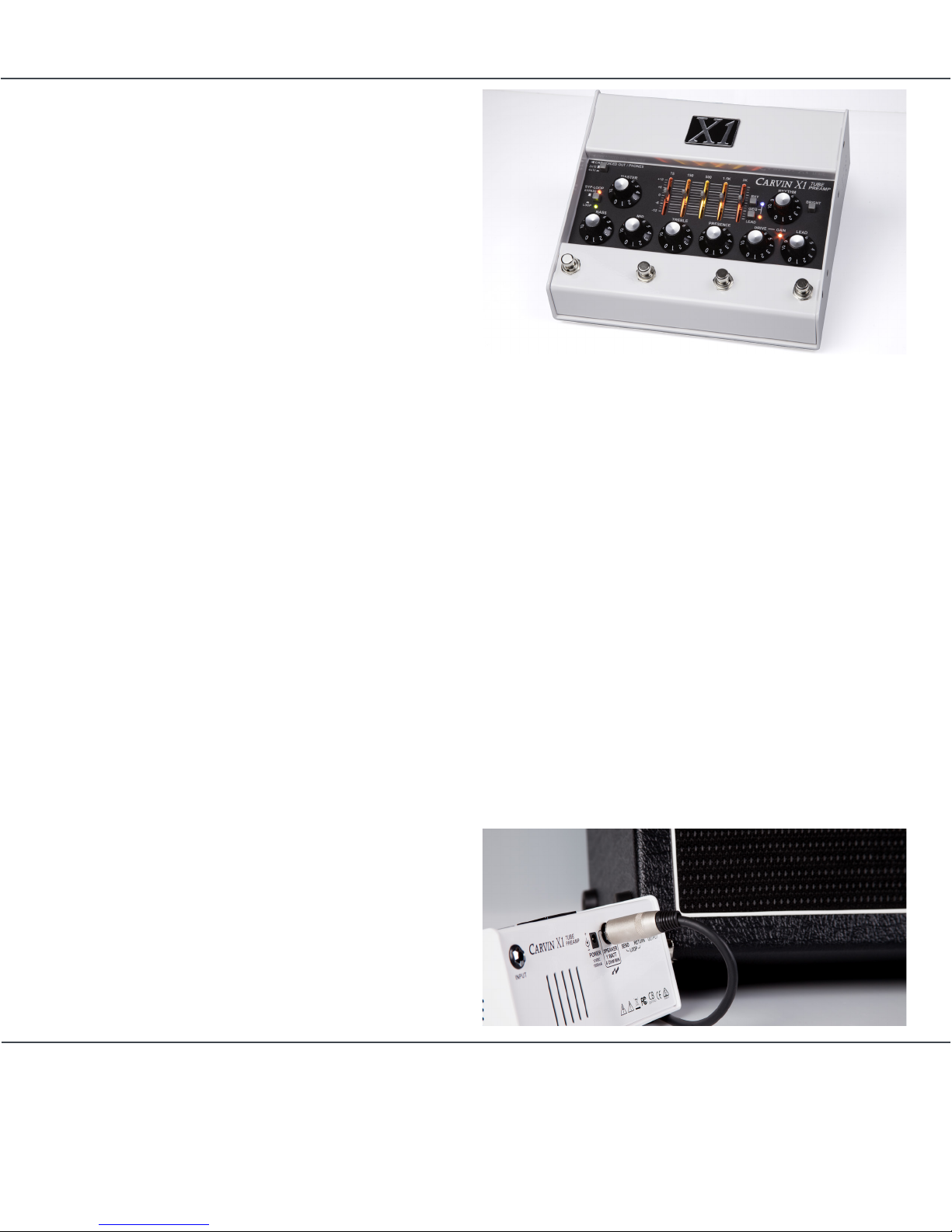
X1 REAR PANEL CONNECTIONS
12. INPUT
A standard 1/4” INPUT jack feeds the channels, or
bypasses directly to the outputs if BYPASS mode is
engaged. For best results, use a professional quality
guitar cord shorter than 25 feet. Typical cable
capacitance is about 25pF per foot. The longer the
cord, the greater the capacitance, which will reduce the
overall treble response from your guitar pickups.
13. POWER JACK
The POWER jack requires an AC adapter, which is
included with the X1 preamp. Other power sources can
be used, but must have a regulated 12VDC output, 1A
(1000mA) or more and center pin positive (+) polarity.
14. SPEAKER JACK
The SPEAKER jack can drive typical guitar speakers
directly. Multiple speakers can be connected as long as
the total impedance is not below 4 Ohms. For instance,
connecting two 8 ohms speakers in parallel equals a
4 Ohm impedance. In BYPASS mode the signal from
the INPUT jack will be amplified at the SPEAKER jack,
unaffected by any of the X1’s controls. The X1 will not
be harmed by playing without a speaker.
15. LOOP SEND & RETURN JACKS and FOOTSWITCH
Use the SEND jack to connect to an effect’s Input. Use
the RETURN jack to connect to an effect’s Output.
To use the LEFT footswitch to bypass the effects LOOP,
set the small “BYP-LOOP” switch to IN for LOOP bypass
mode. The green “LOOP” LED is ON when the LOOP is
active and OFF if the LOOP is bypassed. Effects will be
heard at the OUTPUT, SPEAKER and CAB VOICED jacks
unless full BYPASS or LOOP BYPASS is engaged (see
#12). Effects like compressor, envelope filter or wah
pedals usually sound best when used between the
guitar and INPUT jack. Effects can also be
used on the OUTPUT or CAB VOICED OUT jacks.
16. OUTPUT
The rear panel OUTPUT jack is for connecting to guitar
amps or power amps which will drive guitar speakers.
The OUTPUT jack can be connected to the front
input of a guitar amp and added or removed from the
signal path using the full BYPASS mode of the LEFT
footswitch similar to using a distortion pedal.
The OUTPUT jack can connect to a power amp input
or to a guitar amp’s “Effects Return” or “Power Amp
In” to drive guitar speakers. Effects can be connected
between the OUTPUT and the amp or used in the
LO O P.
Page 6

PG. 6
HELP SECTION
A) As with any vacuum tubes in a metal chassis, the
X1 chassis will become warm. If the unit is functioning
properly and sounding right this is typically not a
concern.
B) FEEDBACK FROM THE LEAD CHANNEL
The X1 may feedback when the VOLUME, DRIVE,
TREBLE and PRESENCE are turned all the way up.
Like other high-gain tube amps, this is normal. To
help control feedback and noise, reduce the DRIVE or
VOLUME, or move the guitar to the side or away from
the speakers. Sometimes replacing V1 or V2 (12AX7A
tubes) can help reduce feedback.
C) TUBE REPLACEMENT GUIDE
It is not uncommon for tubes to malfunction during
shipping or after a long period of time. The tubes may
need replacing if the sound becomes muddy, dull or
drops out.
-
7. LEAD level control
Set the volume of the LEAD channel with this control. The MASTER
control also affects output.
8. DRIVE CONTROL (Lead channel)
The DRIVE control affects tube harmonics and saturation of the LEAD
channel. The GAIN function (see #10) increases the effect of the DRIVE.
For textured harmonics with mild tube overdrive, turn the DRIVE control
below “4”. For increased harmonics and sustain, turn up the DRIVE past
“6”. For full blown distortion, turn on the GAIN footswitch and set the
DRIVE control between “7” and “10”. If feedback occurs at high gain,
move the guitar pickups away from any speakers or reduce the DRIVE.
9. GAIN LED (Lead channel)
The red LED near the DRIVE control indicates GAIN mode is ON for
the LEAD channel, selected with the GAIN footswitch (middle-right).
The GAIN switch changes the gain structure of the LEAD channel:
With GAIN OFF, the DRIVE control has the range to go from a warm
clean sound, to a bluesy breakup, to a dynamic crunch overdrive.
GAIN ON increases the amount of drive available, allowing thick distortion
harmonics while still retaining 12AX7A tube dynamics. Hi-gain sounds are
available without the need for additional pedals that can limit dynamics.
10. GRAPHIC EQ and RHY & LEAD switches with LEDs
The Graphic Equalizer is powerful way to shape your sound. Each fader
can be set for up to 12dB of boost (slide up) or cut (slide down) for each
of the 5 frequency ranges labeled above.
To enable the Graphic EQ for the LEAD or RHYTHM cahnnel, use the
small “GEQ” switches to the right of the faders. ON is indicated by the
small blue LED (RHY channel) or small red LED (LEAD channel).
The Graphic EQ can be set ON or OFF independently for LEAD or
RHYTHM channels and switched from the (middle-left) “GEQ” footswitch.
15. LOOP SEND & RETURN JACKS and FOOTSWITCH
Use the SEND jack to connect to an effect’s Input. Use the RETURN
jack to connect to an effect’s Output.
To use the LEFT footswitch to bypass the effects LOOP, set the small
“BYP-LOOP” switch to IN for LOOP bypass mode. The green “LOOP”
LED is ON when the LOOP is active and OFF if the LOOP is bypassed.
Effects will be heard at the OUTPUT, SPEAKER and CAB VOICED jacks
unless full BYPASS or LOOP BYPASS is engaged (see #12).
Effects like compressor, envelope filter or wah pedals usually sound
best when used between the guitar and INPUT jack. Effects can also be
used on the OUTPUT or CAB VOICED OUT jacks.
16. OUTPUT
The rear panel OUTPUT jack is for connecting to guitar amps or power
amps which will drive guitar speakers.
The OUTPUT jack can be connected to the front input of a guitar amp
and added or removed from the signal path using the full BYPASS mode
of the LEFT footswitch similar to using a distortion pedal.
The OUTPUT jack can connect to a power amp input or to a guitar amp’s
“Effects Return” or “Power Amp In” to drive guitar speakers. Effects can
be connected between the OUTPUT and the amp or used in the LOOP.
SIDE PANEL
17. CAB VOICED OUT/PHONES JACK and 2x12/4x12 SWITCH
The side panel CAB VOICED OUT/PHONES jack uses Carvin’s third
generation active cabinet voicing circuit to emulate the response of a
guitar speaker cabinet. This allows you to perform or record tracks without
using guitar speakers. Select a 2x12” or 4x12” cabinet response with the
top panel 2x12-4x12 switch.
The CAB VOICED OUT/PHONES jack will drive recording gear, mixer
X1 preamp CONNeCtIONS aND CONtrOLS
2
7
11
SIDE
PANEL
1
4
3
10
8
9
6
5
17
IMPOR TANT! FOR YOUR PROTE CTION , PLEA SE REA D THE FOLLOWI NG:
WATER AND MOISTU RE: App lianc e should n ot be use d near wate r (near a b athtub,
washbow l, kitc hen sink, laundry tu b, in a wet bas ement , or near a s wimming pool , etc).
Care sho uld be taken so that objects do not fall and l iquids are not spi lled into the
enclosure through openings.
POWER SOU RCES: The appl iance should be connec ted to a power s upply on ly of the
type
descri bed in the operating in struc tions o r as marke d on the un it.
GROUN DING OR POLARIZATIO N: Precautions should be taken s o that th e grounding or
polar izatio n means o f an appl iance is not defeated.
POWER CORD PROTECTIO N: Power su pply cords should b e routed so t hat they a re
not likely to be walke d on or pinched by items placed upo n or agai nst the m, payin g
particula r attention to cords at plugs , conveni ence rec eptacl es, and t he poin t where
they exit from the ap plian ce.
SERVICI NG: Th e user sh ould not at tempt to s ervi ce the unit beyond t hat desc ribed i n
the ope rating instructions. All ot her servici ng shou ld be refer red to qual ifie d service
personnel.
FUSING: If your u nit is eq uippe d with a fuse recept acle, rep lace on ly with th e same
type fuse. Refer to replac ement tex t on the u nit for co rrect fu se type .
MAINTAINING YOUR EQUIPMENT:
The outer surface of your un it can be w iped wi th a dry o r slightly damp cloth in order
to remove dus t and bri ng back the new loo k. Avoid sp illing liqu ids or allowing any
other fo reign mat ter inside the unit. As with all p ro gear, avoid prolonged use in c austi c
environments ( salt ai r). When us ed in such an environment, be sure the equipment is
adequately protected.
SERVICE:
In the USA, visit our webs ite: ww w.carv inaudio.com . O utside the USA: contact your
dea ler.
RISK OF E LECTR IC SHOC K
DO NOT OPE N
This sym bol is intended to
alert t he user to t he prese nce
of uninsulated “dangerous
voltage” within the product’s
enclosu re that may be of
sufficient magnitude to
constitute a risk o f
electr ic shock to persons.
This sym bol is intended to
alert t he user to t he prese nce
of important operating and
maintenance (servicing)
instructions in the literature
accompanying the appliance.
RISK OF E LECTR IC SHOC K
DO NOT OPE N
REFER SERVICING TO QUALIFIED
SERVICE PERSONNEL! CAUTION
THIS UNIT CONTAINS HIGH
VOLTAGE INSIDE!
1.) Disconnect the AC adapter from the X1.
- Do not apply power to the unit with the cover
removed! 2.) Remove the chrome nut on the left side
for “Phones/Cab Voiced Out”. 3.) Remove the 4 screws
on each side, and the 6 bottom screws. 4.) Remove the
bottom cover to view the two 12AX7 tubes.
5.) Carefully remove the old tubes with circular motion.
*If you can see cracks in the glass or feel the tube
coming apart as you move it, there may be broken
glass. Use a thick towel or thick gloves to remove the
tube. 6.) Check the replacement tubes for damage
to the glass and carefully straighten any bent pins if
needed. 7.) Carefully insert the new tubes. 8.) Place the
bottom cover back on the unit and screw in all screws.
9.) Install the chrome nut and washer on the side jack.
Done.
SIDE PANEL
17. CAB VOICED OUT/PHONES JACK and 2x12/4x12
SWITCH
The side panel CAB VOICED OUT/PHONES jack uses
Carvin Amplifier’s third generation active cabinet
voicing circuit to emulate the response of a
guitar speaker cabinet. This allows you to perform or
record tracks without using guitar speakers. Select
a 2x12” or 4x12” cabinet response with the top panel
2x12-4x12 switch. The CAB VOICED OUT/PHONES jack
will drive recording gear, mixer inputs, effects or power
amps and will drive stereo headphones directly.
Lower the MASTER before plugging in. In BYPASS
mode the cabinet voicing remains active and gets
signal directly from the INPUT jack, unaffected by any
controls.
Page 7

CARVIN ENGINEERING DATACARVIN ENGINEERING DATA
X1X1
X1 TUBE PREAMP PEDALX1 TUBE PREAMP PEDAL
PG. 7
Page 8

carvinaudio.com
X1 2 018 - 9 -10
 Loading...