

Page 1
CARVIN ENGINEERING DATA OPERATING MANUAL
The DCM Series professional amps are designed utilizing Carvin’s 35
years of experience in power amp technology. They meet or exceed every
standard for professional amplification. Their thick brushed anodized
aluminum face plates, large recessed knobs and heavy-duty steel chassis reflect the manufacturing quality within. All models carry the CE
approval for world-wide use.
PURE—TRANSPARENT SOUND
Carvin considers the sound of an amp equally important as its reliability. To
insure pure, uncolored sound, we designed one of the fastest responding power
amps on the market today. High slew rates of 45v/µs deliver superb transient
response. High frequencies are transparent and open—even at extreme levels.
Linear feedback circuits reduce distortion to near the theoretical zero limit, preventing any type of harshness which would lead to ear fatigue. The DCM Series
amps deliver flat, transparent, unaltered sound—especially important to the studio
user. And you can drive any type of reactive loads, including 70V transformer
distribution systems. These amps are designed to deliver non-stop, continuous
power and are completely protected from heat and short circuits.
ULTRA RUGGED FOR TOURING
Every chassis is made from heavy-duty 16 gauge steel that is plated before
being painted to prevent rust. All internal cabling is neatly tied and harnessed.
Every circuit card is FR-4 MILITAR Y SPEC, double-sided, through-hole plated,
fire retardant glass epoxy. This insures that the solder flows on the top, bottom
and through each hole of every component, preventing components from shaking loose—even through constant tour use. Neutrik™ XLR connectors,
heavy-duty power switches, recessed knobs, all give the DCM amps a “tanklike” ability to handle rough touring transport.
TOTALLY MODULAR
With the DCM Series, Carvin brings you totally modular construction. If you
ever need an I/O (input/output) connector card because a connector wore-out,
just unplug it and re-install the replacement card in minutes. You don’t have
to de-solder anything. This applies to every aspect of the DCM Series amps
including the power supply, power cards, heat sinks and fans. Everything is
connected by heavy-duty AMP™ and MOLEX™ type connectors for easy replacement—even the Toroid transformer is a total plug-in.
HEAVY-DUTY COOLING
Carvin offers up to 30% more cooling than comparable amps rated at the same
wattage. This means that the DCM Series are thermally “over-engineered” to be
sure heat will never be a concern. Even outdoor concerts in direct sunligdcm
will not cause thermal shut down. Carvin uses precision 6063 T-5 aluminum high
ratio heat sinks that are extruded for massive amounts of cooling. High efficiency ,
multi-speed fans cool your amp quietly even when moving air at up to 115 CFM!
LIGHTER WEIGHT
For some companies weight reduction means cost reduction. Carvin however,
uses expensive TOROID transformers to reduce weight. Toroids deliver massive amounts of “on demand” current for continuous 2 ohm operation. This
gives the power supply a solid foundation, yielding more headroom for the largest
subwoofer application. Not only do toroids deliver high current, but they are
known for reducing stray magnetic fields eliminating hum & noise. This is especially important for the recording industry.
DISTORTION-FREE LIMITERS
The purpose of a limiter is to hold down peaks so the amp won’t distort even
HT POWER AMP SPECIFICATIONS:
MODEL DCM600 DCM1000
Bridged RMS Continuous
4Ω, (20-20k Hz, <1.0%) 600w 1000w
8Ω, (20-20k Hz, <1.0%) 450w 700w
Both Channels RMS Continuous
2Ω (20-20k Hz, <1.0%) 300/300w 500/500w
4Ω (20-20k Hz, <1.0%) 250/250w 350/350w
8Ω (20-20k Hz, <1.0%) 125/125w 225/225w
THD (Typical—1/2 power): 0.03% 0.03%
Damping Factor: >350 >400
Slew Rate: bridged mode >45v/µs >45v/µs
Sensitivity: (4Ω, Vms) 1.0 V 1.0 V
Signal to Noise Ratio: Above 100dB
Frequency Response: ±0.5 dB, 20 Hz to 20kHz
(±1.5 dB, 10 Hz & 40 kHz)
Input Impedance: >20K Ω, balanced
Protection Circuits: Short Circuit • No Load Protection • SpeakerGuard™ • Thermal Shut-Off • Mute On/Off
Control and Indicators:
Front: Power switch • Recessed 41 detent attenuators • Signal LED • Clip LED • Protect LED • Power Indicator
Rear: Ground Lift (each channel) • Parallel Input Switch • Speaker Output Bridge Switch • Limiters
IN/OUT Switch • Input Connectors: Two each; Balanced XLR & 1/4” • Speaker Output Connectors:
Dual heavy-duty binding posts & two 1/4”
Dimensions: 3 1/2" High x 19" Wide x 10" Depth (2-space)
Net Weight: DCM600: 23 lbs. DCM1000: 26 lbs.
76-10000 0998
12340 World Trade Drive, San Diego, CA 92128
(619) 487-1600 (800) 854-2235
www.carvin.com
DCM600, DCM1000
For your records, you may wish to record the following information.
Serial No._____________________ Invoice Date_______________
RECEIVING INSPECTION—read before getting started
INSPECT YOUR UNIT FOR ANY DAMAGE which may have occurred during shipping. If any
damage is found, please notify the shipping company and CARVIN immediately.
SAVE THE CARTON & ALL P ACKING MATERIALS. In the event you have to re-ship your unit,
always use the original carton and packing material. This will provide the best possible protection during shipment. CARVIN and the shipping company are not liable for any damage caused
by improper packing.
SAVE YOUR INVOICE. It will be required for warranty service if needed in the future.
SHIPMENT SHORTAGE. If you find items missing, they may have been shipped separately.
Please allow several days for the rest of your order to arrive before inquiring.
RECORD THE SERIAL NUMBER on the enclosed warranty card or below on this manual
for your records. Keep your portion of the card and return the portion with your name and
comments to us.
DCM600, DCM1000 POWER AMPS
with extra hot input signals (this protects your expensive speakers). In addition,
a well designed limiter can increase your amp’s average output as much as 3 db.
Part of Carvin’s design uses the more expensive, distortion-free linear “opto isolators”. Unlike amps that use FET controlled limiters which can inject small amounts
of distortion, the DCM Series limiters keep your sound pure and uncolored!
FRONT PANELS & CONNECTING UP
The DCM Series feature front panel signal, peak and protect LEDs which let you
monitor the status of the amp. Both channels use precision 41 detent level controls
allowing you to see your settings at a glance. Balanced 1/4 phone & XLR input jacks
are used to eliminate hum & noise. Speaker outputs feature 1/4” jacks & heavyduty binding posts that accept up to 50 amp #7 speaker wires.
The rear professional accessory group offers a GROUND switch to remove the
chassis ground from the XLR input, a Parallel input switch connects the inputs of
both channels together eliminating Y connectors and allowing amp patching in multiple amp systems. The accessory group also features a bridge mode switch for
delivering full power into a 70V distribution system and a limiter ON/OFF switch
that gives you the choice of using the internal limiter circuitry.
Page 2
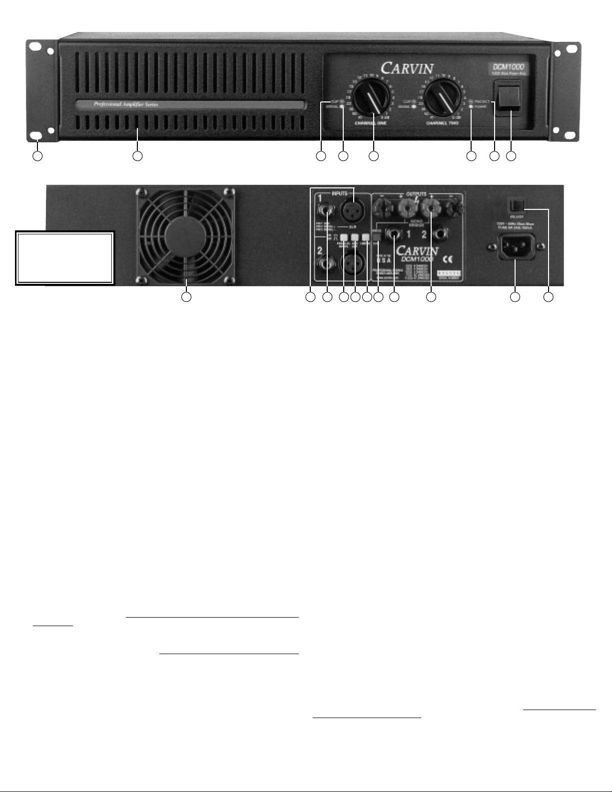
FRONT PANEL
1. MOUNTING
Sturdy one piece 12 guage steel face plate accomodates easy transporting along with facilitating rack
installation. The rack mounting holes are designed on ISO standard spacing. Four 10-32 x .5” phillip
machine screws are normally used to secure the amp. Rear support brackets are not required.
2. POWER SWITCH
Check the power amp connections and verify the AC line power source before engaging the POWER
switch. The yellow LED unmistakably indicates that all circuits are properly powered up. Yellow was
chosen so the operator could see the red indicators (clipping or protect) from a distance.
3. CHANNEL LEVEL CONTROL
A precision 41 step input LEVEL attenuate is used to adjust the volume levels. To deliver the amps maximum power without reducing the headroom of the signal source, the level controls should be tur ned full on.
4. CHANNEL SIGNAL INDICATOR
The green SIGNAL LED indicators will start to flash when there is a signal passing to your speakers (-30dBM).
This lets you know when the amp is passing a signal to your rear speaker connectors.
5. CHANNEL CLIP INDICATOR
The red CLIP LED indicators will start to flash when each channel has reached its maximum output. Occasional
flashing caused by lower bass frequencies is OK. However, consistent flashing caused from higher frequencies
may damage high frequency drivers (excessive distortion). This does not cause damage to the amp.
6. FRONT COOLING VENTS/FAN
Upon rack installation, the rear of the amp must be fully exposed to room temperature air. The surrounding air should not be warmer than 120° or the thermal protection could active the PROTECT LED.
The front cooling vents are not to be restricted from exhausting the warm air.
7. PROTECT LED INDICATOR
The red PROTECT LED provides the operator with information about the status of the amplifier. The
PROTECT LED can come on under 3 different conditions (when this happens both channels are muted
by disconnecting the output speaker relays protecting your speakers);
1) During power-up, the amplifier stays in a muted state for approx. 3 sec until it determines that
everything is functioning normally (no output shorts or over temp conditions).
2) When the output load draws excessive current or a direct short is detected caused by a shorted
speaker cable or speaker system. Reset this condition by tur
ning the amp off for two seconds and
then on again. Check for shorted cables and the total speaker system impedance connected to
each channel (2 ohms minimum per ch or 4 ohms BRIDGED).
3) Overheating is usually determined when the amp stops in the middle of a performance and the
PROTECT LED comes on. If this is the cause, leave the amp on for the fan to cool the amp down.
The amp will automatically reset within 1 to 3 minutes. The PROTECT LED will turn off when
ready. Check for the following conditions; a) The rear intake air is restricted, b) The intake air is
extremely warm, c) The front exhaust vents are restricted, or d) Excessive speaker load (try other
speakers or remove speakers if you have more than one connected to each channel). Again, the
minimum impedance is 2 ohms per ch or 4 ohms BRIDGED)
REAR PANEL
8. XLR CHANNEL INPUTS
For most professional applications, use the XLR balanced inputs. This will help to reduce hum and allow
of longer cable runs from your signal source (mixer, etc). Because this is a balanced input, the gain will
be 6 dB higher than using the 1/4” input jack with non balanced lines. XLR pin configuration: Pin 1: Grounded
through the GROUND LIFT switch, Pin 2: positive Bal. signal and Pin 3: negative Bal. signal.
9. CHANNEL 1/4” PHONE JACK INPUT
This stereo phone jack is designed to receive either balanced or unbalanced input signals. Balanced signals coming into this jack should be wired with the connector’s tip going to signal + and the connector’s
ring to signal -. The connector’s sleeve is then tied internally to ground through the GROUND LIFT switch.
10. PARALLEL OR “Y” INPUTS
The rear PARALLEL switch allows you to drive both channels from either input. All signals entering any
input will be available on both channels. This eliminates Y adapter cables. This feature is used to “daisy
chain” one piece of equipment to another. Just plug into the unused INPUT (1/4” or XLR) and it will
become an output for other equipment.
11. INPUT GROUND LIFT
Many times sound systems are connected in such a manner to cause a grounded loop with the inputs
that result in audible hum. The input GND LIFT (1/4” & XLR) switch on the rear panel will help eliminate
this problem. If not, another way to eliminate ground loops is to install a “line matching” transformer
between the amplifier input and the signal source and then cutting the ground wire to PIN 1.
12. LIMITERS
To activate the LIMITERS, engage the rear limiter switch. The built-in high quality limiters are recommended
to hold down peaks that could cause early distortion. Limiters will help to rise the average power so that
you can get more output from each channel. To check the effectiveness of the limiters when the channel
starts to distort (under the amps full output), engage the limiters and hear the reduction of the distortion.
If the distortion stops, you can turn the channel up for more power. The lower bass frequencies are most
affected. WARNING: Do not check in an environment where the sound level could damage your ears!
13. SPEAKER OUTPUTS
The standard 1/4” SPEAKER jacks are used for lower power applications. Turn the amp off before con-
necting your speakers.
14. SPEAKER BINDING POSTS
For high power speaker connections, use the rear BINDING POSTS to connect your speakers. Wire sizes up
to 7 gauge (50 amps) can be inserted into the binding post “side holes”. Larger cable can be used with “banana”
plugs which plug into the end of the binding posts (remove colored caps). Binding posts are spaced on ISO
standards. Use the two center RED binding posts for BRIDGE speaker connections (see 15 BRIDGE MODE).
15. BRIDGE MODE—
25V/70V DISTRIBUTION SYSTEMS
The “DCM” Series can be operated in bridge mode if you require a 25V / 70V distribution speaker system
or a high powered mono (single channel) amp. With your amp off, push in the rear (recessed) BRIDGE switch
after you have made your speaker connections to the rear center RED binding posts (ch 1 is + and ch 2 is ). No other speaker connectors or binding posts can to be used at the same time!”. The INPUT and LEVEL
is handled by channel 1. Channel 2 is non-operational. The minimum speaker impedance is 4 ohms or a 25V
distribution line. CAUTION: The power developed by bridging your amp can destroy most speaker systems!
16. AC POWER
Your amp is designed to run on either 120V 60 Hz or 230V 50Hz depending on the model purchased.
The voltage range for 120V model is 95V to 132V and for 230V model it is 195V to 253V . The rear heavyduty AC receptacle will accept a standard grounded AC cord that is designed your country. Be sure to
check your power source before plugging into a grounded (3 prong) outlet. Never defeat the grounded
connection or electrocution may result! Firmly push the AC cord all the way into its recepticle.
17. AC CIRCUIT BREAKER
We have provided a circuit breaker so that you will never have to replace the fuse. Occasionally the
circuit breaker on your amp may have to be reset if high AC voltage surges are present or if the amp is
used with excessive loads. See “Helpful Hints”.
221 3456
FRONT & REAR PANEL CONTROLS
7
6 1610 11 12 15 14 1798 13
WARNING
This product produces high
sound pressure levels that
could damage your hearing.
Use with caution.
Page 3

STEREO OR BALANCED SIGNAL LINE
GND
- SIGNAL (REC.)
+ SIGNAL (SEND)
RING
SLEEVE
RING
TIP
TIP
TYPICAL STEREO SETUP*
(OR MONO BI-AMP)
STEREO BIAMPING*
120V 60Hz Slow Blow
FUSE 8A 3AG 700VA
www.carvin.com
MADE
AUS
INTHE
SERIAL NUMBER
8 OHMS/CH
4 OHMS/CH
2 OHMS/CH
8Ω BRIDGED
4Ω BRIDGED
175W
250W
375W
500W
750W
INPUTS
1
2
MONO
BRIDGE
— + + —
OUTPUTS
1 2
PARALLEL
INPUTS
LIMITER
XLR
GND
LIFT
CH1
PIN 2 SIGNAL +
PIN 3 SIGNAL –
PIN 1 GND
The channel PARALLEL switch OFF (OUT).
25V or 70V
Distribution System:
Wattage of transformer (TAP)
divided by total wattage
of Amp = Number of
transformer/speaker(s)
that can be hooked up.
or
To signal socket XLR or 1/4" 2 or 3 cond. shielded
Activate the BRIDGE switch
(IN). Control the level by Ch 1
( Ch 2 does not function.
Ch 1 Input
+
16
8
4
C
or
Single speaker or
system connected
in BRIDGE mode.
Minimum imp. 4Ω
15w
7w
3w
1w
C
+
16
8
4
C
15w
7w
3w
1w
C
120V 60Hz Slow Blow
FUSE 8A 3AG 700VA
www.carvin.com
MADE
AUS
INTHE
SERIAL NUMBER
8 OHMS/CH
4 OHMS/CH
2 OHMS/CH
8Ω BRIDGED
4Ω BRIDGED
175W
250W
375W
500W
750W
INPUTS
1
2
MONO
BRIDGE
— + + —
OUTPUTS
1 2
PARALLEL
INPUTS
LIMITER
XLR
GND
LIFT
CH1
PIN 2 SIGNAL +
PIN 3 SIGNAL –
PIN 1 GND120V 60Hz Slow Blow
FUSE 8A 3AG 700VA
www.carvin.com
MADE
AUS
INTHE
SERIAL NUMBER
8 OHMS/CH
4 OHMS/CH
2 OHMS/CH
8Ω BRIDGED
4Ω BRIDGED
175W
250W
375W
500W
750W
INPUTS
1
2
MONO
BRIDGE
— + + —
OUTPUTS
1 2
PARALLEL
INPUTS
LIMITER
XLR
GND
LIFT
CH1
PIN 2 SIGNAL +
PIN 3 SIGNAL –
PIN 1 GND
Low Amplifier
Left
Highs
PHASE
MADE
AUS
INTHE
INPUT
XC3000
Electronic Crossover
IN
OUT
CHANNEL TWO CHANNEL ONE
LOW OUT MID OUT HIGH OUT LOW OUT MID OUT HIGH OUT
LOW OUT
SUM
INPUT
IN
OUTINOUT
IN
OUTINOUTINOUT
PHASE PHASE PHASE PHASE PHASE
CH 1/2
50-60Hz 20VA
120V 240V
Suggested Crossover settings
Low/High 1k-2.5k Hz
Crossover
Input
High Amplifier
Right
Lows
Left
Lows
Right
Highs
Left
Highs
High Amplifier
Left
Mids
Left
Lows
Right
Highs
Right
Lows
Right
Mids
Mid Amplifier
Low Amplifier
PHASE
MADE
AUS
IN
TH
E
INPU
T
Electronic Crossover
IN
OUT
CHANNEL TWO CHANNEL ONE
LOW OUT MID OUT HIGH OUT LOW OUT MID OUT HIGH OUT
LOW OUT
SUM
INPUT
IN
OUTINOUTINOUTINOUTINOUT
PHASE PHASE PHASE PHASE PHASE
CH 1/2
50-60Hz
20VA
120V 240V
Mixer Output
Crossover
Input
120V 60Hz Slow Blow
FUSE 8A 3AG 700VA
MADE
AUS
INTHE
SERIAL NUMBER
8 OHMS/CH
4 OHMS/CH
2 OHMS/CH
8Ω BRIDGED
4Ω BRIDGED
175W
250W
375W
500W
750W
INPUTS
1
2
MONO
BRIDGE
–+ +–
OUTPUTS
12
PARALLEL
INPUTS
LIMITER
XLR
GND
LIFT
CH1
PIN 2 SIGNAL +
PIN 3 SIGNAL –
PIN 1 GND
120V 60Hz Slow Blow
FUSE 8A 3AG 700VA
MADE
AUS
INTHE
SERIAL NUMBER
8 OHMS/CH
4 OHMS/CH
2 OHMS/CH
8Ω BRIDGED
4Ω BRIDGED
175W
250W
375W
500W
750W
INPUTS
1
2
MONO
BRIDGE
–+ +–
OUTPUTS
12
PARALLEL
INPUTS
LIMITER
XLR
GND
LIFT
CH1
PIN 2 SIGNAL +
PIN 3 SIGNAL –
PIN 1 GND
120V 60Hz Slow Blow
FUSE 8A 3AG 700VA
www.carvin.com
MADE
AUS
INTHE
SERIAL NUMBER
8 OHMS/CH
4 OHMS/CH
2 OHMS/CH
8Ω BRIDGED
4Ω BRIDGED
175W
250W
375W
500W
750W
INPUTS
1
2
MONO
BRIDGE
–+ +–
OUTPUTS
12
PARALLEL
INPUTS
LIMITER
XLR
GND
LIFT
CH1
PIN 2 SIGNAL +
PIN 3 SIGNAL –
PIN 1 GND
Suggested Crossover settings
Low/Mid 100-200Hz
Mid/High 1k-2k Hz
120V 60Hz Slow Blow
FUSE 8A 3AG 700VA
www.carvin.com
MADE
AUS
INTHE
SERIAL NUMBER
8 OHMS/CH
4 OHMS/CH
2 OHMS/CH
8Ω BRIDGED
4Ω BRIDGED
175W
250W
375W
500W
750W
INPUTS
1
2
MONO
BRIDGE
— + + —
OUTPUTS
1 2
PARALLEL
INPUTS
LIMITER
XLR
GND
LIFT
CH1
PIN 2 SIGNAL +
PIN 3 SIGNAL –
PIN 1 GND
Full Range
(Lo Freq. Bi-Amp)
Woofer System
For channel separation (stereo)
or Bi-Amping the PARALLEL
switch must be OFF (OUT).
Full Range
(Hi Freq. Bi-Amp)
Horn System
(Hi Freq. Bi-Amp)
(Lo Freq. Bi-Amp)
Ch 1 Left
Ch 2 Right
BRIDGE switch
must be OFF (OUT).
or
25V OR 70V DISTRIBUTION SYSTEM
SHIELD
+POS.
2
1
3
-NEG.
SHIELD
+POS.
2
1
3
-NEG.
GND
- SIGNAL (BAL.)
+ SIGNAL (BAL.)
BALANCED MIC/LINE
(Shielded)
SPEAKER OR SIGNAL LINE CABLE
(Shielded or Unshielded)
SLEEVE
SLEEVE
TIP
TIP
* For monural (mono) systems, depress the PARALLEL button (IN) and only use CHANNEL 1 input (speaker hookup identical to stereo). Mono is normally recommended for live stage applications. Live stereo sounds great in the center of the
audience, however, the audience on one side will not hear the program material presented on the other side.
HELPFUL HINTS
speaker connector only and your bass response will improve.
6) THE AMP’S REAR CIRCUIT BREAKER TRIPS: When the red
CLIP LEDs are flashing at 2Ω (4Ω bridged), the rear circuit
breaker may trip. This is normal. Reset breaker & reduce level.
7) MAIN AC BREAKER TRIPS: Each high powered amp may require
a separate 20 amp circuit breaker (230V: 10 amp) for delivering
full power. Note: Some 120V homes have only 15 amp br eakers.
1) NO SOUND FROM CH 2: The rear BRIDGE switch has been
inadvertently pushed in.
2) STEREO CHANNELS SOUND THE SAME: The rear
PARALLEL switch has been inadvertently pushed in.
3) NO HIGH FREQUENCIES: T weeters or midrange drivers have
been damaged or blown from feedback or overpowering.
4) SYSTEM HUM: Try switching the GND LIFT switch IN or OUT
(depending on your use). If hum is not eliminated, then use a 600Ω
line input transformer cutting the input ground on the connectors
(Pin 1). This isolates the input ground from the AC power ground
eliminating a system ground loop.
5) POOR SOUND (BASS): The speaker systems are wired out
of phase to each other. To correct, reverse the wires on one
SHIELD (GROUND)
+ TIP (POS. SIGNAL)
STEREO TRIAMPING*
DCM1000
DCM1000
DCM1000
DCM1000
DCM1000
DCM1000
Page 4

Parts list for DCM Series Power Amplifiers Carvin P/N
Binding Post, 2-way, Red/Black.................................................03-10450
Cover, Black 18GA Steel............................................................10-82005
Chassis......................................................................................10-07509
Face panel..................................................................................10-07503
Face panel bezel.........................................................................10-07504
Trim Label..................................................................................77-07521
Fan, 24VDC 80mm.....................................................................70-02408
Fan Guard, 80x80mm................................................................03-90080
Power cord (120V)....................................................................05-01603
Power cord (230V)....................................................................05-01903
Handle, 2-space rack.................................................................10-11120
Knob, Black, recessed................................................................07-09011
Power cord, 8’2”........................................................................05-01603
Stand-off, Al, 1.5” Hex, 6-32......................................................03-63315
Toroid insulator pad 3.8” OD.....................................................03-15004
DCM600 Specific parts:
Label Face..................................................................................77-07522
Rear label ..................................................................................77-07508
10 Amp Circuit breaker (120V)..................................................70-28110
6 Amp Circuit breaker (230V)....................................................70-28106
Toroid, 120V..............................................................................15-70160
Toroid, 230V..............................................................................15-70260
C1, Capacitor 10KµF 63V, Poly 20%.........................................42-10363
C2B, Capacitor 10KµF 63V, Poly 20%.......................................42-10363
R30, 1/4W Resistor 47K, .35” prep. 5% Carbon......................50-47045
DCM1000 Specific parts:
Label Face..................................................................................77-07523
Rear label...................................................................................77-07510
15 Amp Circuit breaker (120V)..................................................70-28115
10 Amp Circuit breaker (230V)..................................................70-28110
Toroid, 120V..............................................................................15-10166
Toroid, 230V..............................................................................15-10266
C1, Capacitor 10KµF 80V, Poly 20%.........................................42-10381
C2, Capacitor 10KµF 80V, Poly 20%.........................................42-10381
R21, 1/4W Resistor 36K, .35” prep. 5% Carbon......................50-36045
Parts list for PCB Card HT Series Power Amplifiers Carvin P/N
Ref. Des. Description Carvin P/N
A1 IC Op Amp NE5532 Linear Output 60-55320
A2 IC Op Amp MC4558 CP1 Dual HFREQ 60-45580
A3 IC Op Amp NE5532 Linear Output 60-55320
A4 IC Op Amp NE5532 Linear Output 60-55320
A5 IC Op Amp MC4558 CP1 Dual HFREQ 60-45580
A6 IC Op Amp MC4558 CP1 Dual HFREQ 60-45580
A7 IC Op Amp MC4558 CP1 Dual HFREQ 60-45580
A8 IC Op Amp NE5532 Linear Output 60-55320
BP1 Binding Post Red/Black Combo 03-10400
BP2 Binding Post Red/Black Combo 03-10400
BR1 Diode Bridge AC/DC PCB MTG 60-35041
C3 Capacitor 1000µF 35V Electrolytic 20% 47-10235
C4 Capacitor 1000µF 35V Electrolytic 20% 47-10235
C5 Capacitor 0.047µF 100V Poly 10% 46-47312
C6 Capacitor 0.047µF 100V Poly 10% 46-47312
C7 Capacitor 220µF 50V Electrolytic 20% 47-22151
C8 Capacitor 10µF 50V Electrolytic 20% 47-10051
C9 Capacitor 0.047µF 100V Poly 10% 46-47312
C10 Capacitor 0.047µF 100V Poly 10% 46-47312
C11 Capacitor 0.047µF 100V Poly 10% 46-47312
C15 Capacitor 0.047µF 100V Poly 10% 46-47312
C16 Capacitor 0.047µF 100V Poly 10% 46-47312
C17 Capacitor 0.047µF 100V Poly 10% 46-47312
C18 Capacitor 470µF 25V Electrolytic 20% 47-47125
C100 Capacitor 27PF 500V Ceramic 5% 45-27052
C101 Capacitor 27PF 500V Ceramic 5% 45-27052
C102 Capacitor 22µF 50V Electrolytic 20% 47-22051
C104 Capacitor 27PF 500V Ceramic 5% 45-27052
C105 Capacitor 0.047µF 100V Poly 10% 46-47312
Ref. Des. Description Carvin P/N
C110 Capacitor 0.001µF 100V Poly 10% 46-10212
C111 Capacitor 22µF 50V Electrolytic 20% 47-22051
C115 Capacitor 27PF 500V Ceramic 5% 45-27052
C116 Capacitor 56PF 500V Ceramic 5% 45-56052
C117 Capacitor 120PF 500V Ceramic 5% 45-12052
C118 Capacitor 10µF 63V Electrolytic 20% 47-10061
C119 Capacitor 0.047µF 100V Poly 10% 46-47312
C120 Capacitor 0.001µF 100V Poly 10% 46-10212
C121 Capacitor 0.068µF 100V Poly 10% 46-68312
C200 Capacitor 27PF 500V Ceramic 5% 45-27052
C201 Capacitor 27PF 500V Ceramic 5% 45-27052
C202 Capacitor 22µF 50V Electrolytic 20% 47-22051
C204 Capacitor 27PF 500V Ceramic 5% 45-27052
C205 Capacitor 0.047µF 100V Poly 10% 46-47312
C210 Capacitor 0.001µF 100V Poly 10% 46-10212
C211 Capacitor 22µF 50V Electrolytic 20% 47-22051
C215 Capacitor 27PF 500V Ceramic 5% 45-27052
C216 Capacitor 56PF 500V Ceramic 5% 45-56052
C217 Capacitor 120PF 500V Ceramic 5% 45-12052
C218 Capacitor 0.047µF 100V Poly 10% 46-47312
C219 Capacitor 0.047µF 100V Poly 10% 46-47312
C220 Capacitor 0.001µF 100V Poly 10% 46-10212
C221 Capacitor 0.068µF 100V Poly 10% 46-68312
D1 Diode 1N4003 Rect Gen 1A 200V 60-40030
D2 Diode 1N4003 Rect Gen 1A 200V 60-40030
D3 Diode 1N4003 Rect Gen 1A 200V 60-40030
D4 Diode 1N4003 Rect Gen 1A 200V 60-40030
D5 Diode 1N4003 Rect Gen 1A 200V 60-40030
D6 Diode 1N4003 Rect Gen 1A 200V 60-40030
D7 Diode 1N4003 Rect Gen 1A 200V 60-40030
D8 LED Red small #204HD 3mm T-1.0 60-75320
D9 LED Yellow small #204YD 3mm T-1.0 60-75340
D10 Diode 1N4003 Rect Gen 1A 200V 60-40030
D11 Diode 1N4003 Rect Gen 1A 200V 60-40030
D12 Diode 1N4003 Rect Gen 1A 200V 60-40030
D13 Diode 1N4003 Rect Gen 1A 200V 60-40030
D100 Diode 1N4003 Rect Gen 1A 200V 60-40030
D101 Diode 1N4003 Rect Gen 1A 200V 60-40030
D102 LED Green small #204GD 3mm T-1.0 60-75330
D103 LED Red small #204HD 3mm T-1.0 60-75320
D104 LED Red small #204HD 3mm T-1.0 60-75320
D106 Diode 1N4003 Rect Gen 1A 200V 60-40030
D107 Diode 1N4003 Rect Gen 1A 200V 60-40030
D108 Diode 1N4003 Rect Gen 1A 200V 60-40030
D109 Diode 1N4003 Rect Gen 1A 200V 60-40030
D200 Diode 1N4003 Rect Gen 1A 200V 60-40030
D201 Diode 1N4003 Rect Gen 1A 200V 60-40030
D202 LED Green small #204GD 3mm T-1.0 60-75330
D203 LED Red small #204HD 3mm T-1.0 60-75320
D204 LED Red small #204HD 3mm T-1.0 60-75320
D205 Diode 1N4003 Rect Gen 1A 200V 60-40030
D206 Diode 1N4003 Rect Gen 1A 200V 60-40030
D207 Diode 1N4003 Rect Gen 1A 200V 60-40030
D208 Diode 1N4003 Rect Gen 1A 200V 60-40030
D209 Diode 1N4003 Rect Gen 1A 200V 60-40030
H1-A Header 4 Pin AMP 9A 600V PCB MTG 23-08604
H1-B Header 4 Pin AMP 9A 600V PCB MTG 23-08604
H2 Header 2 Pin Vert Panduit PCB MTG 23-10002
H2-A Header 4 Pin Vert SHS 2.5mm PCB MTG 23-11004
H2-B Header 4 Pin Vert SHS 2.5mm PCB MTG 23-11004
H3-A Header 10 Pin Vert SHS 2.5mm PCB MTG 23-11010
H3-B Header 10 Pin Vert SHS 2.5mm PCB MTG 23-11010
H4-A Header 10 Pin Vert SHS 2.5mm PCB MTG 23-11010
H4-B Header 10 Pin Vert SHS 2.5mm PCB MTG 23-11010
H5 Header 2 Pin Vert Panduit PCB MTG 23-10002
H6-A Header 4 Pin AMP 9A 600V PCB MTG 23-08604
H6-B Header 4 Pin AMP 9A 600V PCB MTG 23-08604
H7 Header 9 Pin AMP 9A 600V PCB MTG 23-08609
J100 XLR Jack Female Neutrik Vert PCB MTG 21-40000
J101 Phone Jack, 1/4” 7 Pin Plastic, 24mm Tall 21-06457
J102 Phone Jack, 1/4” 3 Pin Plastic, 24mm Tall 21-06453
J200 XLR Jack Female Neutrik Vert PCB MTG 21-40000
J201 Phone Jack, 1/4” 7 Pin Plastic, 24mm Tall 21-06457
J202 Phone Jack, 1/4” 3 Pin Plastic, 24mm Tall 21-06453
Ref. Des. Description Carvin P/N
K100 Relay 24V12A SPDT SIEMENS PCB MGT 70-05712
K200 Relay 24V12A SPDT SIEMENS PCB MGT 70-05712
L100 Inductor 3.3µH Air Core Spool 15-00165
L200 Inductor 3.3µH Air CoreSpool 15-00165
OP1 Opto Isolator VTL5C2 60-50253
OP2 Opto Isolator VTL5C2 60-50253
P100 Pot. B10Kx2 41Clk Brkt Rot Knurled 90° 71-10301
P101 Pot. Trimmer 5K Vert PCB MTG 71-25000
P200 Pot. B10Kx2 41Clk Brkt Rot Knurled 90° 71-10301
P201 Pot. Trimmer 5K Vert PCB MTG 71-25000
Q1 Transistor Darlington NPN MPSA14 60-00014
Q2 Transistor 2N5400 PNP AMP TO-92 60-54000
Q100 Transistor Darlington NPN MPSA14 60-00014
Q101 Transistor TIP31C 3A 100V NPN TO-220 60-31000
Q102 Transistor MPSW42 HV 1.0W NPN T0-237 60-00042
Q103 Transistor CENW92 HV PNP 1.0W TO-92 60-00092
Q104 Transistor TIP32C 3A 100V PNP TO-220 60-32000
Q105 Transistor TIP31C 3A 100V NPN TO-220 60-31000
Q106 Transistor TIP31C 3A 100V NPN TO-220 60-31000
Q107 Transistor MJL21194 NPN 16A 250V 200W 60-21194
Q108 Transistor MJL21194 NPN 16A 250V 200W 60-21194
Q109 Transistor MJL21193 PNP 16A 250V 200W 60-21193
Q110 Transistor MJL21193 PNP 16A 250V 200W 60-21193
Q200 Transistor Darlington NPN MPSA14 60-00014
Q202 Transistor MPSW42 HV 1.0W NPN T0-237 60-00042
Q203 Transistor CENW92 HV PNP 1.0W TO-92 60-00092
Q204 Transistor TIP32C 3A 100V PNP TO-220 60-32000
Q205 Transistor TIP31C 3A 100V NPN TO-220 60-31000
Q206 Transistor TIP31C 3A 100V NPN TO-220 60-31000
Q207 Transistor MJL21194 NPN 16A 250V 200W 60-21194
Q208 Transistor MJL21194 NPN 16A 250V 200W 60-21194
Q209 Transistor MJL21193 PNP 16A 250V 200W 60-21193
Q210 Transistor MJL21193 PNP 16A 250V 200W 60-21193
R1 1/4W Resistor 2.2K .35” prep. 5% Carbon 50-22035
R2 1/4W Resistor 3.3K .35” prep. 5% Carbon 50-33035
R3 1/4W Resistor 100K .35” prep. 5% Carbon 50-10055
R4 1/4W Resistor 150Ω .35” prep. 5% Carbon 50-15025
R5 1/4W Resistor 39K .35” prep. 5% Carbon 50-39045
R6 1/4W Resistor 39K .35” prep. 5% Carbon 50-39045
R7 1/4W Resistor 470K .35” prep. 5% Carbon 50-47055
R8 1/4W Resistor 470K .35” prep. 5% Carbon 50-47055
R9 1/4W Resistor 22K .35” prep. 5% Carbon 50-22045
R10 1/4W Resistor 22K .35” prep. 5% Carbon 50-22045
R11 1/4W Resistor 20K .35” prep. 5% Carbon 50-20045
R12 1/4W Resistor 6.8K .35” prep. 5% Carbon 50-68035
R13 1/4W Resistor 2.2M .35” prep. 5% Carbon 50-22065
R14 1/4W Resistor 20K .35” prep. 5% Carbon 50-20045
R15 1/4W Resistor 10K .35” prep. 5% Carbon 50-10045
R16 Not Used
R17 1/4W Resistor 22K .35” prep. 5% Carbon 50-22045
R18 1/4W Resistor 1K .35” prep. 5% Carbon 50-10035
R19 1/4W Resistor 10K .35” prep. 5% Carbon 50-10045
R20 1/4W Resistor 10K .35” prep. 5% Carbon 50-10045
R22 1/4W Resistor 5.6K .35” prep. 5% Carbon 50-56035
R23 1/4W Resistor 470K .35” prep. 5% Carbon 50-47055
R24 1/4W Resistor 10K .35” prep. 5% Carbon 50-10045
R25 1/4W Resistor 1K .35” prep. 5% Carbon 50-10035
R26 1/4W Resistor 4.7K .35” prep. 5% Carbon 50-47035
R28 1/4W Resistor 220Ω .35” prep. 5% Carbon 50-22025
R31 1/4W Resistor 100K .35” prep. 5% Carbon 50-10055
R100 1/4W Resistor 10K .35” prep. 5% Carbon 50-10045
R101 1/4W Resistor 10K .35” prep. 5% Carbon 50-10045
R102 1/4W Resistor 22K .35” prep. 5% Carbon 50-22045
R103 1/4W Resistor 22K .35” prep. 5% Carbon 50-22045
R104 1/4W Resistor 2.2K .35” prep. 5% Carbon 50-22035
R105 1/4W Resistor 220Ω .35” prep. 5% Carbon 50-22025
R106 1/4W Resistor 470K .35” prep. 5% Carbon 50-47055
R107 1/4W Resistor 470K .35” prep. 5% Carbon 50-47055
R108 1/4W Resistor 1K .35” prep. 5% Carbon 50-10035
R109 Not Used
R110 1/4W Resistor 470K .35” prep. 5% Carbon 50-47055
R111 1/4W Resistor 470Ω .35” prep. 5% Carbon 50-47025
R112 1/4W Resistor 1.5K .35” prep. 5% Carbon 50-15035
R115 1/4W Resistor 10K .35” prep. 5% Carbon 50-10045
Ref. Des. Description Carvin P/N
R116 1/4W Resistor 10K .35” prep. 5% Carbon 50-10045
R117 1/4W Resistor 2.2K .35” prep. 5% Carbon 50-22035
R118 1/4W Resistor 47K .35” prep. 5% Carbon 50-47045
R119 1/4W Resistor 4.7K .35” prep. 5% Carbon 50-47035
R120 1/4W Resistor 100Ω .35” prep. 5% Carbon 50-10025
R121 1/4W Resistor 100Ω .35” prep. 5% Carbon 50-10025
R122 1/4W Resistor 4.7K .35” prep. 5% Carbon 50-47035
R123 1/4W Resistor 680Ω .35” prep. 5% Carbon 50-68025
R124 1/4W Resistor 4.7K .35” prep. 5% Carbon 50-47035
R125 1/4W Resistor 2.2K .35” prep. 5% Carbon 50-22035
R126 1/4W Resistor 1K .35” prep. 5% Carbon 50-10035
R127 1/4W Resistor 680Ω .35” prep. 5% Carbon 50-68025
R128 1/4W Resistor 2.2K .35” prep. 5% Carbon 50-22035
R129 1/2W Resistor 4.7Ω 0.5 prep. 5% Carbon 52-47005
R130 1/4W Resistor 150Ω .35” prep. 5% Carbon 50-15025
R131 1/2W Resistor 4.7Ω 0.5 prep. 5% Carbon 52-47005
R132 5W Resistor 0.22Ω Vert 5% Sand Bar 55-02205
R133 5W Resistor 0.22Ω Vert 5% Sand Bar 55-02205
R134 5W Resistor 0.22Ω Vert 5% Sand Bar 55-02205
R135 5W Resistor 0.22Ω Vert 5% Sand Bar 55-02205
R136 1/4W Resistor 1K .35” prep. 5% Carbon 50-10035
R137 1/4W Resistor 10K .35” prep. 5% Carbon 50-10045
R138 1/4W Resistor 100K .35” prep. 5% Carbon 50-10055
R139 1/4W Resistor 100K .35” prep. 5% Carbon 50-10055
R140 1/4W Resistor 33K .35” prep. 5% Carbon 50-33045
R144 2W Resistor 10Ω 0.8 prep. 5% Metal 54-10015
R150 2W Resistor 10Ω 0.8 prep. 5% Metal 54-10015
R200 1/4W Resistor 10K .35” prep. 5% Carbon 50-10045
R201 1/4W Resistor 10K .35” prep. 5% Carbon 50-10045
R202 1/4W Resistor 22K .35” prep. 5% Carbon 50-22045
R203 1/4W Resistor 22K .35” prep. 5% Carbon 50-22045
R204 1/4W Resistor 2.2K .35” prep. 5% Carbon 50-22035
R205 1/4W Resistor 220Ω .35” prep. 5% Carbon 50-22025
R206 1/4W Resistor 470K .35” prep. 5% Carbon 50-47055
R207 1/4W Resistor 470K .35” prep. 5% Carbon 50-47055
R208 1/4W Resistor 1K .35” prep. 5% Carbon 50-10035
R209 Not Used
R210 1/4W Resistor 470K .35” prep. 5% Carbon 50-47055
R212 1/4W Resistor 470Ω .35” prep. 5% Carbon 50-47025
R215 1/4W Resistor 10K .35” prep. 5% Carbon 50-10045
R216 1/4W Resistor 10K .35” prep. 5% Carbon 50-10045
R217 1/4W Resistor 2.2K .35” prep. 5% Carbon 50-22035
R218 1/4W Resistor 47K .35” prep. 5% Carbon 50-47045
R219 1/4W Resistor 4.7K .35” prep. 5% Carbon 50-47035
R220 1/4W Resistor 100Ω .35” prep. 5% Carbon 50-10025
R221 1/4W Resistor 100Ω .35” prep. 5% Carbon 50-10025
R222 1/4W Resistor 4.7K .35” prep. 5% Carbon 50-47035
R223 1/4W Resistor 680Ω .35” prep. 5% Carbon 50-68025
R224 1/4W Resistor 4.7K .35” prep. 5% Carbon 50-47035
R225 1/4W Resistor 2.2K .35” prep. 5% Carbon 50-22035
R226 1/4W Resistor 1K .35” prep. 5% Carbon 50-10035
R227 1/4W Resistor 680Ω .35” prep. 5% Carbon 50-68025
R228 1/4W Resistor 2.2K .35” prep. 5% Carbon 50-22035
R229 1/2W Resistor 4.7Ω 0.5 prep. 5% Carbon 52-47005
R230 1/4W Resistor 150Ω .35” prep. 5% Carbon 50-15025
R231 1/2W Resistor 4.7Ω 0.5 prep. 5% Carbon 52-47005
R232 5W Resistor 0.22Ω Vert 5% Sand Bar 55-02205
R233 5W Resistor 0.22Ω Vert 5% Sand Bar 55-02205
R234 5W Resistor 0.22Ω Vert 5% Sand Bar 55-02205
R235 5W Resistor 0.22Ω Vert 5% Sand Bar 55-02205
R236 1/4W Resistor 1K .35” prep. 5% Carbon 50-10035
R237 1/4W Resistor 10K .35” prep. 5% Carbon 50-10045
R238 1/4W Resistor 100K .35” prep. 5% Carbon 50-10055
R239 1/4W Resistor 100K .35” prep. 5% Carbon 50-10055
R240 1/4W Resistor 33K .35” prep. 5% Carbon 50-33045
R244 2W Resistor 10Ω 0.8 prep. 5% Metal 54-10015
R250 2W Resistor 10Ω 0.8 prep. 5% Metal 54-10015
S1 Switch DPDT Push, Vert Small PCB MTG 25-02201
S2 Switch DPDT Push, Vert Small PCB MTG 25-02201
S3 Switch DPDT Push, Vert Small PCB MTG 25-02201
S4 Switch DPDT Push, Vert Small PCB MTG 25-02201
VR1 Voltage Regulator 7815 +15V 2A 60-78150
VR2 Voltage Regulator 7915 -15V 2A 60-79150
VR3 Voltage Regulator 7915 -15V 2A 60-79150
CAUTION
RISK OF ELECTRIC SHOCK
DO NOT OPEN
SAFETY INSTRUCTIONS (EUROPEAN)
The conductors in the AC power cord are colored in accordance with the following code.
GREEN & YELLOW—Earth BLUE—Neutral BROWN—Live
U.K. MAIN PLUG WARNING: Amolded main plug that has been cut off from the cord is
unsafe. NEVER UNDER ANYCIRCUMSTANCES SHOULD YOU INSERTA DAMAGED
OR CUT MAIN PLUG INTO A POWER SOCKET.
IMPORTANT! FOR YOUR PROTECTION, PLEASE READ THE FOLLOWING:
WATER AND MOISTURE: Appliance should not be used near water (near a bathtub, washbowl,
kitchen sink, laundry tub, in a wet basement, or near a swimming pool, etc). Care should be taken
so that objects do not fall and liquids are not spilled into the enclosure through openings.
POWER SOURCES: The product should be connected to a power supply only of the type described
in the operating instructions or as marked on the appliance.
GROUNDING OR POLARIZATION: Precautions should be taken so that the grounding or polarization is not defeated.
POWER CORD PROTECTION: Power supply cords should be routed so that they are not likely
to be walked on or pinched by items placed upon or against them, paying particular attention
to cords at plugs, convenience receptacles, and the point where they exit from the appliance.
SERVICING: The user should not attempt to service the appliance beyond that described in the
operating instructions. All other servicing should be referred to qualified service personnel.
FUSING: If your unit is equipped with a fuse receptacle, replace only with the same type fuse.
Refer to replacement text on the unit for correct fuse type.
REFER SERVICING TO QUALIFIED SERVICE PERSONNEL! THIS UNIT CONTAINS HIGH VOLTAGE INSIDE!
CAUTION
RISK OF ELECTRIC SHOCK
REPLACEMENT P ARTS LIST FOR DCM AMPS
This symbol is intended to
alert the user to the presence of uninsulated “dan-
gerous voltage” within the
product’s enclosure that may be of sufficient magnitude to constitute a risk of
electric shock to persons.
This symbol is
intended to alert the
user to the presence of
important operating
and maintenance (servicing) instructions in the literature accompanying
the appliance.
LIMITED WARRANTY
Your Carvin product is guaranteed against failure for 3 YEARS unless otherwise stated.
Carvin will service and supply all parts at no charge to the customer providing the unit
is under warranty. Shipping costs are the responsibility of the customer. CARVIN DOES
NOT PA Y FOR P ARTS OR SERVICING OTHER THAN OUR OWN. A COPY OF THE ORIGINAL INVOICE IS REQUIRED TO VERIFY YOUR WARRANTY . Carvin assumes no responsibility for horn drivers or speakers damaged by this unit. This warranty does not cover,
and no liability is assumed, for damage due to: natural disasters, accidents, abuse, loss
of parts, lack of reasonable care, incorrect use, or failure to follow instructions. This warranty is in lieu of all other warranties, expressed or implied. No representative or person
is authorized to represent or assume for Carvin any liability in connection with the sale
or servicing of Carvin products.
CARVIN SHALL NOT BE LIABLE FOR INCIDENTAL OR CON-
SEQUENTIAL DAMAGES.
When RETURNING merchandise to the factory, you may call for a return authorization number. Describe in writing each problem. If your unit is out of warranty, you
will be charged the current FLAT RATE for parts and labor to bring your unit up to factory specifications.
MAINTAINING YOUR EQUIPMENT
Avoid spilling liquids or allowing any other foreign matter inside the unit. The panel of
your unit can be wiped from time to time with a dry or slightly damp cloth in order to
remove dust and bring back the new look.
As with all pro gear, avoid prolonged use in
caustic environments (salt air). When used in such an environment, be sure the amplifier is adequately protected by rack, covers, etc..
 Loading...