

Page 1
CAUTION
RISK OF ELECTRIC SHOCK
DO NOT OPEN
SAFETY INSTRUCTIONS (EUROPEAN)
The conductors in the AC power cord are colored in accordance with the following code.
GREEN & YELLOW—Earth BLUE—Neutral BROWN—Live
U.K. MAIN PLUG WARNING: Amolded main plug that has been cut off from the cord is
unsafe. NEVER UNDER ANY CIRCUMSTANCES SHOULD YOU INSERT A DAMAGED OR CUT MAIN PLUG INTO APOWER SOCKET.
IMPORTANT! FOR YOUR PROTECTION, PLEASE READ THE FOLLOWING:
WATER AND MOISTURE: Appliance should not be used near water (near a bathtub, washbowl,
kitchen sink, laundry tub, in a wet basement, or near a swimming pool, etc). Care should be taken
so that objects do not fall and liquids are not spilled into the enclosure through openings.
POWER SOURCES: The appliance should be connected to a power supply only of the type
described in the operating instructions or as marked on the appliance.
GROUNDING OR POLARIZATION: Precautions should be taken so that the grounding or polarization means of an appliance is not defeated.
POWER CORD PROTECTION: Power supply cords should be routed so that they are not likely to
be walked on or pinched by items placed upon or against them, paying particular attention to
cords at plugs, convenience receptacles, and the point where they exit from the appliance.
SERVICING: The user should not attempt to service the appliance beyond that described in the
operating instructions. All other servicing should be referred to qualified service personnel.
FUSING: If your unit is equipped with a fuse receptacle, replace only with the same type fuse.
Refer to replacement text on the unit for correct fuse type.
REFER SERVICING TO QUALIFIED SERVICE PERSONNEL! THIS UNIT CONTAINS HIGH VOLTAGE INSIDE!
CAUTION
RISK OF ELECTRIC SHOCK
Ref. Des. Description Carvin P/N
A1 Op Amp NE5532 Linear Output 60-55320
A2 Op Amp MC4558 CP1 Dual HFREQ 60-45580
A3 Op Amp MC4558 CP1 Dual HFREQ 60-45580
A4 Op Amp MC4558 CP1 Dual HFREQ 60-45580
A5 Op Amp MC4558 CP1 Dual HFREQ 60-45580
A6 Op Amp MC4558 CP1 Dual HFREQ 60-45580
A7 Op Amp MC4558 CP1 Dual HFREQ 60-45580
A8 Op Amp MC4558 CP1 Dual HFREQ 60-45580
A9 Op Amp MC4558 CP1 Dual HFREQ 60-45580
A10 Op Amp MC4558 CP1 Dual HFREQ 60-45580
A11 Op Amp MC4558 CP1 Dual HFREQ 60-45580
A12 Op Amp MC4558 CP1 Dual HFREQ 60-45580
A13 Op Amp MC4558 CP1 Dual HFREQ 60-45580
A14 Op Amp MC4558 CP1 Dual HFREQ 60-45580
A15 Op Amp MC4558 CP1 Dual HFREQ 60-45580
A16 Op Amp MC4558 CP1 Dual HFREQ 60-45580
A17 Op Amp MC4558 CP1 Dual HFREQ 60-45580
A18 Op Amp MC4558 CP1 Dual HFREQ 60-45580
A19 Op Amp MC4558 CP1 Dual HFREQ 60-45580
A20 Op Amp MC4558 CP1 Dual HFREQ 60-45580
B6 Jumper 0Ω 0.35" 50-00035
B7 Jumper 0Ω 0.35" 50-00035
C1 Capacitor Ceramic 82PF 500 Volts 5% 45-82052
C2 Capacitor Ceramic 82PF 500 Volts 5% 45-82052
C3 Capacitor Electrolytic 10µF 50 Volt 20% 47-10051
C4 Capacitor Electrolytic 10µF 50 Volt 20% 47-10051
C5 Capacitor Electrolytic 10µF 50 Volt 20% 47-10051
C6 Capacitor Electrolytic 10µF 50 Volt 20% 47-10051
C7 Capacitor Ceramic 27PF 500 Volt 5% 45-27052
C8 Capacitor Ceramic 27PF 500 Volt 5% 45-27052
C9 Capacitor Ceramic 330PF 1000 Volt 10% 45-33113
C10 Capacitor Ceramic 0.0047µF 100 Volt 10% 46-47212
C11 Capacitor Ceramic 39PF 500 Volt 5% 45-39052
C12 Capacitor Electrolytic 10µF 50 Volt 20% 47-10051
C13 Capacitor Electrolytic 10µF 50 Volt 20% 47-10051
C14 Capacitor Ceramic 0.047µF 100 Volt 10% 46-47212
C15 Capacitor Ceramic 0.047µF 100 Volt 10% 46-47212
C16 Capacitor Electrolytic 10µF 50 Volt 20% 47-10051
C17 Capacitor Ceramic 0.047µF 100 Volt 10% 46-47212
C18 Capacitor Electrolytic 470µF 25 Volt 20% 47-47125
C19 Capacitor Electrolytic 470µF 25 Volt 20% 47-47125
C20 Not Used
C21 Capacitor Ceramic 680PF 500 Volt 5% 45-68152
C22 Capacitor Ceramic 330PF 1000 Volt 10% 45-33113
C23 Capacitor Electrolytic 10µF 50 Volt 20% 47-10051
C24 Capacitor Electrolytic 10µF 50 Volt 20% 47-10051
C29 Capacitor Ceramic 680PF 500 Volt 5% 45-68152
C30 Capacitor Electrolytic 10µF 50 Volt 20% 47-10051
C31 Capacitor Ceramic 680PF 500 Volt 5% 45-68152
C32 Capacitor Electrolytic 10µF 50 Volt 20% 47-10051
C33 Capacitor Ceramic 56pF 500 Volt 5% 45-56052
C34 Capacitor Electrolytic 10µF 50 Volt 20% 47-10051
C35 Capacitor Ceramic 56pF 500 Volt 5% 45-56052
C36 Capacitor Ceramic 680PF 500 Volt 5% 45-68152
C37 Capacitor Electrolytic 10µF 50 Volt 20% 47-10051
C38 Capacitor Ceramic 82PF 500 Volts 5% 45-82052
C39 Capacitor Electrolytic 10µF 50 Volt 20% 47-10051
C41 Capacitor Ceramic 82PF 500 Volts 5% 45-82052
C42 Capacitor Electrolytic 10µF 50 Volt 20% 47-10051
C44 Capacitor Ceramic 82PF 500 Volts 5% 45-82052
C45 Capacitor Electrolytic 10µF 50 Volt 20% 47-10051
C46 Capacitor Ceramic 82PF 500 Volts 5% 45-82052
C47 Capacitor Electrolytic 10µF 50 Volt 20% 47-10051
C48 Not Used
C49 Capacitor Electrolytic 10µF 50 Volt 20% 47-10051
C53 Capacitor Electrolytic 470µF 25 Volt 20% 47-47125
C54 Capacitor Electrolytic 470µF 25 Volt 20% 47-47125
C70 Capacitor Poly 0.47µF 100 Volt 10% 46-47412
C71 Capacitor Poly 0.022µF 100 Volt 10% 46-22312
C72 Capacitor Ceramic 0.1µF 100 Volt 10% 46-10412
C73 Capacitor Ceramic 0.0047µF 100 Volt 10% 46-47212
C74 Capacitor Poly 0.033µF 100 Volt 10% 46-33312
C75 Capacitor Poly 0.001µF 100 Volt 10% 46-10212
C76 Capacitor Poly 0.0068µF 100 Volt 10% 46-68212
C77 Capacitor Poly 0.001µF 100 Volt 10% 46-10212
C78 Capacitor Poly 0.0022µF 100 Volt 10% 46-22212
C79 Capacitor Ceramic 250PF 500 Volt 5% 45-25152
C82 Capacitor Poly 0.22µF 100 Volt 10% 46-22412
C83 Capacitor Poly 0.01µF 100 Volt 10% 46-10312
C84 Capacitor Poly 0.068µF 100 Volt 10% 46-68312
C85 Capacitor Poly 0.0033µF 100 Volt 10% 46-33212
C86 Capacitor Poly 0.022µF 100 Volt 10% 46-22312
C87 Capacitor Poly 0.001µF 100 Volt 10% 46-10212
C88 Capacitor Ceramic 0.0047µF 100 Volt 10% 46-47212
C89 Capacitor Ceramic 330PF 1000 Volt 10% 45-33113
C90 Capacitor Ceramic 330PF 1000 Volt 10% 45-33113
C91 Capacitor Electrolytic 10µF 50 Volt 20% 47-10051
C93 Capacitor Ceramic 0.047µF 100 Volt 10% 46-47212
C94 Capacitor Poly 0.022µF 100 Volt 10% 46-22312
C95 Capacitor Ceramic 0.1µF 100 Volt 10% 46-10412
C96 Capacitor Ceramic 0.0047µF 100 Volt 10% 46-47212
C97 Capacitor Poly 0.033µF 100 Volt 10% 46-33312
C98 Capacitor Poly 0.001µF 100 Volt 10% 46-10212
C99 Capacitor Poly 0.0068µF 100 Volt 10% 46-68212
C100 Capacitor Poly 0.001µF 100 Volt 10% 46-10212
C101 Capacitor Poly 0.0022µF 100 Volt 10% 46-22212
C102 Capacitor Ceramic 250PF 500 Volt 5% 45-25152
C105 Capacitor Poly 0.22µF 100 Volt 10% 46-22412
C106 Capacitor Poly 0.01µF 100 Volt 10% 46-10312
C107 Capacitor Poly 0.068µF 100 Volt 10% 46-68312
C108 Capacitor Poly 0.0033µF 100 Volt 10% 46-33212
C109 Capacitor Poly 0.022µF 100 Volt 10% 46-22312
C110 Capacitor Poly 0.001µF 100 Volt 10% 46-10212
C111 Capacitor Ceramic 0.0047µF 100 Volt 10% 46-47212
C112 Capacitor Ceramic 330PF 1000 Volt 10% 45-33113
C113 Capacitor Ceramic 330PF 1000 Volt 10% 45-33113
C114 Capacitor Electrolytic 10µF 50 Volt 20% 47-10051
D1 LED Red small #204HD 3mm T-1.00 60-75320
D2 LED Yellow small #204YD 3mm T-1.00 60-75340
D3 LED Red small #204HD 3mm T-1.00 60-75320
D4 Diode Rect Gen 1N4003 1A 200V 61-40030
D5 LED Red small #204HD 3mm T-1.00 60-75320
D6 Diode Rect Gen 1N4003 1A 200V 61-40030
D7 Diode Rect Gen 1N4003 1A 200V 61-40030
D10 LED Red small #204HD 3mm T-1.00 60-75320
D11 Diode Rect Gen 1N4003 1A 200V 61-40030
D12 LED Red small #204HD 3mm T-1.00 60-75320
ENC1 Rot Encoder Vert 5-bit Vert PCB MNT 25-22204
H1 10 Pin Vert SHS 2.5mm PCB MTG 23-11010
H2 8 Pin Vert SHS 2.5mm PCB MTG 23-11008
H3 4 Pin Vert SHS 2.5mm PCB MTG 23-11004
J1 Neutrik XLR Connect NL4FC FEM 21-40000
J2 Jack mono 1/4" 3 Pin 24mm Plastic 21-50345
J3 Jack RCA QUAD PC Vertical PC MTG 21-40022
J4 Jack mono 1/4" 3 Pin 24mm Plastic 21-50345
J5 Jack mono 1/4" 3 Pin 24mm Plastic 21-50345
J6 Jack stereo 1/4" 5 Pin 24mm Plastic 21-50545
J7 Jack stereo 1/4" 5 Pin 24mm Plastic 21-50545
J8 Jack mono 1/4" 3 Pin 24mm Plastic 21-50345
J9 Jack mono 1/4" 3 Pin 24mm Plastic 21-50345
J10 Jack mono 1/4" 3 Pin 24mm Plastic 21-50345
J11 Jack mono 1/4" 3 Pin 24mm Plastic 21-50345
P1 Potentiometer B50K D Vrt 9mm 35mm w/ Bushing
71-09063
P2 Potentiometer B50K D Vrt 9mm 35mm w/ Bushing
71-09063
P3 Potentiometer B50K D Vrt 9mm 35mm w/ Bushing
71-09063
P4 Potentiometer B50K D Vrt 9mm 35mm w/ Bushing
71-09063
P5 Potentiometer B50K D Vrt 9mm 35mm w/ Bushing
71-09063
P6 Potentiometer B50K D Vrt 9mm 35mm w/ Bushing
71-09063
P7 Potentiometer B50Kx2 w/ Click D 14mm 35mm72-13069
P8 Potentiometer B50Kx2 w/ Click D 14mm 35mm72-13069
P9 Potentiometer B50Kx2 D 14mm 35mm 72-13068
P10 Potentiometer B50Kx2 D 14mm 35mm 72-13068
P12 Potentiometer B50K D Vrt 9mm 35mm w/ Bushing
71-09063
P13 Potentiometer B50K D Vrt 9mm 35mm w/ Bushing
71-09063
P20 Fader B10K C30mm H=.24 C1 25mm Shaft 71-10332
P21 Fader B10K C30mm H=.24 C1 25mm Shaft 71-10332
P22 Fader B10K C30mm H=.24 C1 25mm Shaft 71-10332
P23 Fader B10K C30mm H=.24 C1 25mm Shaft 71-10332
P24 Fader B10K C30mm H=.24 C1 25mm Shaft 71-10332
P25 Fader B10K C30mm H=.24 C1 25mm Shaft 71-10332
P26 Fader B10K C30mm H=.24 C1 25mm Shaft 71-10332
P27 Fader B10K C30mm H=.24 C1 25mm Shaft 71-10332
P28 Fader B10K C30mm H=.24 C1 25mm Shaft 71-10332
P30 Fader B10K C30mm H=.24 C1 25mm Shaft 71-10332
P31 Fader B10K C30mm H=.24 C1 25mm Shaft 71-10332
P32 Fader B10K C30mm H=.24 C1 25mm Shaft 71-10332
P33 Fader B10K C30mm H=.24 C1 25mm Shaft 71-10332
P34 Fader B10K C30mm H=.24 C1 25mm Shaft 71-10332
P35 Fader B10K C30mm H=.24 C1 25mm Shaft 71-10332
P36 Fader B10K C30mm H=.24 C1 25mm Shaft 71-10332
P37 Fader B10K C30mm H=.24 C1 25mm Shaft 71-10332
P38 Fader B10K C30mm H=.24 C1 25mm Shaft 71-10332
Q4 Transistor 2N5550 NPN 250V TO-92 60-55500
R1 Resistor 5.6K Ohm 1/4W 1% Metal 50-56231
R2 Resistor 5.6K Ohm 1/4W 1% Metal 50-56231
R3 Resistor 2.21K Ohm 1/4W 1% Metal 50-22131
R4 Resistor 2.21K Ohm 1/4W 1% Metal 50-22131
R5 Resistor 47K Ohm 1/4W 5% Carbon 50-47045
R6 Resistor 10K Ohm 1/4W 5% Carbon 50-10045
R7 Resistor 100K Ohm 1/4W 5% Carbon 50-10055
R8 Resistor 300K Ohm 1/4W 5% Carbon 50-30055
R9 Resistor 100K Ohm 1/4W 5% Carbon 50-10055
R10 Resistor 10K Ohm 1/4W 5% Carbon 50-10045
R11 Resistor 300K Ohm 1/4W 5% Carbon 50-30055
R12 Resistor 3.3K Ohm 1/4W 5% Carbon 50-33035
R13 Resistor 100K Ohm 1/4W 5% Carbon 50-10055
R14 Resistor 150K Ohm 1/4W 5% Carbon 50-15055
R15 Resistor 3.3K Ohm 1/4W 5% Carbon 50-33035
R16 Resistor 3.3K Ohm 1/4W 5% Carbon 50-33035
R17 Resistor 4.7K Ohm 1/4W 5% Carbon 50-47035
R18 Resistor 4.7K Ohm 1/4W 5% Carbon 50-47035
R19 Resistor 4.7K Ohm 1/4W 5% Carbon 50-47035
R20 Resistor 4.7K Ohm 1/4W 5% Carbon 50-47035
R21 Resistor 22K Ohm 1/4W 5% Carbon 50-22045
R22 Resistor 4.7K Ohm 1/4W 5% Carbon 50-47035
R23 Resistor 2.2K Ohm 1/4W 5% Carbon 50-22035
R24 Resistor 22K Ohm 1/4W 5% Carbon 50-22045
R25 Jumper 0Ω 0.35" 50-00035
R26 Resistor 22K Ohm 1/4W 5% Carbon 50-22045
R27 Resistor 150K Ohm 1/4W 5% Carbon 50-15055
R28 Resistor 150K Ohm 1/4W 5% Carbon 50-15055
R29 Jumper 0Ω 0.35" 51-00035
R30 Resistor 22K Ohm 1/4W 5% Carbon 50-22045
R31 Resistor 10K Ohm 1/4W 5% Carbon 50-10045
R32 Resistor 150K Ohm 1/4W 5% Carbon 50-15055
R33 Resistor 22K Ohm 1/4W 5% Carbon 50-22045
R34 Resistor 10K Ohm 1/4W 5% Carbon 50-10045
R35 Resistor 150K Ohm 1/4W 5% Carbon 50-15055
R36 Resistor 22K Ohm 1/4W 5% Carbon 50-22045
R37 Resistor 4.7K Ohm 1/4W 5% Carbon 50-47035
R38 Resistor 22K Ohm 1/4W 5% Carbon 50-22045
R39 Resistor 4.7K Ohm 1/4W 5% Carbon 50-47035
R40 Resistor 1K Ohm 1/4W 5% Carbon 50-10035
R41 Not Used
R42 Jumper 0Ω 0.35" 50-00035
R43 Resistor 10K Ohm 1/4W 5% Carbon 50-10045
R44 Resistor 10K Ohm 1/4W 5% Carbon 50-10045
R45 Resistor 22K Ohm 1/4W 5% Carbon 50-22045
R46 Resistor 150K Ohm 1/4W 5% Carbon 50-15055
R47 Resistor 10K Ohm 1/4W 5% Carbon 50-10045
R48 Resistor 470Ω 1/4W 5% Carbon 50-47025
R49 Jumper 0Ω 0.35" 50-00035
R50 Resistor 150K Ohm 1/4W 5% Carbon 50-15055
R51 Resistor 10K Ohm 1/4W 5% Carbon 50-10045
R52 Resistor 470Ω 1/4W 5% Carbon 50-47025
R53 Resistor 150K Ohm 1/4W 5% Carbon 50-15055
R54 Resistor 470Ω 1/4W 5% Carbon 50-47025
R55 Resistor 47K Ohm 1/4W 5% Carbon 50-47045
R56 Not Used
R57 Resistor 150K Ohm 1/4W 5% Carbon 50-15055
R58 Resistor 470Ω 1/4W 5% Carbon 50-47025
R59 Resistor 470Ω 1/4W 5% Carbon 50-47025
R60 Resistor 22K Ohm 1/4W 5% Carbon 50-22045
R62 Resistor 1K Ohm 1/4W 5% Carbon 50-10035
R63 Resistor 1K Ohm 1/4W 5% Carbon 50-10035
R64 Resistor 22K Ohm 1/4W 5% Carbon 50-22045
R65 Resistor 22K Ohm 1/4W 5% Carbon 50-22045
R66 Resistor 22K Ohm 1/4W 5% Carbon 50-22045
R67 Resistor 22K Ohm 1/4W 5% Carbon 50-22045
R68 Resistor 10K Ohm 1/4W 5% Carbon 50-10045
R69 Resistor 10K Ohm 1/4W 5% Carbon 50-10045
R70 Resistor 2.4K Ohm 1/4W 5% Carbon 50-24035
R71 Resistor 150K Ohm 1/4W 5% Carbon 50-15055
R72 Resistor 2.2K Ohm 1/4W 5% Carbon 50-22035
R73 Resistor 300K Ohm 1/4W 5% Carbon 50-30055
R74 Resistor 2.2K Ohm 1/4W 5% Carbon 50-22035
R75 Resistor 360K Ohm 1/4W 5% Carbon 50-36055
R76 Resistor 2.2K Ohm 1/4W 5% Carbon 50-22035
R77 Resistor 110K Ohm 1/4W 5% Carbon 50-11055
R78 Resistor 1.8K Ohm 1/4W 5% Carbon 50-18035
R79 Resistor 91K Ohm 1/4W 5% Carbon 50-91045
R80 Resistor 10K Ohm 1/4W 5% Carbon 50-10045
R81 Resistor 10K Ohm 1/4W 5% Carbon 50-10045
R82 Resistor 2.2K Ohm 1/4W 5% Carbon 50-22035
R83 Resistor 220K Ohm 1/4W 5% Carbon 50-22055
R84 Resistor 2.4K Ohm 1/4W 5% Carbon 50-24035
R85 Resistor 180K Ohm 1/4W 5% Carbon 50-18055
R86 Resistor 2K Ohm 1/4W 5% Carbon 50-20035
R87 Resistor 130K Ohm 1/4W 5% Carbon 5013055R88 Resistor 2.2K Ohm 1/4W 5% Carbon 50-22035
R89 Resistor 110K Ohm 1/4W 5% Carbon 50-11055
R90 Resistor 10K Ohm 1/4W 5% Carbon 50-10045
R91 Resistor 150K Ohm 1/4W 5% Carbon 50-15055
R92 Resistor 470Ω Ohm 1/4W 5% Carbon 50-47025
R93 Resistor 2.4K Ohm 1/4W 5% Carbon 50-24035
R94 Resistor 150K Ohm 1/4W 5% Carbon 50-15055
R95 Resistor 2.2K Ohm 1/4W 5% Carbon 50-22035
R96 Resistor 300K Ohm 1/4W 5% Carbon 50-30055
R97 Resistor 2.2K Ohm 1/4W 5% Carbon 50-22035
R98 Resistor 360K Ohm 1/4W 5% Carbon 50-36055
R99 Resistor 2.2K Ohm 1/4W 5% Carbon 50-22035
R100 Resistor 110K Ohm 1/4W 5% Carbon 50-11055
R101 Resistor 1.8K Ohm 1/4W 5% Carbon 50-18035
R102 Resistor 91K Ohm 1/4W 5% Carbon 50-91045
R103 Resistor 1K Ohm 1/4W 5% Carbon 50-10035
R104 Resistor 100K Ohm 1/4W 5% Carbon 50-10055
R105 Resistor 2.2K Ohm 1/4W 5% Carbon 50-22035
R106 Resistor 220K Ohm 1/4W 5% Carbon 50-22055
R107 Resistor 2.4K Ohm 1/4W 5% Carbon 50-24035
R108 Resistor 180K Ohm 1/4W 5% Carbon 50-18055
R109 Resistor 2K Ohm 1/4W 5% Carbon 50-20035
R110 Resistor 130K Ohm 1/4W 5% Carbon 50-13055
R111 Resistor 2.2K Ohm 1/4W 5% Carbon 50-22035
R112 Resistor 110K Ohm 1/4W 5% Carbon 50-11055
R113 Resistor 10K Ohm 1/4W 5% Carbon 50-10045
R114 Resistor 150K Ohm 1/4W 5% Carbon 50-15055
R115 Resistor 470Ω Ohm 1/4W 5% Carbon 50-47025
R116 Resistor 22K Ohm 1/4W 5% Carbon 50-22045
R117 Resistor 10K Ohm 1/4W 5% Carbon 50-10045
S1 Switch DPDT Push PC MTG 25-02201
S2 Switch DPDT Push PC MTG 25-02201
S4 Switch DPDT Push PC MTG 25-02201
REPLACEMENT PARTS LIST (for circuit cards)
This symbol is intended to alert the user
to the presence of uninsulated “dangerous voltage” within the product’s enclosure that may be of sufficient magnitude to constitute a risk of electric
shock to persons.
This symbol is intended to alert the
user to the presence of important
operating and maintenance (servicing) instructions in the literature
accompanying the appliance.
LIMITED WARRANTY
Your Carvin product is guaranteed against failure for 1 YEAR unless otherwise stated. Carvin will service and supply all parts at no charge to the customer providing
the unit is under warranty. Shipping costs are the responsibility of the customer.
CARVIN DOES NOT PAY FOR PARTS OR SERVICING OTHER THAN OUR OWN. A
COPY OF THE ORIGINAL INVOICE IS REQUIRED TO VERIFY YOUR WARRANTY.
Carvin assumes no responsibility for horn drivers or speakers damaged by this unit.
This warranty does not cover, and no liability is assumed, for damage due to: natural
disasters, accidents, abuse, loss of parts, lack of reasonable care, incorrect use, or
failure to follow instructions. This warranty is in lieu of all other warranties,
expressed or implied. No representative or person is authorized to represent or
assume for Carvin any liability in connection with the sale or servicing of Carvin products.
CARVIN SHALL NOT BE LIABLE FOR INCIDENTAL OR CONSEQUENTIAL DAM-
AGES.
When RETURNING merchandise to the factory, you may call for a return authorization number. Describe in writing each problem. If your unit is out of warranty,
you will be charged the current FLAT RATE for parts and labor to bring your unit up
to factory specifications.
MAINTAINING YOUR EQUIPMENT
Avoid spilling liquids or allowing any other foreign matter inside the unit. The panel of your unit can
be wiped from time to time with a dry or slightly damp cloth in order to remove dust and bring back
the new look.
As with all pro gear, avoid prolonged use in caustic environments (salt air). When used
in such an environment, be sure the mixer is adequately protected by a cover.
80-32203
6
4
5
3
2
7
9
8
1
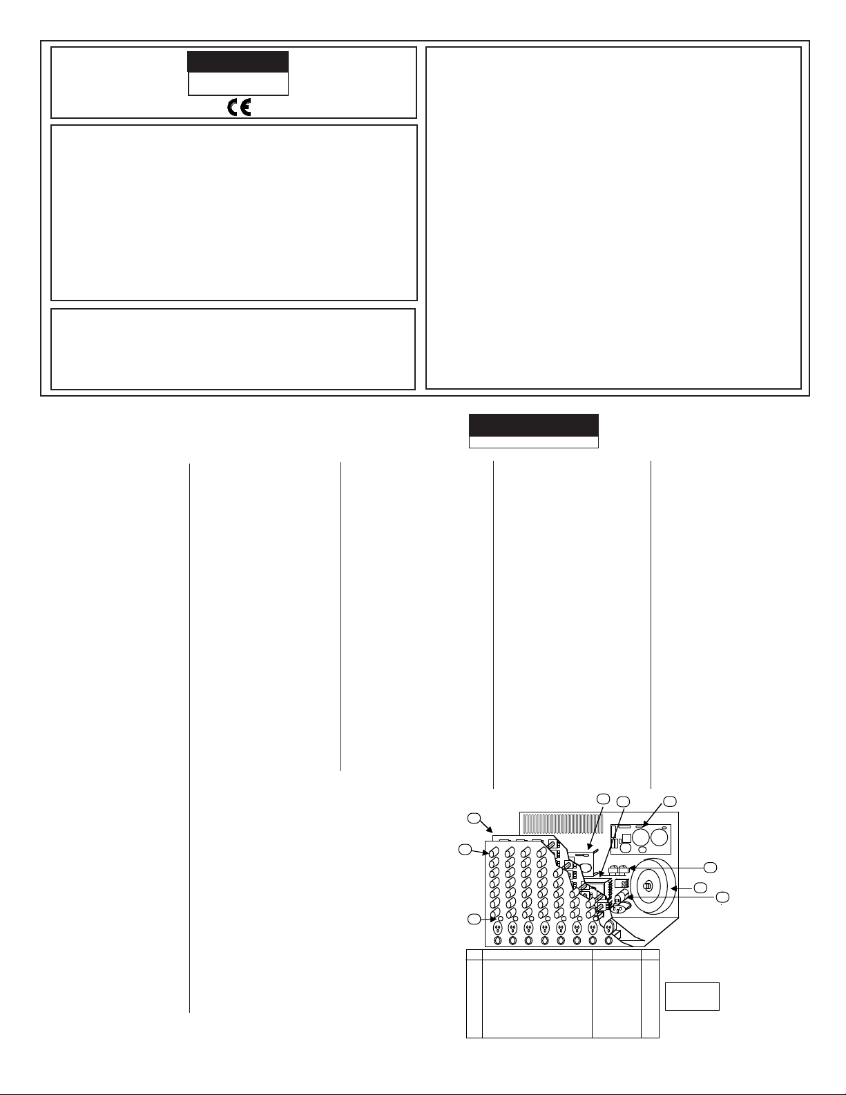
# DESCRIPTION CARVIN # QTY
1.
Switch Cap Grey Extended 07-01603 15
2.
Knob 11 D shaft (COLOR) 07-120-- ---
3.
Front Panel PCB (12 Chan) 30-12724 1
4.
Power Module 750Watts 80-07548 1
5.
Power supply PCB 80-07548 1
6.
DSP Reverb PCB --------- 1
7.
Speaker Output PCB
Circuit Breaker 70-28110
8.
toroid transformer 750Watts 15-75160 1
9.
30-12524-3
Color Knob Code
Red
Blue
Drk Grey
1
1
12
36
42
Page 2
CARVIN ENGINEERING DATA CX672 6CH, CX872 8CH & CX1272 12CH STEREO MIXER OPERATING MANU-
AL
THREE BAND
CHANNEL TONE
CONTROLS
PAD
-20dB
PAD SWITCH
HI MID LOW
MIC
PRE
CHANNEL
LEVEL
CHANNEL
EFF SND
CHANNEL
MONITOR
LEVEL
L
R
MON
EFF
EFFECTS
SUMMING AMP
EFFECTS
SEND 2
LEVEL
MAIN RIGHT
SUMMING AMP
AND LEVEL
MAIN LEFT
SUMMING AMP
AND LEVEL
EFFECTS
SEND 2
GAIN STAGE
NINE BAND
GRAPHIC
EQUILIZER
LEFT
LINE OUT
RIGHT
LINE OUT
NINE BAND
GRAPHIC
EQUILIZER
EFFECTS
SEND 2
INTERNAL
DSP SEND
GAIN
REDUCTION
FOR DSP
MONITOR
SUMMING AMP
MONITOR
LINE OUT
LEFT
AMP PATCH
RIGHT
AMP PATCH
DSP RETURN LEFT
DSP RETURN RIGHT
EFFECTS RETURN LEFT
EFFECTS RETURN RIGHT
EFF INPUT LEFT
TAPE RTN RIGHT
TAPE RTN LEFT
STEREO RETURN
FOR INTERNAL
STEREO DSP
RIGHT
TAPE OUT
LEFT
TAPE OUT
TO INTERNAL
POWER AMP
PAN
DSP TO
MONITOR
EFF INPUT RIGHT
CX 1
BLO
Part No.
CHANNEL
line pad
(-26dB)
12340 World Trade Drive, San Diego, CA 92128
(619) 487-1600 (800) 854-2235
www.carvin.com
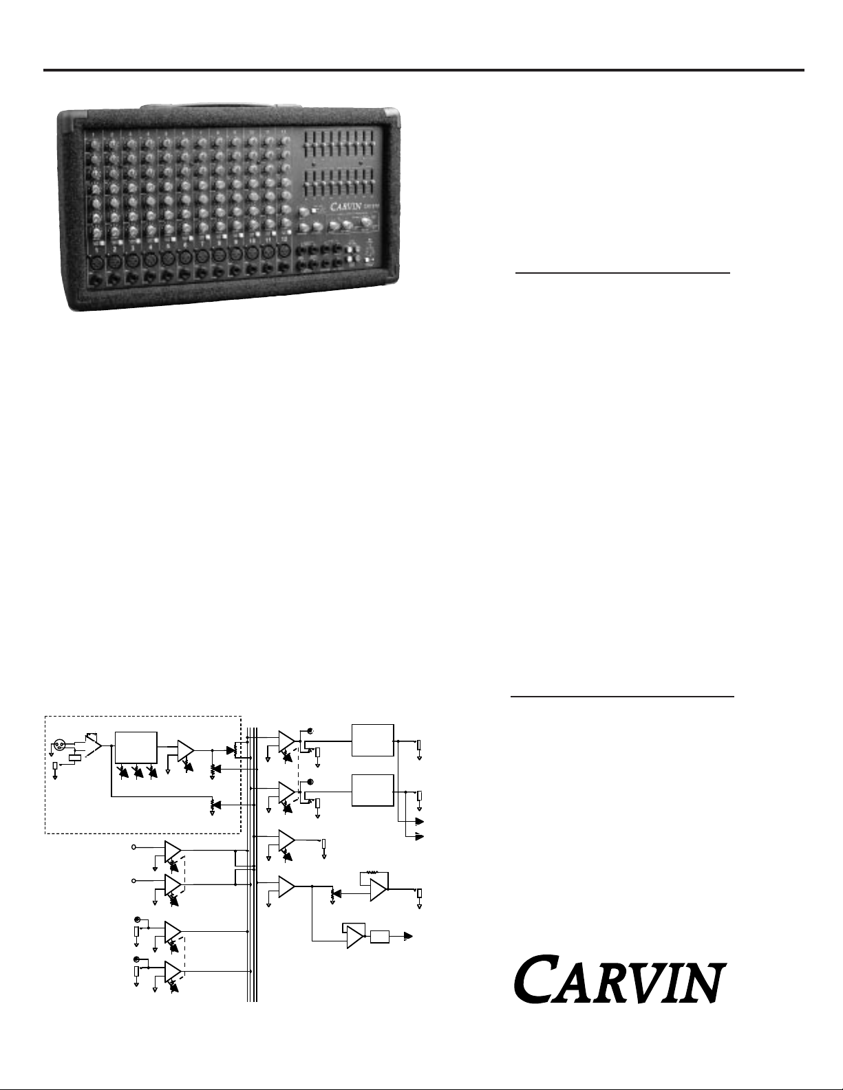
Congratulations on the purchase of your CX mixer. Your new CX series
mixer demonstrates CARVIN’s commitment to producing the highest
quality and most sophisticated engineering in the audio industry today.
The CX series mixers were designed to be professional mixers in compact units. The CX includes a full function stereo mixer, with two nine
band graphic equalizers, a digital signal effects processor and a powerful
stereo amplifier. A rack mount version is also available without power
amps. Each CX series mixer is surrounded by a strong, lightweight 3/4”
poplar plywood cabinet covered with Duratuff II™ carpeting making the
CX mixer road worthy.
CX OVERVIEW
The MIC/LINE input channels feature XLR and 1/4” LINE inputs with phantom power for
condenser mics. There are 3 bands of EQ, a post fader effect send, and a monitor prefader send on each channel. The master section features two 9 band graphic EQs, master
stereo main and monitor mix controls, a complete 16 program effects processor with send
and return controls, and a stereo external effects return.
“SHELVING” EQ WITH ACTIVE TONE CIRCUITS
The CX series incorporates 3 bands of EQ per channel. They offer smooth tone curves so
your adjustments will sound natural and yet be effective. The high (treble) and low (bass)
“shelving” type controls cover the complete upper and bottom portions of the audio range.
The MID EQ controls are a “band pass” type which peak at 2.2k Hz for added presence to
your mid range tones. Because CARVIN uses “active” tone circuits, you are able to boost
or cut your tones without any signal loss to your sound.
RECEIVING INSPECTION—read before getting started
INSPECT YOUR MIXER FOR ANY DAMAGE which may have occurred during shipping.
If any damage is found, please notify the shipping company and CARVIN immediately.
SAVE THE CARTON & ALL P ACKING MA TERIALS. In the event you have to re-ship your
unit, always use the original carton and packing material. This will provide the best possible protection during shipment. CARVIN and the shipping company are not liable for
any damage caused by improper packing.
SAVE YOUR INVOICE. It will be required for warranty service if needed in the future.
SHIPMENT SHORTAGE. If you find items missing, they may have been shipped separately. Please allow several days for the rest of your order to arrive before inquiring.
RECORD THE SERIAL NUMBER on the enclosed warranty card or below on this manual for your records. Keep your portion of the card and return the portion with your
name and comments to us.
INTERNAL SIGNAL ROUTING
Your balanced mic or instrument plugs directly into the high quality XLR Neurtric™
connectors and is then routed into the differential circuits for excellent hum and noise
cancellation. As your signal continues within the console, a double-sided printed circuit
board (FR-4 fire rated) carefully guards the circuit traces with a copper shield running
over the traces. This eliminates RF interference and reduces crosstalk substantially. The
printed circuit board has plated-through holes which means that every component is
soldered securely in three places (bottom, in the hole and on top). This offers unsurpassed component security while reducing circuit resistance for pure dynamic sound.
HEADROOM
Headroom is very important when designing a mixer—especially for recording. Lack of
headroom will cause your sound to become distorted and muddy. This can happen when you
turn the volume too high, if the input signal is too hot or if excess bass or treble is added.
With most mixers, you have to reduce the input gain to fight headroom problems, but this
just increases noise. That’s why we have taken great care in the CX series to make sure that
each gain stage is properly designed and balanced for more headroom along the entire audio
path.
TOROID SUPPLY
A big feature in the CX power supply is the precision wound Toroid transformer (not
available from our competitors) that offers lighter weight with massive current capability for the power amp. The toroid based power supply also offers unsurpassed rejection
of noise and hum while providing precision voltage for all preamp stages. Now you can
go anywhere and never worry about inconsistent sound due to fluctuating voltages.
CARVIN has spared no expense to achieve the best possible quality & performance.
For your records, you may wish to record the following information.
Serial No._____________________ Invoice Date_______________
CX672 / CX872 / CX1272 / CX1272R
76-01272 0798
CX672, CX872 & CX1272 SPECIFICATIONS:
Frequency Response: Mic or Line Inputs: 20Hz-20KHz ±2dB
Total Harmonic Distortion: Less than .1%
Equivalent Input Noise: 150 ohm source: -110dBu
Output Noise: -90dBu Master Line Out
(all levels minimum)
Output Power: (Power Mixers Only)
CX872 & CX1272 : 8Ω: 175/175 w, 4Ω: 250/250 w
2Ω: 375/375 w, less than 1% THD
Output Headroom: +20dB 1/4” unbalanced
Maximum Gain: Mic in to Master Line Out: 70dB
Crosstalk: Adjacent ch’s: -60db at 1KHz
Common Mode Rejection: -80db at 1KHz
Phantom Power: All XLR Mic in channels
Channel EQ.: 3 band active, LOW: 80Hz
±12dB
MID: 2.2KHz ±12dB
HI: 11.5KHz ±12dB
Graphic EQ.: 9 Band Oct. Intervals ±12dB
Mic Input: Balanced XLR input
Line Input: Unbalanced 1/4” Phone Jack
Power Consumption: 700VA
Size: 11”H x 19.5”W x9”D
Rack Model: 8.75”H x 19”W x 7.75”D
CX672, CX872, CX1272 BLOCK DIAGRAM
Page 3

QUICK START UP
If you’re like most new owners, you’re probably in a hurry to plug
your CX mixer in and use it. Here are some brief instructions to get
you going quickly. With the mixer unplugged and the unit turned off,
complete the following procedures:
1.CONNECTING AC POWER TO YOUR MIXER
• Check the rear panel to make sure the mixer has the correct AC
Line Voltage. (120VAC or 240 VAC)
• Use only a grounded (3 prong) power outlet to prevent a shock
hazard. This gives the quietest grounding for your mixer.
2.CONNECTING SPEAKERS (Powered Models Only)
• Use the 1/4” speaker jacks on the rear panel to connect up to four
8Ω speaker systems per jack (daisy chain). The speaker cables
are to be non-shielded with a minimum size of 16 gauge.
NOTE: Do not run your speakers through microphone wire, gui-
tar cables, or multi-conductor microphone junction boxes
or “snakes” as they are sometimes referred to. This wire is normally shielded and of a very light gauge causing a substantial loss of power.
3.SpeakerGuard™ and the “PROTECT” LED
• The protect LED comes on along with the output relays in three
diff erent protection modes: Shorted speaker outputs,
Speaker Impedance below minimum rating, and when the
amplifier exceeds maximum operating temperature.
• In event the LED comes on, turn off the amplifier and Identify and
correct any speaker cable or speaker jack shorts and make sure
the total speaker Impedance for each output is 2 ohms or
greater. Also make sure the fan is not blocked and
check that cool air can circu late around the
rear of the mixer.
4.CONNECTING INPUTS TO YOUR MIXER
• For low level balanced devices such as microphones, plug into the
balanced MIC inputs using a shielded microphone cable with XLR
ends.
• For high level unbalanced devices such as instruments &
Keyboards plug into the LINE input jacks using a shielded cable
with 1/4” phone ends. Set the GAIN switch so the level control is not over sensitive.
5.TURNING YOUR MIXER ON
• Adjust all channel and master level controls to their off positions
• Adjust all “EQ” tone controls— the channel’s Hi, Mid, and Bass
and the two master 9 Band Graphic EQ’s to their center position.
• Adjust all the Channel “PAN” controls to their center position.
• Set the power amp switch (located next to main volume) out for stereo
mode
• Turn the mixer on by the rear panel power switch and watch for
the power LED to come on. Your mixer is now ready to operate.
MIC CHANNEL FEATURES
1. LINE INPUT JACK
The Line input is a 1/4” phone jack designed for unbalanced line and
instrument level inputs. Examples of these inputs would be instruments such as a guitar, a keyboard, an unbalanced mic, or a pre-amp
output. The line input can be used at the same time the mic input is
being used.
2. XLR MICROPHONE INPUT
The XLR Mic input is designed for balanced low impedance (microphone) input signals. The differential balanced input amplifier
reduces the common noise picked up on the microphone cables.
The XLR connector is wired as per the industry standard, pin 1 is
ground, pin 2 is non-inverting (positive), and pin 3 is inverting (negative). Phantom power is available on every XLR input jack when the
phantom power switch in the master section is pressed. This feature
allows condenser microphones to be run directly from the mixer.
Note: When using phantom power, make sure the phantom power is
switched off before connecting or disconnecting microphones to the
mixer. It is recommended to allow 5 seconds for the phantom power
to discharge before making any microphone connections. Also, to
avoid hearing a pop, turn down the master volume when turning on
the phantom power.
3. +20DB GAIN SWITCH
The gain switch increases the input sensitivity on both the line and
mic input jacks by 20dB. After determining the input is too low for
mixing with the level control, turn down the level control, press in
the gain switch, and adjust the level again. If distortion is heard
regardless of the channel level control’s setting, disengage this
switch to eliminate over-driving of the input amplifier.
4. CHANNEL LEVEL CONTROL
The Level control adjusts the final volume of the channel before
going to the Pan control. Here is where the individual channel volumes are adjusted to make up the desired mix heard at the main
outputs. A general rule to prevent distortion with in the mixer is to
always keep the MAIN master level the same or higher than the
channel LEVEL.
5. MONITOR LEVEL CONTROL
The Mon level control adjusts the volume of the channel going to the
monitor mix. Here is where the individual channel monitor volumes
are adjusted to make up the desired mix heard at the monitor output. The monitor level control is pre-channel level and pre-channel
tone controls. This means it is unaffected by adjustments in channel
level and tone controls. The purpose for this is so the main mix
adjustments for tone and level can be made without disturbing the
monitor mix.
6. CHANNEL PAN CONTROL
The Pan control adjusts where the channel is heard in the stereo
field of the stereo main outputs. If it is turned to the extreme left,
then the channel will only be heard in the left main output and similarly only in the right main output if turned to the extreme right. In
the center position the channel is heard equally in both the left and
right main outputs. A good starting point for the pan is in the center position. Then if stereo placement is needed, a quarter turn to
the desired side from the center position gives a smooth placement
in the stereo field, or if desired a full turn to one side gives a hard
placement.
7. CHANNEL EFFECTS 1&2 LEVEL CONTROL
The EFF 1&2 control adjusts the volume of the channel going to the
internal effects Send 1 master control, and directly to the EFF SND
2 output. The effects control is post-channel level and automatically tracks the channel’s level & tone controls.
8-10. CHANNEL TONE CONTROLS
Each channel features active tone controls LO, MID, and HI. All
three function as boost (clockwise) & cut (counter-clockwise) controls where the center 0 position is neutral. The LO and HI controls
are shelving type tone controls with corner frequencies at 80Hz and
11.5k Hz respectively. The MID control is a band pass type centered
around 2.2kHz. It is suggested the channel tone controls start out
in their center 0 positions. A good setting for added dynamics is to
set the LO & HI at +3, and the MID at -3.
MASTER SECTION FEATURES
11. MAIN MASTER LEVEL CONTROL
The Main control is the master volume control for all channels receiving
the signals from the channel pan controls. The Main feeds the Graphic
EQ, the main line out jacks and the internal power amplifier(s). If the
power amp switch is out, then the Main control sends a stereo mix from
all channels to both power amps. If the power amp switch is pushed in,
then the Main controls sends a mono mix from all channels to the left
power amp only, and the master MONITOR level sends the channel MON
to the right power amp only.
12. POWER AMP INPUT SELECTOR
The Power Amp selector selects the inputs to the two graphic EQ’s and
the power amplifiers. The out position is the normal stereo power mixer
mode. The inputs to the two EQ’s are the main left and right signals.
In the push in position the main left/right signals are combined to produce one mono signal (still controlled by the MAIN control). This mono
signal becomes the input signal to the left EQ (top EQ) and the left
power amp. Also, in the in position the output of the monitor jack and
control knob becomes the input signal for the right EQ and right power
amp.
13. MONITOR MASTER LEVEL CONTROL
The Monitor master level control is the master volume for the monitor mix heard in the monitor output. This volume receives its signals from the channel monitor level controls. If the power amp
CX672, CX872 & CX1272 CONTROLS
1
2
3
6
5
4
7
8- 10
CX672, CX872 & CX1272
Page 4

switch is pushed in, then this knob controls the input to the right
power amp.
14. SEND 1 LEVEL CONTROL-INTERNAL DSP
The Send 1 control is the master input volume for the internal
effects. This volume receives its signals from the EFF 1&2 control
on the channels. The typical use of effects send is to adjust for
maximum input to the internal effects before clipping (see DSP clip
LED)
15. DSP RETURN 1 LEVEL CONTROL
The RETURN 1 is the master stereo level control for the internal
digital effects processor which is fed back into the L/R stereo mix.
A small amount of effects is also sent to the monitor mix.
16. RETURN 2 LEVEL CONTROL
The return 2 control is the stereo effects and tape return volume control. It receives its input from both the L/R tape rtn RCA jacks and the
L/R 1/4” effects return jacks. This volume controls the return level
being fed back into the master L/R stereo mix. A mono return into the
stereo mix can be achieved by simply feeding the mono signal into
both Left and right return jacks. The stereo return can also be used
as another input to the stereo mix for a keyboard or other stereo gear.
17. MONITOR OUT
The Monitor line out jack is the monitor mix from the monitor master level control. This is a line level output to drive an external
power amplifier.
18. LEFT/RIGHT OUT
The Left/Right line out jacks are post graphic EQ line output jacks for
the stereo mix. The same signals are also being fed to the internal
power amplifier. Note: If the insert jacks are being used for patching
or if the power amp switch is being used, then that new signal will
also be present on the corresponding Left/Right Line Out jack. The
stereo mix may still be accessed at the RCA Tape Send jacks if needed.
19. INSERT JACKS
The Left/Right INSERT jacks are pre-graphic EQ, pre-power amp,
and normalized to the stereo mix L/R MAIN level control. When a
mono plug is plugged into these jacks, the stereo mix is disconnected from the graphic EQ and internal power amplifier allowing
the new signal, that was plugged into the jack, to go through the
graphic EQ and to the internal power amplifier. In the insert mode
using a stereo (tip ring sleeve), the ring is the send and the tip is
the return. The typical use of these jacks is for the insertion of a
compressor or other outboard gear between the master preamp
and the power amp.
20. TAPE JACKS
The RCA jacks are Ideal for using a cassette deck. The Left/Right
Tape Send RCA jacks deliver the main mix output pre the graphic
EQ. If the Insert jacks are being used, the Tape Send jacks are a
way to access the main mix.
The Left/Right Tape Return are RCA inputs to the RETURN 2 &
TAPE level control. These tape return jacks can also be used for
returning another effects processor or instrument.
21. DSP EFFECTS SELECTOR
Select from 16 different effects that include: Flange, Reverb, EchoReverb, & Chorus-Reverb.
22. DSP INPUT CLIP LED
The DSP CLIP LED indicates the send level to the internal effects is
too high. To prevent clipping, adjust SEND 1 level control down until
the clipping LED stops flashing. The individual channel EFF 1 & 2 also
controls this level.
23. POWER LED
The Power LED indicates when the mixer is powered up.
24. PHANTOM POWER
SWITCH AND LED
The Phantom power switch turns on the microphone phantom
power in the channel XLR jacks. This power is used for supplying
a bias voltage to condenser microphones. The LED indicates the
phantom power is turned on. The phantom power will not damage
dynamic microphones.
25. CLIP INDICATOR
The red CLIP LED indicators will start to flash when the power amp
has reached its maximum output. Occasional flashing caused by
lower bass frequencies is OK. However, consistent flashing caused
from higher frequencies may damage high frequency drivers (exces-
sive distortion). This will not damage the amp.
26. THE GRAPHIC EQUALIZER
Each mixer has two nine band graphic EQ’s (equalizer). The graphic EQ’s are dedicated to the left and right outputs following (or
post) the insert jacks of the mixer. The 9 band Graphic EQ’s provide a wide degree of tonal flexibility.
Adjusting:
When the sliders are in their center detent position, they do not
affect the audio signal. When a slider is raised or lowered from the
center position, it boost and cuts respectively the level of a narrow
frequency band assigned to that particular slider. It is recommended that all sliders are set in their center position before equalizing your tone. Typically low frequency feedback is in the 125 and
250 Hz range while high feedback is in the 2k and 4k Hz range.
Occasionally one frequency (slider) of the equalizer will have to be
pulled down to stop feedback. If many of the sliders have to be
pulled down to stop feedback, the placement of the speakers with
respect to the microphones may need to be reconsidered. As
much as possible, try to have the main speaker facing away from
and in front of the microphones not on stage behind them. The
graphic EQ is mainly used to “equalize” the response of the main
room and reduce feedback from microphones. Don’t be afraid to
use the Graphic EQ, but take care not to over-adjust. Here are
some tonal reference ranges for the individual sliders to help relate
the frequencies in hertz to perceived tonal changes:
-the 63 Hz slider effects deep sub bass levels.
-the 125 Hz is typical bass adjustments.
-the 250, 500 and 1K Hz are for low mid and high mid adjustments.
-the 2K and 4K Hz are for lower treble adjustments.
-the 8K and 16K Hz are for the very high treble adjustments.
27. PROTECT LED INDICATOR
The red PROTECT LED provides the operator with information
about the status of the power amps. The PROTECT LED can come
on under 3 different conditions (when this happens both channels
are muted by disconnecting the output speaker relays);
1) During power-up, the amplifier stays in a muted state for
approx. 3 sec until it determines that everything is functioning normally (no output shorts or over temp conditions).
2) When the output load draws excessive current or a direct
short is detected caused by a shorted speaker cable or
speaker system. Reset this condition by turning the amp off
for two seconds and then on again. Check for shorted cables
and the total speaker system impedance connected to each
channel (2 ohms minimum per channel).
3) Overheating is usually determined when the amp stops in the
middle of a performance and the PROTECT LED is on. If this
is the cause, leave the amp on for the fan to cool the amp
down. The amp will automatically reset within 1 to 3 minutes.
The PROTECT LED will turn off when ready. Check for the
following conditions; a) The rear intake air is restricted from
outside air, b) Intake air is extremely warm, c) Excessive
speaker load (try other speakers or remove speakers if you
have more than one connected to each channel). Again, the
minimum impedance is 2 ohms per channel.
HELPFUL HINTS
1) FEEDBACK: To reduce feedback, the placement of the speakers with
respect to the microphones may need to be reconsidered. As much as
possible, try to have the main speaker facing away from and in front of
the microphones not on stage behind them. The graphic EQ may be
used to reduce feedback from microphones. See 26. THE GRAPHIC
EQUALIZER
2) SOUND HEARD ONLY ON LEFT SIDE: Check power amp selection
switch. Switch out for stereo mode, switch in for main/monitor mode.
3) No High Frequencies: Check the channel tone controls and EQ settings. The tweeters or midrange drivers may have been damaged or blown
from feedback or overpowering.
4) Main House AC breaker trips : at high output levels, high powered
amps require separate circuit breakers (120V:20A, 230V:10A) for delivering their full power. Most 120V homes have only 15 amp breakers you may
simply be running too much power
5) The Amp’s rear circuit breaker trips: Full power at 2Ω(4Ω bridged)
can cause the amps circuit breaker to trip. This is normal with high powered amps because they can deliver more than their full rated output if
the clip LED flashes.
17
13
11
12
16
14
15
26
23
27
19
18
20
24
25
21
22
Page 5

STEREO LIVE SOUND SYSTEM
In a live sound reinforcement or a public address system (P.A.
System), the input signals to the mixer will come from the microphones and instruments on the stage. Each microphone or instrument to be amplified by the P.A. system must be connected to one
of the mixing console inputs. It is preferred to have as many of the
stage instruments as possible plugged into the mixer. This allows
for the best overall sound control of the instruments as they are
mixed together and then amplified by the P.A. system. The mixer
can be operated on the stage or from a remote location in front of
the stage using a snake cable to bring the signals from the stage to
the mixer. The advantage of the remote operation allows the performance to be monitored and mixed from the audience’s perspective.
THE SOUND CHECK
The sound check takes some skill, but mostly patience from the
performers and especially you the system operator. If you get frustrated during the sound check the performers can lose confidence
and the sound may suffer due to things missed in the sound check.
The basic sound check follows this format: First test all microphones and other input devices(direct boxes, etc.) before the performers are included in the sound check. A good thing to also
check here is feedback in the monitors from the microphones.
Good positioning of the monitors and the use of the graphic equalizer solves most major monitor feedback problems. Now for a
sound check with the performers. First set the level of each performer individually and in cases where a performer has multiple
microphones, such as with a drummer, set each drum mic individually then the drum set as a whole. This is also a good time to
make some channel tone control adjustments to tailor the sound of
the individual performers and instruments. Next after setting each
individual, have the performers run through a song or a portion of
the show. Don’t hesitate to stop the performers if something needs
to be adjusted or if an individual performer or microphone needs to
be heard solo again. Remember the sound check is not a rehearsal, but a system check, a time to work the bugs out of the system
so the show can go smoothly. It is always a good idea for the mixer
operator to have a microphone to inform the performers of what is
needed during the sound check. If a monitor system is being used,
the mixer operator’s microphone should only be heard through the
monitors when addressing the on stage performers, especially if
something needs to be checked during the show. If the sound
check is allowed to run through its full course, the system should
run smoothly at show time.
MADE
AUS
INTHE
RIGHT LEFT
SPEAKERS
4Ω
MINIMUM IMPEDANCE
4Ω
250 250 WATTS
4Ω SPEAKER
4Ω SPEAKER
4Ω SPEAKER
4Ω SPEAKER
TWO-TRACK
TAPE RECORDER
AUX EFFECTS PROCESSOR
MONO IN
L OUT R
TAPE IN
TAPE OUT
CX1272
PHANTOM
TAPE
SEND
EFF SND 2MONITOR
POWER
PROTECT
RIGHT
INSERT
PRE EQ
POST EQ
LEFT RIGHT
TAPE
RETURN
POWER
RTN 2
CLIP
RIGHTLEFT
28
010
19
5
64
73
MAIN
RTN 2 &
TAPE
5
4
3
2
1
010
9
8
7
6
MONITOR
5
4
3
2
1
010
9
8
7
6
SEND 1
5
4
3
2
1
010
9
8
7
6
DIGITAL EFFECTS PROCESSOR
CLIP
CHORUS
REVERB
FLANGE
ECHO
RETURN 1
5
4
3
2
1
010
9
8
7
6
MONO &
MONITOR
POWER AMPS
SELECT
LINE OUT
REV
2
3
4
5
6
1
2
3
4
1
2
1
2
3
4
1
REV
REV
LEFT
/MONO /MONITOR
MAIN L / R
TAPE DECKS AND EXTERNAL EFFECTS
SPEAKER CONNECTION
DSP EFFECTS
Select from Reverb, Flange, Chorus, and Echo. Écho delays with reverb includes delay times of 50,100, 150, 250,
350, and 500 milliseconds.
The basic hook up is simple, using four (or
two stereo) RCA cables. Plug the TAPE
SEND on the mixer into the tape deck’s
inputs and the mixer’s TAPE RTN’s into the
tape deck’s outputs. With an external
effects processor, plug a 1/4” cable from
the EFF SEND output on the mixer into the
input jack on the effects processor. Then
from the outputs of the effects processor,
plug one or both (for stereo) cables into the
L/R EFFECTS RETURN.
MAIN
OR
STEREO LEFT
MONITOR
OR
STEREO RIGHT
4 SPEAKER SYSTEM
2Ω per channel
MADE
AUS
INTHE
RIGHT LEFT
SPEAKERS
4Ω
MINIMUM IMPEDANCE
4Ω
250 250 WATTS
8Ω SPEAKER
8 Ω SPEAKER
8Ω SPEAKER
8 Ω SPEAKER
8 Ω SPEAKER
8 Ω SPEAKER
8 Ω SPEAKER
8 Ω SPEAKER
8 SPEAKER SYSTEM
2Ω per channel
MAIN
OR
STEREO LEFT
MONITOR
OR
STEREO RIGHT
5
64
POWER AMPS
73
28
19
010
MAIN
5
4
6
3
7
2
8
1
9
010
MONITOR
5
4
3
2
1
010
RTN 2 &
TAPE
MAIN L / R
MONO &
MONITOR
6
7
8
9
4
3
2
1
010
SEND 1
DIGITAL EFFECTS PROCESSOR
5
6
7
8
9
CLIP
5
4
3
2
1
010
RETURN 1
6
7
8
9
REVERB
FLANGE
REV
CX1272
2
3
1
ECHO
4
4
5
3
2
1
SELECT
REV
6
1
2
2
3
1
4
CHORUS
REV
Page 6

125 250 50063 1K 2K 4K 8K 16K
8 9 10
MON
PAN
11
LEVEL
MON
PAN
LR
0
12
MIC
0
8
4
4
8
–12
+12
0
8
4
4
8
–12
+12
125 250 50063 1K 2K 4K 8K 16K
8 9 10 11 12
5
4
3
2
1
010
9
8
7
6
5
4
3
2
1
010
9
8
7
6
LEVEL
LR
0
MIC
5
4
3
2
1
010
9
8
7
6
5
4
3
2
1
010
9
8
7
6
MON
PAN
LEVEL
0
MIC
5
4
3
2
1
010
9
8
7
6
5
4
3
2
1
010
9
8
7
6
MON
PAN
LEVEL
0
MIC
5
4
3
2
1
010
9
8
7
6
5
4
3
2
1
010
9
8
7
6
MON
PAN
LEVEL
0
MIC
5
4
3
2
1
010
9
8
7
6
5
4
3
2
1
010
9
8
7
6
MON
PAN
LEVEL
0
MIC
5
4
3
2
1
010
9
8
7
6
5
4
3
2
1
010
9
8
7
6
MON
PAN
LEVEL
0
MIC
5
4
3
2
1
010
9
8
7
6
5
4
3
2
1
010
9
8
7
6
MON
PAN
LEVEL
0
MIC
5
4
3
2
1
010
9
8
7
6
5
4
3
2
1
010
9
8
7
6
MON
PAN
LEVEL
0
MIC
5
4
3
2
1
010
9
8
7
6
5
4
3
2
1
010
9
8
7
6
MON
PAN
LEVEL
0
MIC
5
4
3
2
1
010
9
8
7
6
5
4
3
2
1
010
9
8
7
6
MON
PAN
LEVEL
0
MIC
5
4
3
2
1
010
9
8
7
6
5
4
3
2
1
010
9
8
7
6
MON
PAN
LEVEL
0
MIC
5
4
3
2
1
010
9
8
7
6
5
4
3
2
1
010
9
8
7
6
MIDHIMID
LOW
HI
0
3
6
9
12
3
6
9
12
0
3
6
9
12
3
6
9
12
0
3
6
9
12
3
6
9
12
0
3
6
9
12
3
6
9
12
0
3
6
9
12
3
6
9
12
0
3
6
9
12
3
6
9
12
MID
LOW
HI
0
3
6
9
12
3
6
9
12
0
3
6
9
12
3
6
9
12
0
3
6
9
12
3
6
9
12
MID
LOW
HI
0
3
6
9
12
3
6
9
12
0
3
6
9
12
3
6
9
12
0
3
6
9
12
3
6
9
12
MID
LOW
HI
0
3
6
9
12
3
6
9
12
0
3
6
9
12
3
6
9
12
0
3
6
9
12
3
6
9
12
HI
0
3
6
9
12
3
6
9
12
0
3
6
9
12
3
6
9
12
0
3
6
9
12
3
6
9
12
MID
LOW
HI
0
3
6
9
12
3
6
9
12
0
3
6
9
12
3
6
9
12
0
3
6
9
12
3
6
9
12
MID
LOW
HI
0
3
6
9
12
3
6
9
12
0
3
6
9
12
3
6
9
12
0
3
6
9
12
3
6
9
12
MID
LOW
HI
0
3
6
9
12
3
6
9
12
0
3
6
9
12
3
6
9
12
0
3
6
9
12
3
6
9
12
HI
0
3
6
9
12
3
6
9
12
0
3
6
9
12
3
6
9
12
0
3
6
9
12
3
6
9
12
MID
LOW
HI
0
3
6
9
12
3
6
9
12
0
3
6
9
12
3
6
9
12
0
3
6
9
12
3
6
9
12
MID
LOW
HI
0
3
6
9
12
3
6
9
12
0
3
6
9
12
3
6
9
12
0
3
6
9
12
3
6
9
12
LRLRLRLRLRLRLRLRLRLR
7654321
7654321
EFF /
REV
5
4
3
2
1
010
9
8
7
6
EFF /
REV
5
4
3
2
1
010
9
8
7
654
3
2
1
010
9
8
7
6
EFF /
REV
5
4
3
2
1
010
9
8
7
6
EFF /
REV
5
4
3
2
1
010
9
8
7
6
EFF /
REV
5
4
3
2
1
010
9
8
7
6
EFF /
REV
5
4
3
2
1
010
9
8
7
6
EFF /
REV
5
4
3
2
1
010
9
8
7
654
3
2
1
010
9
8
7
6
EFF /
REV
5
4
3
2
1
010
9
8
7
6
EFF /
REV
5
4
3
2
1
010
9
8
7
6
EFF /
REV
5
4
3
2
1
010
9
8
7
6
EFF /
REV
EFF /
REV
-20
dB
MID MID
-20dB-20dB-20dB-20dB-20dB-20dB-20dB-20dB-20dB-20dB-20
dB
LINELINELINELINELINELINE LINELINELINELINELINELINE
R GRAPHIC EQ
L GRAPHIC EQ
MONITOR SPEAKERS
EXTERNAL
POWER AMP
TO REAR
SPEAKER OUTPUTS
CHANNEL
1
2
3
4
5
6
7
8
91011
12
13
15
17
19
22
30
50
0 dB
PROTECT CHANNELPOWER
1
2
3
4
5
6
7
8
91011
12
13
15
17
19
22
30
50
0 dB
12
RIGHT
PA CABINET
LEFT
PA CABINET
CX1272
PHANTOM
TAPE
SEND
EFF SND 2
MONITOR
POWER
PROTECT
RIGHT
INSERT
PRE EQ
POST EQ
LEFT RIGHT
TAPE
RETURN
POWER
RTN 2
CLIP
RIGHTLEFT
28
010
19
5
64
73
MAIN
RTN 2 &
TAPE
5
4
3
2
1
010
9
8
7
6
MONITOR
5
4
3
2
1
010
9
8
7
6
SEND 1
5
4
3
2
1
010
9
8
7
6
DIGITAL EFFECTS PROCESSOR
CLIP
CHORUS
REVERB
FLANGE
ECHO
RETURN 1
5
4
3
2
1
010
9
8
7
6
MONO &
MONITOR
POWER AMPS
SELECT
LINE OUT
REV
2
3
4
5
6
1
2
3
4
1
2
1
2
3
4
1
REV
REV
LEFT
/MONO /MONITOR
MAIN L / R
STEREO PA WITH EXTERNAL MONITOR SYSTEM
MONO PA WITH MONITORS
Power Amp selector IN
MAIN controls mono front speaker volume
MONITOR controls monitor speaker volume
POWER AMP
selector OUT
FROM LEFT
SPEAKER OUTPUT
+12
HI
HI
0
0
3
3
3
8
6
6
6
4
9
9
9
0
12
12
12
12
MID
MID
4
0
0
3
3
3
8
6
6
6
9
9
9
–12
12
12
12
12
LOW
LOW
0
0
3
3
3
6
6
6
9
9
9
12
12
12
12
EFF /
EFF /
+12
5
5
4
6
4
6
REV
REV
3
3
7
8
2
2
8
4
1
1
9
010
010
0
PAN
PAN
0
0
4
8
–12
5
5
MON
MON
4
6
4
6
3
3
7
2
2
8
1
1
9
010
010
5
5
4
6
4
6
3
3
7
2
2
8
1
1
9
010
010
LEVEL
LEVEL
dB
MIC
MIC
HI
HI
HI
3
6
9
MID MID
3
6
9
3
6
9
EFF /
REV
7
8
9
PAN
MON
7
8
9
7
8
9
0
0
0
3
3
3
6
9
12
3
6
9
12
3
6
9
12
4
3
2
1
010
4
3
2
1
010
4
3
2
1
010
LEVEL
3
3
3
6
6
6
6
6
9
9
9
9
9
12
12
12
12
12
MID
MID
0
0
0
3
3
3
3
3
6
6
6
6
6
9
9
9
9
9
12
12
12
12
12
LOW
LOW
0
0
0
3
3
3
3
3
6
6
6
6
6
9
9
9
9
9
12
12
12
12
12
EFF /
EFF /
5
5
4
654
6
6
REV
REV
3
7
3
7
7
2
8
2
8
8
1
9
1
9
9
010
010
PAN
PAN
0
0
0
5
5
5
MON
MON
4
6
4
6
6
3
7
3
7
7
2
8
2
8
8
1
9
1
9
9
010
010
5
5
5
4
6
4
6
6
3
7
3
7
7
2
8
2
8
8
1
9
1
9
9
010
010
LEVEL
LEVEL
MIC
MIC
MIC
125 250 50063 1K 2K 4K 8K 16K
125 250 50063 1K 2K 4K 8K 16K
5
5
64
64
POWER AMPS
POWER AMPS
73
73
MAIN L / R
MAIN L / R
MONO &
MONO &
MONITOR
MONITOR
5
5
5
5
5
5
6
4
6
6
4
6
4
6
4
6
CLIP
CLIP
3
7
7
3
7
3
7
7
3
7
2
8
8
2
8
2
8
8
2
8
1
9
9
1
9
1
9
9
1
9
010
010
010
010
RTN 2 &
RTN 2 &
SEND 1
SEND 1
TAPE
TAPE
INSERT
RTN 2
INSERT
RTN 2
PRE EQ
PRE EQ
LEFT RIGHT
RIGHT
LEFT RIGHT
RIGHT
POST EQ
POST EQ
LINE OUT
LINE OUT
MONITOR
EFF SND 2MONITOR
EFF SND 2
L GRAPHIC EQ
R GRAPHIC EQ
DIGITAL EFFECTS PROCESSOR
DIGITAL EFFECTS PROCESSOR
REVERB
REVERB
5
5
4
6
4
6
3
7
3
7
2
8
2
8
1
9
1
9
FLANGE
FLANGE
010
010
REV
REV
RETURN 1
RETURN 1
TAPE
TAPE
RETURN
RETURN
TAPE
TAPE
SEND
SEND
CX1272
CX1272
1
1
4
4
3
3
2
2
1
1
2
2
1
1
SELECT
SELECT
2
2
3
3
ECHO
ECHO
4
4
5
5
REV
REV
6
6
1
1
2
2
3
3
4
4
CHORUS
CHORUS
REV
REV
POWER
POWER
PROTECT
PROTECT
RIGHTLEFT
RIGHTLEFT
CLIP
CLIP
PHANTOM
PHANTOM
POWER
POWER
MONO (LEFT)
PA CABINET
FROM RIGHT
MONO (LEFT)
PA CABINET
8 9 10 11 12
7654321
HI
HI
0
0
3
3
3
6
6
6
9
9
9
12
12
12
MID
0
0
3
3
3
6
6
6
9
9
9
12
12
12
LOW
0
0
3
3
3
6
6
6
9
9
9
12
12
12
EFF /
EFF /
5
5
4
4
6
REV
REV
3
3
7
2
2
8
1
1
9
010
010
PAN
PAN
0
0
5
5
MON
MON
4
4
6
3
3
7
2
2
8
1
1
9
010
010
5
5
4
4
6
3
3
7
2
2
8
1
1
9
010
010
LEVEL
LEVEL
7654321
MIC
MIC
HI
0
3
3
6
6
9
9
12
12
MID
0
3
3
6
6
9
9
12
12
LOW
0
3
3
6
6
9
9
12
12
EFF /
5
4
6
REV
3
7
2
8
1
9
010
PAN
0
5
MON
4
6
3
7
2
8
1
9
010
5
4
6
3
7
2
8
1
9
010
LEVEL
8 9 10
MIC
HI
HI
0
3
3
3
6
6
9
9
12
12
12
MID
0
3
3
3
6
6
9
9
12
12
12
LOW
0
3
3
3
6
6
9
9
12
12
12
EFF /
5
4
6
6
REV
3
7
2
8
1
9
010
PAN
0
5
MON
4
6
6
3
7
2
8
1
9
010
5
4
6
6
3
7
2
8
1
9
010
LEVEL
MIC
HI
0
0
0
3
3
3
3
3
3
6
6
6
6
9
9
12
MID
3
6
6
9
9
12
LOW
3
6
6
9
9
12
EFF /
REV
3
7
2
8
1
9
010
PAN
LRLRLRLRLRLRLRLRLRLR
MON
4
3
7
2
8
1
9
010
4
3
7
2
8
1
9
010
LEVEL
MIC
0
0
0
5
5
6
9
12
3
6
9
12
3
6
9
12
6
7
8
9
6
7
8
9
6
7
8
9
9
12
MIDHIMID
0
3
6
9
12
0
3
6
9
12
EFF /
5
4
REV
3
2
1
010
PAN
0
LR
5
MON
4
3
2
1
010
5
4
3
2
1
010
LEVEL
11
MIC
6
6
9
9
9
12
12
12
0
3
3
3
6
6
6
9
9
9
12
12
12
LOW
0
3
3
3
6
6
6
9
9
9
12
12
12
EFF /
5
4
6
654
REV
3
7
7
2
8
8
1
9
9
010
PAN
0
LR
MON
5
4
6
6
3
7
7
2
8
8
1
9
9
28
28
010
19
19
5
010
010
4
6
6
3
7
MAIN
MAIN
7
2
8
8
4
4
1
9
9
3
3
010
-20
-20dB-20dB-20dB-20dB-20dB-20dB-20dB-20dB-20dB-20dB-20
2
2
LEVEL
dB
1
1
010
010
12
MONITOR
MONITOR
LEFT
LEFT
/MONO /MONITOR
/MONO /MONITOR
MIC
LINELINELINELINELINELINE LINELINELINELINELINELINE
SPEAKER OUTPUT
MONITOR SPEAKERS
(RIGHT) SPEAKER OUTPUT
 Loading...