

Page 1

CARVIN ENGINEERING DATA CM98ST Large Diaphragm Tube Condenser Mic
OPERATING MANUAL
Congratulations on your purchase of the CM98ST tube microphone. This
large diaphragm mic is a precision device that will provide accurate
recordings of vocals and instruments. Stunning results can be acheived
from it’s wide-band fequency response and 6 micron edge terminated gold
sputtered diaphragm giving your recording a very warm, natural sound.
A special high pass filter eliminates unwanted low frequency rumble while
a -10dB pad switch prevents the diaphragm from being over-driven. Enjoy
your new world of professional recording.
RECEIVING INSPECTION—read before getting started
INSPECT YOUR MIC FOR ANY DAMAGE which may have occurred during shipping. If any
damage is found, please notify the shipping company and CARVIN immediately.
SAVE THE CARTON & ALL PACKING MATERIALS. In the event you have to re-ship your
unit, always use the original carton and packing material. This will provide the best possible protection during shipment. CARVIN and the shipping company are not liable for any
damage caused by improper packing.
SAVE YOUR INVOICE. It will be required for warranty service if needed in the future.
RECORD THE SERIAL NUMBER on the enclosed warranty card or below on this manual for
your records. Keep your portion of the card and return the portion with your name and comments to us.
CM98ST SPECIFICATIONS:
Type:
Condenser Pressure Gradient
Microphone with 1 inch dual diaphragm
and vacuum tube pre-amplifier
Freq. Range:
20Hz-20k Hz
Dynamic Range: 133 dB
Imp: ≥300 Ohms
Recommended Load Imp:
≥5000 Ohms
Pad Switch: 10dB
Max SPL for 1% THD:
125dB @ 1000 Hz
Low Cut Switch:
-6dB @ 120Hz
Polar patter:
Omni, Cardioid, Bi-Directional
and intermediate stages
Power Supply:
48V (Included)
Cable: 30 ft. Gold 7-pin cable
Mic Dimensions: 7”L x 2.25”W
Case: Aluminum flight case
12340 World Trade Drive, San Diego, CA 92128
800.854.2235 www.carvin.com
1. Plug the phantom power supply into the proper AC voltage.
2. With the power off, connect the gold 7-pin XLR mic cable to the MIC IN
on the power supply.
3. With the Shockmount connected to a mic stand, thread your CM98ST
mic into the shockmount and connect the 7-pin XLR mic cable.
4. Next, you will need a second XLR cable (not included) to connect the
OUTPUT of the power supply to your input device (ie. mixer, multi-track
recorder etc...).
5. Once connected, you can turn the power supply ON (make sure all volume,
gain knobs, or faders on your mixer are turned OFF).
6. Bring the mixer’s channel fader up. Speak into the mic to test the level.
7. Turn the mixer’s gain up on this channel and stop just before the signal
peaks.
8. Check for transients that can cause the signal to peak by speaking or
singing at the loudest volume you will perform at and adjust the gain
up or down as necessary.
9. With the signal levels set, adjust the polar pattern and any EQ that might
be needed.
10. You are now ready to record with your CM98ST mic.
CHECK LIST OF P
ARTS
CM98ST microphone
48v phantom power supply
AC cable for power supply
7-pin XLR mic cable
Shockmount
Soft carry pouch for mic
Aluminum flight case
For your records, you may wish to record the following information.
Serial No._____________________ Invoice Date_______________
CM98ST
GETTING STARTED QUICKLY
If you are like most people, you probably want to get started right away.
Great! You can read the rest of the manual later to learn the finer points
of recording with a condenser mic. In order to get started, you will need
your new CM98ST mic and the gold 7-pin XLR Mic Cable, phantom power
supply and a 120 V AC grounded power outlet. You will also need a microphone stand to attach the Shockmount to hold your CM98ST mic. Other
equipment needed may include other cables to connect to a mixer or recording device.
Page 2
CM98ST CONSTRUCTION AND CARE
CM98ST Introduction:
The CM98ST is a studio quality, multi-purpose Large Diaphragm Tube
Condenser microphone. It features a Gold Sputtered, 6 micron element
and premium, low noise tube preamp electronics, all suspended in a handsome, rock solid, machined casing. The CM98ST also features a 10 dB
pad switch for easy handling of really hot signals and a low cut switch
for reducing rumble and wind noise. This versatile microphone was developed with the pro studio in mind; so it is equally adept at reproducing
stunning vocal performances as it is at capturing the subtlest nuances of
a fine acoustic guitar. And with a maximum SPL of 135dB (145 dB with
10dB pad switch engaged), the CM98ST is also an excellent instrument
and percussion microphone. The Carvin CM98ST is your affordable ticket
to awesome studio sound!
Construction and Shockmount:
The internally braced CM98ST capsule is precision mounted behind a
heavy mesh screen of perforated metal with large openings that offers
complete protection while maintaining total “acoustic transparency”.
Nestled below, is the low noise, class A circuitry surrounded by the solid,
machined outer shell. When used with the low cut switch on along with
the included Shockmount, low frequency vibration and handling noise are
virtually eliminated (-72 dB below 40Hz)!
Power Supply:
The CM98ST comes standard with a heavy duty phantom power supply,
ensuring you will never experience noise or distortion during loud
dynamic passages due to insufficient current. The power supply connects
to the CM98ST conveniently via the included 7-pin gold XLR mic cable.
It also features 9 different selectable polar patterns including omni, cardioid and figure-8.
*Note: Carvin is not responsible for damage to your CM98ST caused by
an alternate power supply.
Flight Case:
The CM98ST, shockmount, power supply and cables, all fit snugly and
safely in a high grade, aluminum alloy flight case so you know your microphone and accessories are well protected between sessions or during travel.
Carvin recommends returning your CM98ST to this case after each use.
Care:
Tube condenser microphones do not like to be dropped, tapped, blown
into, shaken or stirred. The gold sputtered element is very thin and fragile and can easily be stretched or knocked out of alignment. This is true
of all large diaphragm condensers. Be very careful with your CM98ST!
If you drop it from any distance, the resulting damage will not be covered under your warranty.
Additionally, these mics don’t like moisture. It is always advisable to
use a pop screen (Carvin part #WS87)when micing vocals to avoid not
only overly accentuated “P”, “B”, and “S” sounds, but also to keep unwanted
moisture off of the element. Over time, moisture on the element can attract
airborne dust and dirt particles and gradually degrade the performance
of your mic. Carvin advises that the microphone be kept in its flight case
at all times when not in use. Take a few minutes after every session and
put your mic away properly to help ensure years of top notch performance.
Additionally, always make sure the silicone “moisture absorber” (little white
packet with crystals in it) is packed in the case with your microphone.
This will help to eliminate any moisture or humidity in the case during
storage. You can re-activate a saturated “moisture absorber” by baking
it in an oven at 250 degrees for about 30 minutes. The outer shell of your
mic can be cleaned with a soft damp cloth. Do not use harsh detergents,
solvents, or abrasive materials.
-10db
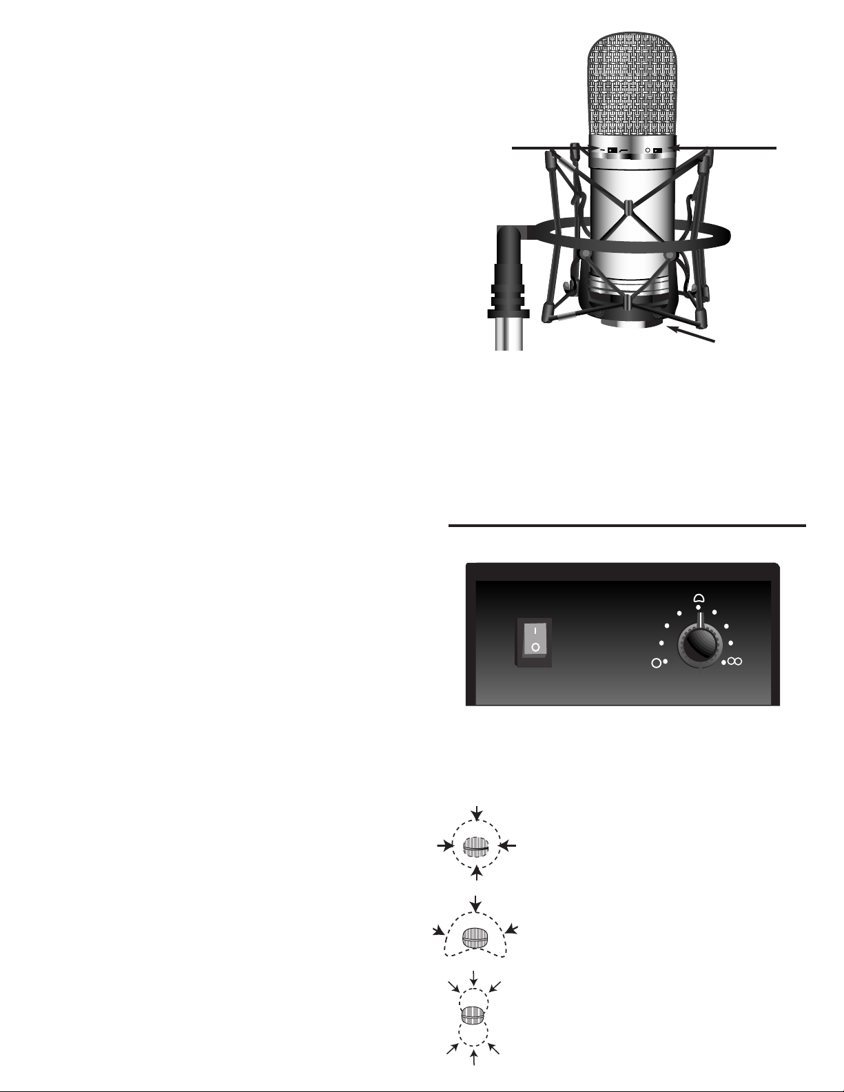
a) Shockmount
The shockmount will fit any standard mic stand. It is designed to hold the
CM98ST mic while reducing low frequency vibration. Place the CM98ST mic
into the shockmount cradle and thread the mic clockwise until it is snug. You
may also invert the shockmount so the mic is suspended.
b) Low cut switch
The Low Cut switch helps eliminate boomy low end frequencies (
-6dB @ 80Hz)
c) 10dB pad switch
This switch changes the mic’s maximum Sound Pressure Level (SPL) of 135 dB
to 145 dB. Switch to an SPL of 145 dB when recording loud sources.
c) 10 dB pad
b) Low Cut
a) Shockmount
ON
POWER
TUBE MIC POWER SUPPLY
DIRECTIONAL PATTERN
top view of mic
top view of mic
top view of mic
An Omni-directional pattern will give your mic the ability to pickup sound from all directions. This is ideal for
recording sounds that emanate from multiple directions.
The Cardioid pattern is ideal for single instrument or vocal
use. The pattern picks up only sound directly in front of
the mic. Sound from the other direction is rejected.
Bi-directional or Figure 8 will hear sound from both front
and back. This is ideal for recording a main sound while
still picking up room ambience from behind or duets with
two vocalists.
DIRECTIONAL POLAR PATTERNS
The CM98ST power supply includes a switch to change the mic’s directional polar pattern. The three primary patterns are Omni, Cardioid and
Bi-Directional or also known as Figure 8. The stages inbetween will grad-
ually change the directional pattern and can provide some very useful and
subtle tone and response variations to suite your recording needs.
Page 3

STUDIO SET UP
Compressor
The illustration below shows the standard set up in a recording studio.
The shockmount should be set on a round or tripod base mic stand. The
CM98ST should always set in the shockmount to eliminate any noise or
vibrations from the floor or walls. The phantom power supply should be
connected to a 120 V AC outlet. Be sure the power supply is properly
grounded and never defeat the ground on the AC plug. The gold 7-pin
XLR mic cable should be connected to the MIC IN on the power supply
and then connected to the CM98ST mic. High quality XLR cables should
always be used for mixer connections such as Carvin’s XLR25. The OUTPUT
jack on the power supply will pass the mic’s signal to the MIC input on a
mixer. Always disable any phantom power that may be present on the
mixer as you will be using an external source for phantom power.
Many professionals use a compressor/limiter when recording. They are
ideal for eliminating transient signals. Transients are those quick changes
in volume that can cause a performance to sound too loud in some areas.
A compressor/limiter will keep the signal at a constant volume while limiting any peak signals. The result is a “hot” and constant signal that is
ideal for both vocal performances and recording. The illustration below
shows a typical set-up for inserting a compressor/limiter.
With today’s high quality digital audio hardware, recording at home has
never been so easy and affordable! When recording to a digital or analog
format of any kind, be sure to achieve the strongest signal into your mixer
without clipping or distorting. This will give you the best signal to noise
ratio for professional sounding recordings.
XLR Cable
CHANNEL 1
RATIO
THRESHOLD
ATTACK
RELEASE
50
0
BYPASS
100
20
120
10
230
10
TH 36
10
200
91215
-30 +6
Insert Out
Gold 7-pin XLR Cable
OUTPUT
100
5
200
10
0
INPUT
OUTPUT
CLIP
CLIP
GATE
20
10
Insert In
50
120
230
GATE
CHANNEL 2
THRESHOLD
0
BYPASS
-30 +6
TH 36
-10db
RATIO
OUTPUT
ATTACK
RELEASE
50
100
100
20
10
91215
5
120
230
10
20
10
200
200
10
0
INPUT
OUTPUT
CLIP
CLIP
XLR
Mic
ON
GATE
50
120
10
230
GATE PWR
CGL200
OFF
TRS
Insert
Input
21
LINE
LINE
MIC
MIC
DIR - INSERT
DIR - INSERT
050
050
GAIN
GAIN
HI
HI
MID
LOW
3-5
4-6
+
+
0
-
-24
-30
-50
-15
-15
-15 +15
1
010
2
010
010
010
LR
12
6
12
0
LO
CUT
+15
0
MID
SHIFT
+15
0
AUX
5
5
PRE
POST
5
5
5-6
PAN
C
SIG
PEAK
MUTE
PFL
1-2
3-4
L-R
MID
LOW
3-5
4-6
+
+
0
-
-24
-30
-50
-15
-15
-15 +15
1
2
12
6
12
0
+15
0
+15
0
5
010
5
010
5
010
5
010
C
LR
PEAK
HI
LO
CUT
MID
MID
SHIFT
LOW
1
AUX
2
PRE
POST
3-5
4-6
5-6
PAN
SIG
+
MUTE
+
PFL
0
1-2
-
3-4
-
-
L-R
-
Page 4

CAUTION
RISK OF ELECTRIC SHOCK
DO NOT OPEN
SAFETY INSTRUCTIONS (EUROPEAN)
The conductors in the AC power cord are colored in accordance with the following code.
GREEN & YELLOW—Earth BLUE—Neutral BROWN—Live
U.K. MAIN PLUG WARNING: Amolded main plug that has been cut off from the cord is
unsafe. NEVER UNDER ANYCIRCUMST ANCES SHOULD YOU INSER TADAMAGED
OR CUT MAIN PLUG INTO APOWER SOCKET.
IMPORTANT! FOR YOUR PROTECTION, PLEASE READ THE FOLLOWING:
WATER AND MOISTURE: Appliance should not be used near water (near a bathtub, washbowl,
kitchen sink, laundry tub, in a wet basement, or near a swimming pool, etc). Care should be taken
so that objects do not fall and liquids are not spilled into the enclosure through openings.
POWER SOURCES: The appliance should be connected to a power supply only of the type described
in the operating instructions or as marked on the appliance.
GROUNDING OR POLARIZATION: Precautions should be taken so that the grounding or polarization means of an appliance is not defeated.
POWER CORD PROTECTION: Power supply cords should be routed so that they are not likely
to be walked on or pinched by items placed upon or against them, paying particular attention
to cords at plugs, convenience receptacles, and the point where they exit from the appliance.
SERVICING: The user should not attempt to service the appliance beyond that described in the
operating instructions. All other servicing should be referred to qualified service personnel.
FUSING: If your unit is equipped with a fuse receptacle, replace only with the same type fuse.
Refer to replacement text on the unit for correct fuse type.
This symbol is intended to
alert the user to the presence of uninsulated “dan-
gerous voltage” within the
product’s enclosure that may be of sufficient magnitude to constitute a risk of
electric shock to persons.
This symbol is
intended to alert the
user to the presence of
important operating
and maintenance (servicing) instructions in the literature accompanying
the appliance.
LIMITED WARRANTY
Your Carvin product is guaranteed against failure for ONE YEAR unless otherwise stated. Carvin will
service and supply all parts at no charge to the customer providing the unit is under warranty. Shipping
costs are the responsibility of the customer. CARVIN DOES NOT PAY FOR PARTS OR SERVICING OTHER
THAN OUR OWN. A COPY OF THE ORIGINAL INVOICE IS REQUIRED TO VERIFY YOUR WARRANTY.
This warranty does not cover, and no liability is assumed, for damage due to: dropping, moisture damage,
accidents, abuse, natural disasters, loss of parts, lack of reasonable care, incorrect use, or failure to
follow instructions. This warranty is in lieu of all other warranties, expressed or implied. No representative or person is authorized to represent or assume for Carvin any liability in connection with the
sale or servicing of Carvin products. CARVIN SHALL NOT BE LIABLE FOR INCIDENTAL OR CONSEQUENTIAL DAMAGES.
When RETURNING merchandise to the factory, you may call for a return authorization number. Describe
the problem in writing.
RECORDING TIPS
Lead Vocals
For micing vocals, the element should be close to the height
of the singer’s mouth in a normal comfortable singing position.
Some vocalists prefer the microphone slightly elevated. While
proper mic positioning is important for good sound, a relaxed,
comfortable singer is more important, so position the mic to the
singer’s liking (within reason!). Typically 6 to 12 inches away
from the mic is ideal for lead vocals, but feel free to experiment.
Every mic has a “sweet spot” where the voice reproduction sounds
best. That spot is unique for each voice! Experiment with distances to arrive at the “sweet spot”. When getting in close to
the mic, remember to use a pop screen to prevent “popping” your
“P’s” and excessive moisture from getting into the mic element.
Background Vocals
If you want the feeling of distance or space, take a step back
from the mic. Just be aware that as you get further away, you
may need more gain to achieve the desired recording levels. And,
with more gain comes the possibility of picking up unwanted
noise. When recording multiple vocalists on one mic, test each
person’s levels individually before recording them together. If
one vocalist is louder than the other, have that person take one
step back. Repeat this process until all vocalists can be recorded
at even levels with a single mic.
Recording Instruments
For instrument or percussion micing, there really is no right
or wrong placement except when you are recording multiple
instruments where proper “close micing” techniques must be
used to prevent excessive “bleed-through” between instrument
tracks. Never be afraid to try various positions or angles. Feel
free to change the acoustic properties of the recording environment by using sound absorbent panels and materials.
Additionally, try using multiple CM98ST’s at different placements
and distances. Example: When micing an electric guitar cabinet, try using one CM98ST’s up close (within several inches of
the speaker) and another at a further distance as an “ambience”
mic. You will achieve a totally different sound than with one mic
alone. Micing an acoustic guitar can be a whole art in itself. Start
out by placing the mic near the sound hole. Try moving the mic
closer to the bridge of the guitar for a brighter sound and closer
to the neck and sound hole to add low end frequencies. Using
a second mic at a distance can add ambience. The different sound
possibilities are limited only by your creativity and imagination!
LEAD VOCALS
BACKGROUND VOCALS
ACOUSTIC GUITAR
6 to 12 "
-10db
24 to 48 "
-10db
-10db
 Loading...