

Carrier T-55, T-56 Installation Instructions Manual

INSTALLATION INSTRUCTIONS
T-55 SPACE TEMPERATURE SENSOR WITH OVERRIDE
T-56 SPACE TEMPERATURE SENSOR WITH OVERRIDE & SETPOINT ADJUSTMENT
COMPONENT LIST
The Model T-55 Space Temperature Sensor with Override and T-56 Space Temperature Sensor
with Override & Setpoint Adjustment consists of the following components:
• (1) Space temperature sensor
• (2) 6-32" x 1" round head machine screws
LOCATING THE SENSOR
The T-55 and T-56 space temperature sensors measure building interior temperature and should be
located on an interior building wall. The sensor wall plate accommodates the NEMA standard 2 x 4
junction box. The sensor can be mounted directly on the wall surface if acceptable by local codes.
Do not mount the sensor in drafty locations such as near air conditioning or heating ducts, over heat
sources such as baseboard heaters, radiators, or directly above wall mounted lighting dimmers. Do
not mount the sensor near a window that may be opened, or near a wall corner or door. Sensors
mounted in these areas will have inaccurate and erratic sensor readings.
Mount the sensor approximately 5 ft from the floor, in an area representing the average temperature
in the space. Allow at least 4 ft between the sensor and any corner and mount the sensor at least 2 ft
from an open doorway.
Note: Clean sensor with damp cloth only. Do not use solvents.
TO INSTALL THE T-55 AND T-56 SENSOR
(See Figure 1 below)
1. Locate the two Allen-type screws at the bottom of the sensor.
2. Turn the two screws clockwise to release the cover from the sensor wall mounting plate.
3. Lift the cover from the bottom and then release it from the top fasteners.
4. Feed the wires from the electrical box through the opening in the center of the sensor mounting plate.
808-255
02/00
1
5. Using two no. 6-32 x 1 mounting screws (provided with the sensor) secure the sensor to the
electrical box.
6. Use 20 gage wire to connect the sensor to the controller. The wire is suitable for distances of
up to 500 ft. Use a three-conductor shielded cable for the sensor and setpoint adjustment
connections. The standard CCN communication cable can be used. If the setpoint adjustment
(slidebar) is not required, then an unshielded, 19 or 20 gage, two-conductor, twisted pair
cable can be used.
The CCN network service jack requires a separate, shielded CCN communication cable.
Always use separate cables for CCN communication and sensor wiring. (Refer to Figure 2 or
3 for wire terminations.)
7. Replace the cover by inserting the cover at the top of the mounting plate first, then swing the
cover down over the lower portion. Rotate the two Allen head screws counterclockwise until
the cover is secured to the mounting plate and located in position.
8. For more sensor information, see Table 2 for thermistor resistance vs. temperature values.
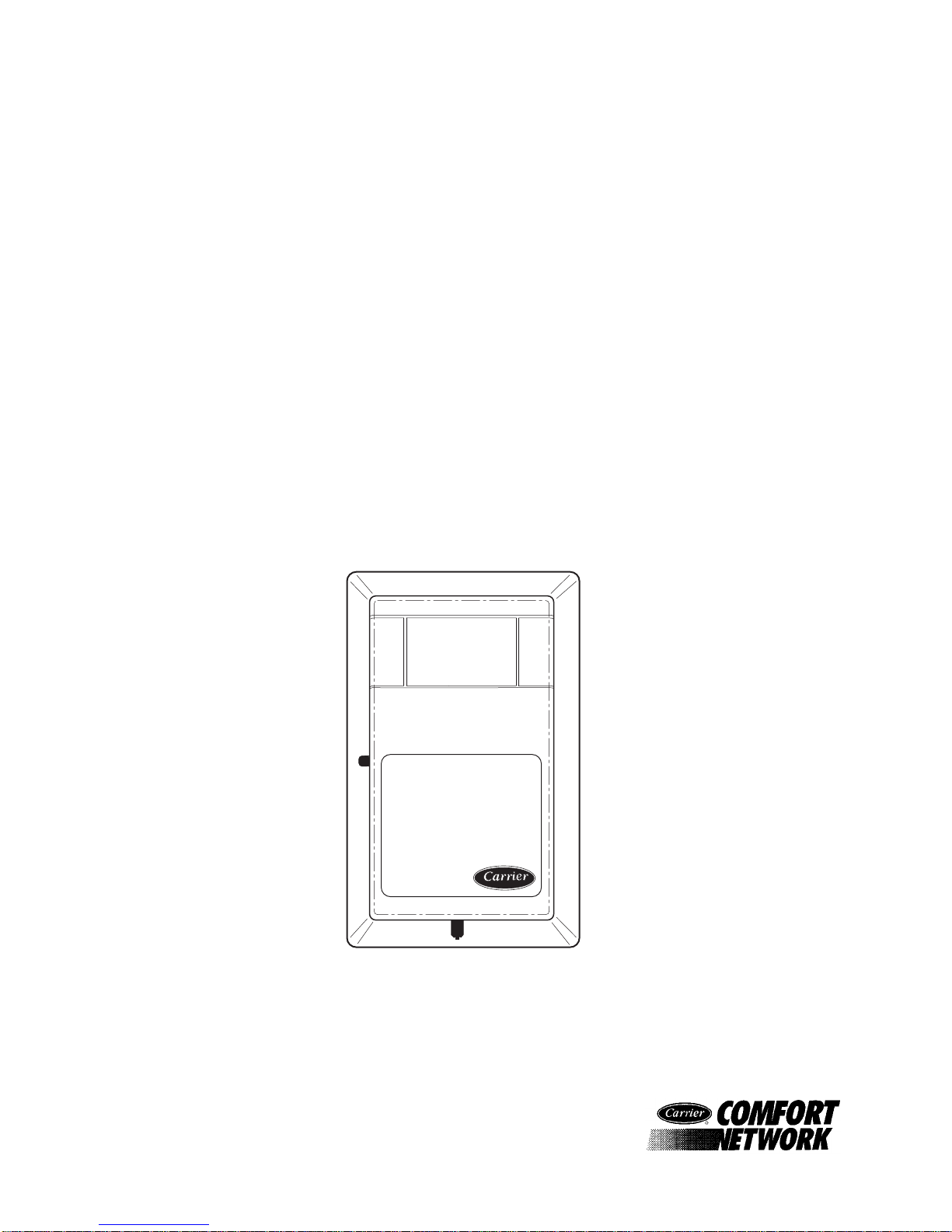
Figure 1
T-56 Space Temperature Sensor
808-255
02/00
Cool
Warm
2
 Loading...