

Carrier Stellar Inverter series Installation Manual

There s hould n ot be any h eat sou rce or st ream
near th e unit.
There s hould n ot be any o bstac les blo cking t he
air cir culat ion.
A place whe re air ci rcula tion in t he room i s good.
A palce whe re drai nage ca n be easi ly done .
A palce whe re nois e preve ntion i s taken i nto
consi derat ion.
Do not in stall t he unit n ear the d oor way.
Ensur e the spa ces ind icate d by arro ws from t he
wall, ceili ng,fe nce or ot her obs tacle s.
There s hould n ot be any d irect s unlig ht. If un avoid able,
sunli ght pre venti on shou ld be tak en into c onsid erati on.
1. Fit th e insta llati on plat e horiz ontal ly
on stru ctura l parts o f the wal l with
space s aroun d the ins talla tion pl ate.
2. If the w all is ma de of bri ck, con crete
or the li ke, dri ll eigh t (8) 5mm d iamet er
holes i n the wal l.Ins ert Cli p ancho r for
appro priat e mount ing scr ews.
3. Fit th e insta llati on plat e on the wa ll
with ei ght (8) t ype A screws.
Fit the I nstal latio n Plate a nd dril l
holes i n the wal l accor ding to t he
wall st ructu re and co rresp ondin g
mount ing poi nts on th e insta llati on
plate . The inst allation pla te
provi ded wit h the mac hine di ffer
from ap plian ce to app lianc e.
(Dime nsion s are in mm u nless
other wise st ated)
Corre ct orie ntati on
of Inst allat ion Pla te
1. Dete rmine h ole pos ition s accor ding to l eft and r ight
side of t he inst allat ion pla te. The ho le center is obt ained
by meas uring t he dist ance as s hown in t he diag ram abo ve.
2. Dirl l the pip ing pla te hole w ith φ65m m hole- core dr ill.
3. Dril l the pip ing hol e at eith er the ri ght or th e left an d the
hole sh ould be s light ly slan ted to th e outdo or side .
4. Always u se wall h ole con duit wh en dril ling me tal gri d,
metal p late or t he like .
1. For th e left- hand an d right -hand p iping ,
remov e the pip e cover f rom the s ide pan el.
2. For th e rear- right -hand a nd rear -left -hand
pipin g, inst all the p iping a s shown .
3. Bund le the tu bing, c onnec ting ca ble, an d
drain h ose wit h tape se curel y, evenly as
shown i n Figur e on the ri ght.
Becau se the co ndens ed wate r from re ar
of the in door un it is gat hered i n pondi ng
box and i s piped o ut of roo m. Do not p ut
anyth ing els e in the bo x.
1. Run th e drain h ose slo ping do wnwar d.
Do not in stall t he drai n hose as i llust rated
in Figu res.
2. When c onnec ting ex tensi on drai n hose,
insul ate the c onnec ting pa rt of ext ensio n
drain h ose wit h a shiel d pipe, d o not let
the dra in hose s lack.
Conne ct the in door un it firs t, then t he
outdo or unit .
Do not al low the p iping t o let out f rom the
back of t he indo or unit .
Be care ful not t o let the d rain ho se slac k.
Heat in sulat ed both o f the aux iliar y pipin g.
Be sure t hat the d rain ho se is loc ated at
the low est sid e of the bu ndle. L ocati ng at
the upp er side c an caus e drain p an to
overf low ins ide the u nit.
Never i nterc ross no r inter twist t he powe r
wire wi th any ot her wir ing.
Run the d rain ho se slop ped dow nward t o
drain o ut the co ndens ed wate r smoot hly.
Ancho r the out door un it with a b olt and n ut φ10 or
φ8 tight ly and ho rizon tally o n a concr ete or ri gid mou nt.
O
ut
d
oo r
u
ni
t
d
im e
n
s
i
o
n
m
m
(L 1
x
H
x
W1 )
L2 (mm ) W2 (mm )
53 0
29 0
56 0
54 9
48 1
33 5
27 6
27 6
Mo unt in g dime nsi ons
76 0x5 90 x285
84 5x7 00 x320
78 0x5 40 x250
67 0x5 40 x265
1. Pass t he pipi ng thro ugh the h ole in th e wall.
2. Hook t he indo or unit o nto the u pper po rtion
of inst allat ion pla te(En gage th e indoo r unit wi th
the upp er edge o f the ins talla tion pl ate). E nsure
the hoo ks are pr operl y seate d on the in stall ation
plate b y movin g it in lef t and lef t.
3. Pipi ng can ea sily be m ade by li fting t he indo or
unit wi th a cush ionin g mater ial bet ween th e
indoo r unit an d the wal l. Get it o ut afte r finis h
pipin g.
4. Pres s the low er left a nd righ t side of t he unit
again st the in stall ation p late un til hoo ks
engag es with t he thei r slots .
INSTALLATION MANUAL FOR ROOM
AIR CONDITIONER
(Split Wall-Mounted Type)
SELECT THE BEST LOCATION
In do or unit
DRILL A HOLE IN THE WA LL
Ou td oo r uni t
Se tt le me nt of out do or uni t
FIT THE INSTALLATION PLATE
2
CONNECTIVE PIPE AND D RAINAGE IN STALLATION
3
NOT E:
NOT E:
Fi t the Ins ta ll at io n Pla te
Co nn ec ti ve pipe inst al la ti on
Dr ai na ge
CAU TI ON
In do or unit ins ta ll at io n
1
The mou nting w all is st rong an d solid
enoug h to prev ent it fr om the vi brati on.
" "
"
"
If an awn ing is bu ilt ove r the uni t to prev ent
direc t sunsi ght or ra in,be c arefu l that he at
radia tion fr om the co ndens er is not o bstru cted.
There s hould n ot be any a nimal o r plant w hich
could b e affect ed by hot air disc harged.
Keep th e space s indic ated by a rrow fr om wall
ceili ng, fen ce or oth er obst acles .
Do not pl ace any o bstac les whi ch may ca use
a short c ircui t of the di schar ged air.
I
N
D
O
O
R
U
N
I
T
150mm or more to ceiling
Indoor unit outline
Installation plate
292
Right rear side
refrigerant
pipe hole φ65
Left rear side
refrigerant
pipe hole φ65
120mm or
more to wall
120mm or
more to wall
920
45
185
150
45
A
45
B
Right rear side
refrigerant
pipe hole φ65
Installation plate
Indoor unit outline
Left rear side
refrigerant
pipe hole φ65
150mm or more to ceiling
120mm or
more to wall
120mm or
more to wall
Mod el A (A: 7 10, B: 25 0, C:10 0, D: 160 )
Mod el B( )A: 79 0, B:26 5, C:10 0, D: 150
Mod el C
Mod el D
45
C
D
The seriousn ess is classi fied by the following indi cations.
This symb ol indica tes the possi bilit y of death or serious inj ury.
This symb ol indica tes the possi bilit y of injury or damage to prop erty.
1) This equipment must be earthed and installed with earth leakage current breaker. It may cause
electrical shock if grounding is not perfect.
2) Do not install the unit at place where leakage of flammable gas may occur. In case gas leaks and
accumulates at surrounding of the unit, it may cause fire.
3) Carry out drainage piping as mentioned in installation instructions. If drainage is not perfect, water
may enter the room and damage the furniture.
1) Install according to this installation instructions strictly. If installation is defective, it will cause water
leakage, electrical shock fire.
2) Use the attached accessories parts and specified parts for installation, otherwise, it will cause the set
to fall, water leakage, electrical shock fire.
3) Install at a strong and firm location which is able to withstand the set s weight. If the strength is not
enough or installation is not properly done, theset will drop and cause injury.
4) For electrical work, follow the local national wiring standard, regulation and this installation instructions.
An independent circuit and single outlet must beuse d. If electrical circuit capacity is noteno ugh or
defect found in electrical work, it willcau se electrical shock fire.
5) Use the specified cable and connect tightly and clamp the cable so that no external force will be acted
on the terminal. If connection orf ixing is not perfect, itwi ll cause heat-up or firea t the connection.
6) Wiring routing must be properly arranged so that control board cover is fixed properly. If control board
cover is not fixed perfectly,it will cause heat-up at connection point of terminal, fire orelec trical shock.
7) When carrying out piping connection, take care not to let air substances other than the specified
refrigerant go into refrigeration cycle. Otherwise, it will cause lower capacity,abnor mal high pressure
in the refrigeration cycle, explosion and injury.
8) Do not modify the length of the power supply cord or use of extension cord, and do not share the
single outlet with other electrical appliances. Otherwise, it will cause fire or electrical shock.
SAFETY PRECAUTIONS
CAUT ION
WAR NING
CAU TI ON
WA RN IN G
Please read this installation manual completely before installing the product.
If the power cord is damaged, replacement work shall be performed by authorised personnel only.
Installation work must be performed in accordance with the national wiring Standards by authorised
personnel only.
Contact an authorised service technician for repair, maintenance or installation of this unit.
This appliance is not intended for use by persons(including children) with reduced physical, sensory
or mental capabilities, or lack of experience and knowledge, unless they have been given supervision
or instruction concerning use of the appliance by a person responsible for their safety.
Children should be supervised to ensure that they do not play with the appliance.
The design and specifications are subject to change without prior notice for product improvement.
Consult with the sales agency or manufacturer for details.
All the pictures in the instructions are for explanation purposes only. The actual shape should prevail.
1
2
3
4
5
7
8
9
6
Insta llati on Plat e
Clip Anch or
Self- tappi ng Scre w A ST3.9x25
Seal( For coo ling & he ating m odels o nly)
Drain J oint( For coo ling & he ating m odels o nly)
Co nne ct ing
pi pe
As sem bl y
Li qui d si de
Ga s sid e
Remot e contr oller
Self- tappi ng Scre w B ST2.9 x10
Φ6. 35
Φ9. 52
Φ9. 52
Φ12 .7
Φ 16
Parts y ou must p urcha se. The pi pe
size di ffer fro m appliance to a ppliance.
Consu lt the te chnic ian for t he prop er
size.
1
5- 8(d ep end in g on mo de ls)
5- 8(d ep end in g on mo de ls)
1
1
1
2
1
Excep t the abo ve part s provi ded,t he othe r parts n eeded d uring i nstal latio n you mus t
purch ase.
Remot e contr oller h older
ACC ES SO RI ES
Nu mb er
Na me of Acc es so ri es
Qt y
NOT E:
op tio na l
pa rts
120mm or more
from the wall
120mm or more
from the wall
45
150mm or more from the ceiling
Indoor Unit Outline
70
Hooked Part
110
1080
330
65
65
4
5
20 20 0 01 B 36 7 9
STELLAR INVERTE R SERI ES
I
N
D
O
O
R
U
N
I
T
CONNECT THE CABLE TO THE INDOOR UNIT
4
Mi ni mu m nom in al cro ss -s ec ti on al are a of cond uc to r s:
Rat ed cur re nt
of appl ia nc e
(A)
>3 and ≤6
>6 and ≤10
>10 and ≤16
>16 and ≤25
Nom inal cros s- se ct io na l
ar ea
(mm 2)
0.75
1
1.5
2.5
The cable siz e and the current of thef use
or switch are deter mined by the maxi mum
current ind icate d on the nameplat e which
locat ed on the side panel of the unit.
Pleas e refer to the namepl ate befor e
selec ting the cabl e, fuse and switc h.
,
Insta ll the ou tdoor u nit on a ri gid bas e to prev ent inc reasi ng nois e level a nd vibr ation .
Deter mine th e air out let dir ectio n where t he disc harge d air is no t block ed.
In the ca se that t he inst allat ion pla ce is exp osed to s trong w ind suc h as a seas ide, ma ke
sure th e fan ope ratin g prope rly by pu tting t he unit l ength wise al ong the w all or us ing a dus t
or shie ld plat es.
Speci ally in w indy ar ea, ins tall th e unit to p reven t the adm issio n of wind . If need s uspen ding
insta llati on, the i nstal latio n brack et shou ld acco rd with t echni que req uirem ent in th e
insta llati on brac ket dia gram. Th e installati on wall should b e solid brick, c oncrete or the s ame
inten sity co nstru ction , or acti ons to re infor ce, dam ping su pport ing sho uld be ta ken.
The con necti on betw een bra cket an d wall, b racke t and the a ir cond ition er shou ld be fir m,
stabl e and rel iable .
Be sure t here is n o obsta cle whi ch bloc k radia ting ai r.
Str ong
win d
Str ong
win d
Bar rier
Inc orrec t
Cor rect
Seal
Drain jo int
Base pan h ole
of outdo or unit
(A)
(B)
The drai n joint is sligh tly different a ccording to th e
differ ent outdoor un it.
For the d rain jo int wit h the sea l(Fig .A), fi rst fit t he seal o nto
the dra in join t, then i nsert t he drai n joint i nto the b ase pan
。
hole of o utdoo r unit, r otate 9 0 to secu rely as sembl e them.
To install dr ain joi nt as sho wn in Fig .B, ins ert the d rain
joint i nto the b ase pan h ole of ou tdoor u nit unt il it rem ains
fixed w ith a cli cking s ound. C onnec ting th e drain j oint wi th
an exte nsion d rain ho se (Loc ally pu rchas ed), in c ase of th e
water d raini ng off the o utdoor unit du ring the heati ng mode.
2
DRAIN JOINT INSTALLATION
OUTDOOR INSALLATION PR ECAUT ION
3
Oblique
O
90
Roughness
Burr
REFRIGERANT PIPE CO NNE CTION
1. Cut a pi pe with a p ipe cut ter.
2. Remo ve flar e nuts at tache d to indo or and
outdo or unit , then pu t them on p ipe/t ube
havin g compl eted bu rr remo val and f lare
the pip e.
3. Firm ly hold c opper p ipe in a di e in the
dimen sion sh own in th e table b elow.
.
.
Align p ipes to b e conne cted.
Suffic iently tight en the flare nut w ith fingers,
and the n tight en it wit h a spann er and to rque
wrenc h as show n.
Exces sive to rque ca n break n ut depe nding
on inst allat ion con ditio ns.
Outer diam.
(mm)
A(mm)
Max.
Min.
6.35 1.3
0.7
9.52
1.6 1.0
12.7
1.8 1.0
12.7
16
1.8
2.2
1.0
2.0
Bar
Copper pipe
Clamp handle
Handle
Bar
"A"
Indoor unit tubing Flare nut Pipings
.
Outer
diam.
Tightening
torque(N.cm)
Additional tightening
torque(N.cm)
φ6.35mm
φ12.7mm
φ16mm
φ9.52mm
1500
(153kgf.cm)
1600
(163kgf.cm)
3500
(357kgf.cm)
4500
(459kgf.cm)
3600
(367kgf.cm)
4700
(479kgf.cm)
2500
(255kgf.cm)
2600
(265kgf.cm)
AIR PURGING AN D TES T OPERATION
4
5
1. Remove the ele ctric al contro l board cover fro m the outdoor uni t by loosenin g the screw.
2. Connec t the connect ive cable s to the terminal s as identifi ed with their res pecti ve matche d numbers
on the terminal blo ck of indoor and outd oor units .
3. Secure the cab le onto the contr ol board with the cor d clamp.
4. To prevent the ing ress of water, form a loop of the connective cab le as illustr ated in the insta llati on
diagram of indo or and outdoo r units.
5. Insula te unused cor ds (condu ctors ) with PVC-ta pe. Proce ss them so they do not touch any elec trica l
or metal parts.
Cover
Screw
Liquid side:φ6.35mm
R22: (Pipe length-5)x30g/m
R410A: (Pipe length-5)x20g/m
Liquid side:φ9.52mm:
R22: (Pipe length-5)x60g/m
R410A: (Pipe length-5)x40g/m
Connective pipe length
Less than 5m
More than 5m
Air purging method
Use vacuum pump
Additional amount of refrigerant to be charged
Open th e valve s tem unt il it hit s again st
the sto pper. Do no t try to op en it fur ther.
Secur ely tig hten th e valve s tem cap w ith
a spann er or the l ike.
Valve stem c ap tightenin g torque. See
Tighten ing torque tab le.
.
.
.
.
Flare nut
Stopper
Cap
Valve body
Valve stem
Use vacuum pump
For the R 407C re frige rant mo del, ma ke sure t he refr igera nt adde d into ai r condi tione r is liqu id
form in a ny case s.
When re locat e the uni t to anot her pla ce, usi ng vacu um pump t o perfo rm evac uatio n.
.
.
.
.
Air and m oistu re in the r efrig erant s ystem h ave und esira ble effe cts. Therefor e, the indoor un it
and tub ing bet ween th e indoo r and out door un it must b e leak te sted an d evacu ated to r emove
any non conde nsabl es and mo istur e from th e syste m.
Check t hat eac h tube( both li quid an d gas sid e tubes ) betwe en the in door an d outdo or unit s have
been pr operl y conne cted an d all wir ing for t he test r un has be en comp leted .
Pipe le ngth an d refri geran t amoun t:
Outdoor
unit
Indoor
unit
Refrigerant
Packed valve
Half union
Gas side
Liquid side
A
C
D
B
1. Comp letel y tight en the fl are nut s, A, B, C, D, co nnect
the man ifold v alve ch arge ho se to a cha rge por t of the
packe d valve o n the gas p ipe sid e.
2. Conn ect the c harge h ose con necti on to the v acuum
pump.
3. Full y open th e handl e Lo of the m anifo ld valv e.
4. Oper ate the v acuum p ump to ev acuat e. After st artin g
evacu ation , sligh tly loo se the fl are nut o f the pac ked
valve o n the gas p ipe sid e and che ck that t he air is
enter ing. (O perat ion noi se of the v acuum p ump cha nges
and a com pound m eter in dicat es 0 inst ead of mi nus)
5. After th e evacu ation i s compl ete, fu lly clo se the ha ndle
Lo of the m anifo ld valv e and sto p the ope ratio n of the
vacuu m pump.
Make ev acuat ion for 1 5 minut es and mo re and ch eck
5
that th e compo und met er indi cates - 76cmH g(-1. 0x10 P a).
O
6. Turn the s tem of th e packe d valve B a bout 45 cou nter clock wise fo r 6~7 sec onds af ter the g as comi ng out, t hen
tight en the fl are nut a gain. M ake sur e the pre ssure d ispla y
in the pr essur e indic ator is a l ittle h igher t han the a tmosp here
press ure.
7. Remo ve the ch arge ho se from t he Low pr essur e charg e hose.
8. Full y open th e packe d valve s tems B an d A.
9. Secu rely ti ghten t he cap of t he pack ed valv e.
Manifold valve
Compound meter
-76cmHg
Handle Lo
Handle Hi
Charge hose
Charge hose
Vacuum pump
Pressure gauge
Packed valve
Perfo rm test o perat ion aft er comp letin g gas lea k check a t the fla re nut co nnect ions an d elect rical
safet y check .
Check t hat all t ubing a nd wiri ng have b een pro perly c onnec ted.
Check t hat the g as and li quid si de serv ice val ves are f ully op en.
1. Conn ect the p ower, pre ss the ON /OFF bu tton on t he remo te cont rolle r to turn t he unit o n.
2. Use th e MODE bu tton to s elect C OOL, HE AT, AUTO and FAN to ch eck if all the fun ctions works
well.
O
3. When t he ambi ent tem perat ure is to o low(l ower th an 17 C), th e unit cannot be c ontrolled by t he
remot e contr oller t o run at co oling m ode, ma nual op erati on can be t aken. M anual o perat ion is
used on ly when t he remo te cont rolle r is disa ble or ma inten ance ne cessa ry.
Hold th e panel s ides an d lift th e panel u p to an ang le unti l it rema ins fix ed with a c licki ng soun d.
Press t he Manu al cont rol but ton to se lect th e AUTO or COOL , the unit will op erate under Fo rced
AUTO or COOL mo de(se e User Ma nual fo r detai ls).
4. The tes t operation sh ould last abou t 30 minutes.
Co nn ec t the cab le to the indo or uni t
Fl ar in g
Ti gh te ni ng conn ec t io n
1. Air pu rg in g
2. When usi ng the Vacuu m Pump
4. Test ru nn in g
3. Safe ty and leak ag e che ck
A: Lo pac ked val ve B: Hi pa cked va lve
C and D are e nds of in door un it conn ectio n.
CAUTI ON
1. Soap w ater me thod:
Apply a soa p water o r a liqui d neutr al dete rgent o n the ind oor
unit co nnect ions an d outdo or unit c onnec tions b y a soft br ush
to chec k for lea kage of t he conn ectin g point s of the pi ping. I f
bubbl es come o ut, it in dicat es that t he pipe s have le akage .
2. Leak d etect or
Use the l eak det ector t o check f or leak age.
O
U
T
D
O
O
R
U
N
I
T
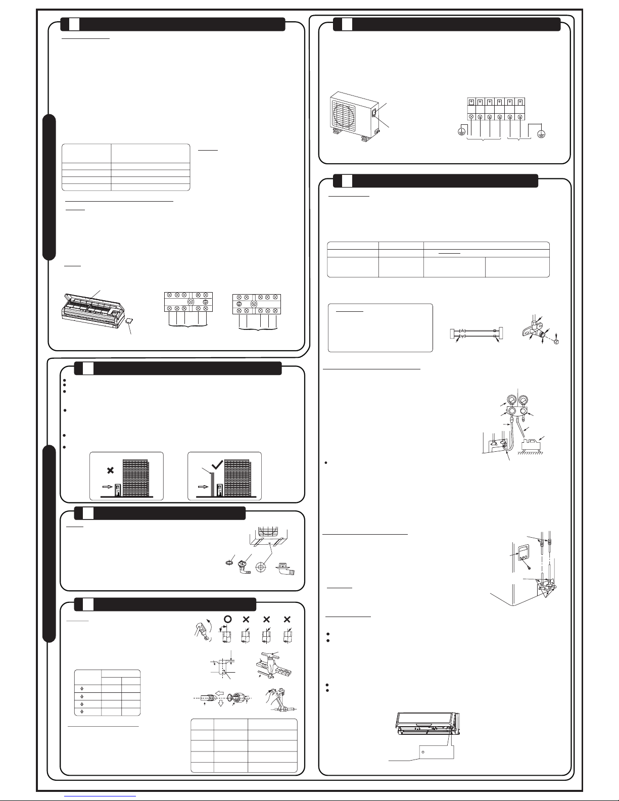
CONNECT THE CABLE TO THE OUTDOOR UNIT
CAUTION
1
Indoor unit
check point
D
B
C
A
Outdoor unit
check point
Cover
NOT E:
Befor e perfo rming a ny elec trica l work, t urn off th e main power to th e system.
1. The ins ide and outsid e connecting c able can be conn ected withou t removing the f ront grille.
2. The ind oor power cord t ype is H05VV-F or H0 5V2V2-F, the outdo or power cord an d
inter conne cted co rd type i s H07RN -F.
3. Lift t he indo or unit p anel up , remov e the ele ctric al box co ver by lo oseni ng the sc rew.
4. Ensu re the co lour of w ires of o utdoo r unit an d the ter minal N os. are t he same t o the ind oor s
respe ctive ly.
5. Wrap th ose cables not c onnected wit h terminals wi th insulatio n tapes, so that t hey will not tou ch
any ele ctric al comp onent s. Secu re the ca ble ont o the con trol bo ard wit h the cor d clamp .
NOTE: F or the st andby c ontro l needs , the cro ss sect ion are a of cabl e conne cted to L (1), 1, 2 (N)
must be s uffici ent for the maxi mum system cur rent. The maxim um system curr ent is equal to th e sum
of indo or unit a nd outd oor uni t rated c urren t.
NOT E:
NOTE:
Pan el
Ele ctric al box
cov er
Manual c ontrol
button
AUTO/COOL
Elect ric safet y regulat ions for the init ial Insta llati on
1. If there is seriou s safety prob lem about the pow er supply, the techn icians should refu se to install
the air conditi oner and expl ain to the client unt il the proble m is solved.
2. Power volt age shoul d be in the range of 90%~110%of rate d voltage .
3. The surge prote ctor and main power switch wit h a 1.5 times capacit y of Max. Current of the
unit should be inst alled in powe r circuit .
4. Ensure the air con ditio ner is ground ed well.
5. Accordin g to the attached Ele ctric al Connec tion Diag ram locat ed on the panel of the outdoo r unit
to connect the wire .
6. All wiring must comp ly with local and nat ional ele ctric al codes and be insta lled by quali fied and
skilled ele ctric ians.
7. An all-pole disc onnec tion devi ce which has at least 3mm sep arati on distan ce in all pole and a residual
current dev ice(R CD) with the rati ng of not exceedi ng 30mA shall be incorp orate d in the fixed wiring
accordi ng to the nationa l rule.
8. An individua l branch circ uit and singl e recepta cle used only for thi s air conditi oner must be
availab le. See the follo wing tabl e for suggest ed wire sizes and fus e specifi catio ns:
El ec tr ic al work
Terminal block of indoor unit
To outdoor unit
To outdoor unit
L(1)
2(N)
S
1
Terminal block of outdoor unit
To indoor unit
Power supply
1
2(N)
S
L N
L(1)
L(1)
2(N)
S
1
or
 Loading...