

Page 1

Product description
The Signature Series Riser Monitor Module (model RM1) is an
intelligent analog-addressable device that monitors the integrity
of:
• 12 and 24 Vdc circuits
• 25 Vac circuits
• 70 Vac circuits
• Telephone riser signals
Once device address is required. Upon the loss of a signal, the
fire alarm control panel indicates an alert status. See Table 1
for a list of model numbers.
The loop controller assigns an address to the RM1
automatically. A custom address can also be assigned to the
module via laptop computer. No addressing switches are used.
Table 1: Models
Description Number
Riser monitor module GSA-RM1
SIGA-RM1
SIGA-RM1-LG
Mounting
The RM1 can be mounted in a North American 2-1/2 in (64
mm) deep 2-gang box or a standard 4 in square box 1-1/2 in
(38 mm) deep with 2-gang cover. The terminal blocks accept
12, 14, 16, or 18 AWG wire (2.5, 1.5, 1.0, or 0.75 sq mm).
Sizes 16 and 18 are preferred.
System controller compatibility
The RM1 requires the Signature loop controller. The loop
controller downloads the personality code which determines
how the module operates. The following personality codes can
be downloaded to the RM1.
Personality code 23: Riser monitor (factory default):
Personality code 23 configures the RM1 to monitor 70 Vac
audio, 25 Vac audio, or 12 Vdc and 24 Vdc risers. A trouble
condition is reported back to the panel wherever the voltage on
the riser drops below the trouble threshold.
Signature Series
Riser Monitor Module (RM1)
Note: The hardware jumper on the RM1 must be configured
for either 70 Vac or 25 Vac / 24 Vdc / 12 Vdc.
Personality code 24: Telephone riser monitor: Personality
code 24 configures the RM1 to monitor telephone risers. A
trouble condition is reported back to the panel whenever
voltage on the riser drops below the trouble threshold.
The delay time from when the device falls below the trouble
threshold to when it sends a trouble signal to the panel is user
definable in the appropriate data entry program. A delay of 5 to
75 seconds can be assigned to the device; the default delay
period is 15 seconds.
Warnings
1. Disconnect power to cabinets before installing or removing
components. Failure to do so may result in serious injury
or loss of life. Dangerous voltages may be present at the
terminals even when power is shut off.
2. This module will not operate without electrical power. As
fires frequently cause power interruption, we suggest you
discuss further safeguards with your local fire protection
specialist.
3. This module does not support conventional smoke
detectors.
Specifications
Operating voltage range: 15.2 to 19.95 Vdc
Maximum input voltages
Riser monitor: 12 Vdc + 15%, 24 Vdc + 10%,
25 Vac + 15%, 70 Vac + 15%
Telephone: 3.75 to 28 Vdc
Standby current: 175 µA
Activated current: 175 µA
Input currents
12 Vdc: 10 mA DC
24 Vdc: 10 mA DC
25 Vac: 10 mA RMS
70 Vac: 10 mA RMS
Telephone 24 Vdc: 20 mA DC
Riser loading
70 Vac: Impedance > 11 kΩ
25 Vac: Impedance > 1 kΩ
24 Vdc: Resistance > 2.4 kΩ
12 Vdc: Resistance > 1.2 kΩ
Telephone: Resistance > 1.2 kΩ, Impedance > 1.2 kΩ
Ground fault impedance: 10 kΩ
Operating environment
Temperature: 32 to 120 °F (0 to 49 °C)
Humidity: 0 to 93% RH, noncondensing at 90 °F (32 °C)
Storage temperature: -4 to 140 °F (-20 to 60 °C)
Compatible electrical boxes
North American 2.5-inch (64 mm) deep 2-gang box
Standard 4-inch (101.6 mm) x 1.5-inch (38 mm) deep
square box with 2-gang cover
Agency listings:
FM Approval only includes monitoring of the 12 and 24
Vdc circuits
Installation Sheet 01JUN07 P/N: 387347 REV: 5.0
Signature Series Riser Monitor Module (RM1) 1 / 3
Page 2

Installation instructions
Note: The RM1 is shipped from the factory as an assembled
unit; it contains no user-serviceable parts and should not be
disassembled.
To install the module:
Wire stripping guide
1/4 in (~6 mm)
1. Verify that all field wiring is free of opens, shorts, and
ground faults.
2. Make all wiring connections as shown in the wiring
diagram.
3. Write the address assigned to the module on the label
provided and apply the label to the module. Peel off the
removable serial number label from the module and apply
it to the appropriate location in the serial number logbook.
4. Using the 4-24 x 5/16 in (8 mm) self-tapping screw
provided, mount the wall plate to the module.
5. Using the four 6-32 x 1/2 in (13 mm) machine screws
provided, mount the module to the electrical box.
Note: Wire in accordance with NFPA 70 National Electrical
Code.
Strip 1/4 in (about 6 mm) from the ends of all wires that
connect to the terminal block of the module.
Caution: Exposing more wire may cause a ground fault.
Exposing less wire may result in a faulty connection.
P/N: 387347 REV: 5.0 01JUN07 Installation Sheet
2 / 3 Signature Series Riser Monitor Module (RM1)
Page 3
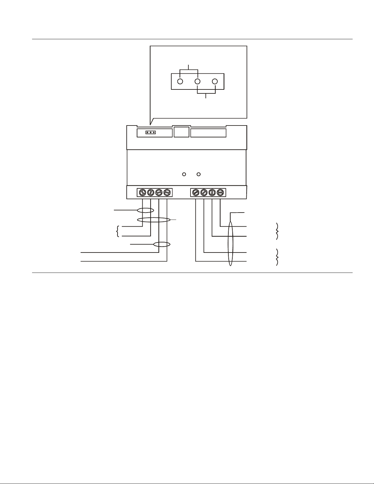
Wiring diagram
Jumper settings
12 Vdc, 24 Vdc, or 25 Vac
70 Vac
Note:
Leave the jumper out for telephone
riser operation.
JP1
[2]
[4]
12 Vdc, 24 Vdc, 25 Vac, or 70 Vac
riser from power supply or audio
amplifier (not polarity sensitive)
[2]
[1]
Telephone riser (+)
Telephone riser (-)
Notes
[1] Supervised and power-limited
[2] 12 AWG (2.5 sq mm) max; 18 AWG (0.75 sq mm) min
[3] See the Signature loop controller installation sheet for
wiring specifications
[4] Supervised and power-limited unless connected to a
nonpower-limited source. If the source is nonpowerlimited, eliminate the power-limited mark and:
• Maintain a 1/4 inch (6.4 mm) space from powerlimited wiring
or
• Use FPL, FPLR, FPLP, or an equivalent cable in
accordance with NFPA 70 National Electric Code
Wire size must be capable of handling fault current from
nonpower-limited source.
[6] [7]
Green LED
[5]
12345678
[3] [8]
Data out (-)
Data out (+)
Data in (-)
Data in (+)
To Signature device
From Signature loop controller
or previous device
[5] Active when communicating with the Signature loop
controller
[6] You cannot use the telephone riser while you use the 12
and 24 Vdc, 25 Vac, or 70 Vac riser
[7] Riser circuits are Style 4 (Class B)
[8] Data circuits are Style 4 (Class B) or Style 6 (Class A)
Installation Sheet 01JUN07 P/N: 387347 REV: 5.0
Signature Series Riser Monitor Module (RM1) 3 / 3
 Loading...