

Carrier MFQ121 User Manual
40MFC / 38MFC
40MFQ / 38MFQ
High---Wall Ductless Split System
Sizes 009 to 022
Owner's Manual
TABLE OF CONTENTS
PAGE
A NOTE ABOUT SAFETY 2...................................................................................
GENERAL 2.................................................................................................
PART NAMES 3..............................................................................................
DISPLAY PANELS 4..........................................................................................
REMOTE CONTROL 5........................................................................................
REMOTE CONTROL FUNCTIONS 6--7..........................................................................
CLEANING, MAINTENANCE AND TROUBLESHOOTING 8 -- 9.....................................................
NOTE TO EQUIPMENT OWNER:
Please read this Owner’s Information Manual carefully before installing and using this appliance
and keep this manual for future reference.
For your convenience, please record the model and serial numbers of your new equipment in the
spaces provided. This information, along with the installation data and dealer contact information,
will be helpful should your system require maintenance or service.
UNIT INFORMATION
Model # ___________________________________
Serial # ___________________________________
INSTALLATION INFORMATION
Date Installed _____________________________
DEALERSHIP CONTACT INFORMATION
Company Name: _________________________________
Address:_________________________________________
________________________________________________
Phone Number:__________________________________
Technician Name:_________________________________
________________________________________________
A NOTE ABOUT SAFETY
Any time you see this symbol in manuals, instructions and on
the unit, be aware of the potential for personal injury. There are
three levels of precaution:
DANGER identifies the most serious hazards which will result in
severe personal injury or death.
WARNING signifies hazards that could result in personal injury or
death.
CAUTION is used to identify unsafe practices which could result
in minor personal injury or product and property damage.
NOTE is used to highlight suggestions which will result in
enhanced installation, reliability, or operation.
!
PERSONAL INJURY, DEATH AND / OR PROPERTY
DAMAGE HAZARD
Failure to follow this warning could result in personal injury,
death or property damage.
Improper installation, adjustment, alteration, service,
maintenance, or use can cause explosion, fire, electrical shock,
or other conditions which may cause personal injury or
property damage. Consult a qualified installer, service agency,
or your distributor or branch for information or assistance. The
qualified installer or service agency must use
factory--authorized kits or accessories when modifying this
product.
Read and follow all instructions and warnings, including labels
shipped with or attached to unit before operating your new air
conditioner.
WARNING
GENERAL
The high wall fan coil unit provides quiet, maximum comfort. In
addition to cooling and/or heating, the high wall fan coil unit
matched with an outdoor condensing unit will filter and
dehumidify the air in the room to provide maximum comfort.
IMPORTANT: The high wall fan coil unit should be installed by
authorized personnel only; using approved tubing and accessories.
If technical assistance, service or repair is needed, contact the
installer.
The high wall fan coil unit can be set up and operated from the
remote control (provided). If the remote is misplaced, the system
can be operated from the “Auto” setting on the unit.
Operating Modes:
The high wall fan coil unit has five operating modes.
S Fan only
S Auto
S Heating (heat pump models only)
S Cooling
S Dehumidification (DRY)
Fan Only
In Fan Only mode, the system filters and circulates room air
without changing room air temperature.
Auto
In Auto mode, the system will automatically cool or heat the room
according to the user--selected set point.
Heating
In Heating mode, the system heats and filters room air.
Cooling
In Cooling mode, the system cools, dries and filters room air.
Dehumidification (DRY)
In Dehumidification mode, the system dries, filters and slightly
cools room air temperature. This mode prioritizes air
dehumidification but it does not take the place of a dehumidifier.
Remote Control
The remote control transmits commands to set up and operate the
system. The control has a window display panel that shows the
current system status. The control can be secured to a surface
when used with the mounting bracket provided.
2
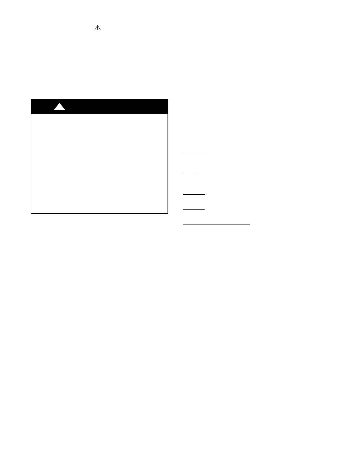
PART NAMES
■ Indoor
10
M
S
w
i
n
g
S
e
l
f
C
S
l
e
l
e
a
e
n
F
ol
I
o
l
ni
o
w
ze
M
r
e
S
m
L
a
E
r
D
t
E
y
e
F.P
.
S
i
l
e
n
■ Outdoor
1
2
1. Front panel
3
2. Air Inlet
3. Display
4. Air Filter
5. Horizontal airflow grille
6. Vertical air flow louver
4
5
Air Outlet
11
6
7
A
U
T
O
C
O
O
D
L
R
Y
HE
AT
F
A
N
HI
G
H
T
M
E
ED
M
L
P
O
o
W
d
e
O
n
/
O
f
f
F
a
n
p
T
i
m
e
r
T
u
rb
o
c
e
12
7. Interconnecting tubing
8. Control and power wiring to indoor unit
9. Service valves
10. Remote control
11. Remote control bracket
12. Self-- tapping screws
8
9
A14354
Indoor/Outdoor Unit
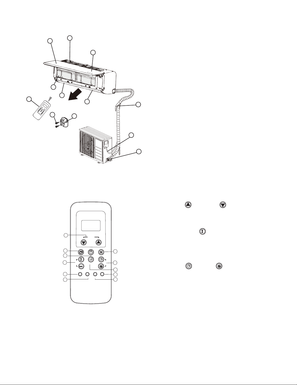
1. Temp Up /TempDown Buttons
2. Mode Button
AUTO
COOL
DRY
HEAT
1
TEMP
FAN
HIGH
MED
LOW
3. On/Off Button
4. Horizontal Swing
Button
5. Self Clean Button
On/Off
Mode
2
3
S
w
i
n
4
g
Follow Me
Self Clean
5
Ionizer
6
Smart Eye
SLEEP
Fan
LED Turbo
F.P.
Silence
7
T
im
er
8
9
10
11
6. Follow Me Button
7. Fan Button
8. Timer On
9. Sleep Button
10. Turbo Button
/TimerOff Buttons
11. LED / F.P Button
NOTE: Vertical Swing, Ionizer, Smart Eye, and Silence are not available
on this model.
A14355
Remote Control
3
 Loading...