

Page 1
ERVCCLHA, ERVCCSHB, ERVCCSVB
Energy Recovery Ventilator
Owner’s Manual
Fig. 1 -- ERVCCLHA Horizontal Unit
A07619
A05229
Fig. 2 -- ERVCCSHB Unit (Side Port)
A05330
Fig. 3 -- ERVCCSVB Unit (Top Port)
NOTE TO EQUIPMENT OWNER:
For your convenience, please record the model and serial numbers of your new equipment in the spaces
provided. This information, along with the installation data and dealer contact information will be helpful
should your system require maintenance or service.
ENERGY RECOVERY VENTILATOR
Model # _____________________________________
Serial # ______________________________________
ACCESSORIES (List type and model #)
_____________________________________________
_____________________________________________
_____________________________________________
_____________________________________________
NOTE TO INSTALLER:
This manual must be left with the equipment owner.
INSTALLATION INFORMATION:
Date Installed ________________________________
DEALERSHIP CONTACT INFORMATION:
Company Name_______________________________
Address______________________________________
_____________________________________________
Phone Number _______________________________
Technician Name _____________________________
_____________________________________________
Page 2
SAFETY CONSIDERATIONS
Recognize safety information. This is the safety--alert symbol
When you see this symbol on the unit and in instructions or
manuals, be alert to the potential for personal injury. Understand
these signal words; DANGER, WARNING, and CAUTION. These
words are used with the safety--alert symbol. DANGER identifies
the most serious hazards which will result in severe personal injury
or death. WARNING signifies hazards which could result in
personal injury or death. CAUTION is used to identify unsafe
practices which would result in minor personal injury or product
and property damage. NOTE is used to highlight suggestions
which will result in enhanced installation, reliability, or operation.
UNIT OPERATION
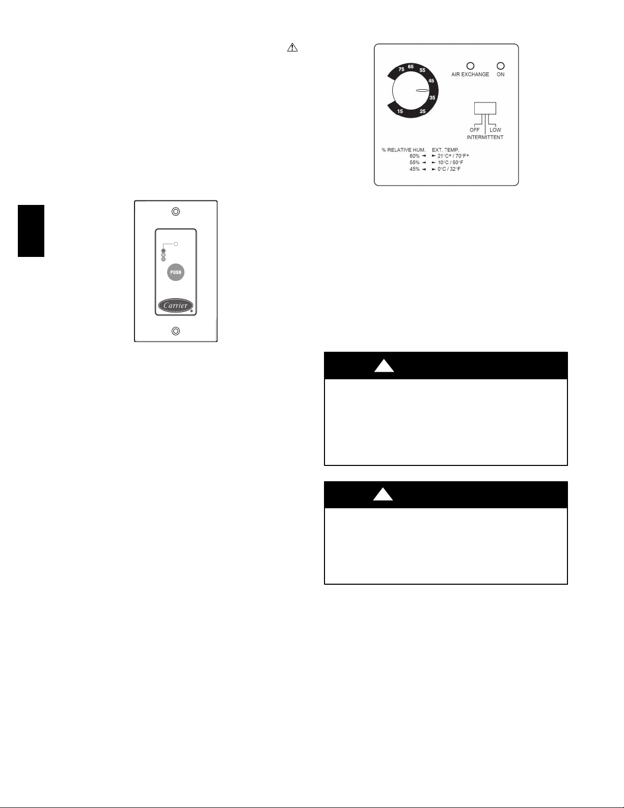
ERV with OneToucht Control
ERV
MAX
MIN
INTERMITTENT
Press “PUSH” until the desired ventilation operation is selected.
There are three selections: High, Low, Intermittent. The power
indicator light indicates which mode has been selected.
High — This mode is recommended for the removal of excess
pollutants and humidity. The ventilator will operate at its
maximum speed continuously. The power indicator light will be lit
red when this mode is selected.
Low — This mode is recommended for normal daily operation.
The ventilator will operate at its minimum speed continuously. The
power indicator light will be lit yellow when this mode is selected.
Intermittent — Thismode isrecommended whentheinsideairistoo
dryin the heatingseasonor too humidin thecoolingseason.The ventilator will operate atits minimum speed for 20 minutes per hourand
be off for 40 minutes per hour. The power indicator light will be lit
green when this mode is selected.
Off — To turn the ventilator off, press “Push” until the power indicator light is turned off.
A07622
ERV with Latent Control
A07621
Your ERV isdesigned tooperateas an integral partof yourtotalheating and cooling system.
Low Exchange Mode—If the relative humidity inside the building
is lower than selected, air exchange would occur with the outside at
high speed. If the relativehumidity level inside the building is higher
than selected,air exchange would occur outside at low speed.This ensures continuous air exchange for constant air quality.
Intermittent Mode—If the relative humidity inside the building is
higher than selected, no air exchange would occur, and the system
would turn off. If the relative humidity inside the building is lower
than selected, air exchange would occur with outside at high speed.
Thismodeis idealfor maintainingtheproperhumiditylevelwhenthe
continuous mode cannot.
!
WARNING
ELECTRICAL OPERATION HAZARD
Failure to follow this warning could result in personal injury
or death.
Before servicing system, always turn off main power to
system. Turn off accessory heater power if applicable. There
may be more than 1 disconnect switch.
!
CAUTION
PERSONAL INJURY HAZARD
Failure to follow this caution may result in personal injury.
Although special care has been taken to minimize sharp edges
in the construction of your unit, be extremely careful when
handling parts or reaching into the unit.
2
Page 3

MAINTENANCE
1. The motors are factory lubricated. Lubricating the bearings
is not recommended.
2. The core should be vacuumed every three months to
remove dust that would inhibit the energy transfer. Do not
use water. The core should only be serviced when the
outdoor temperature is between 60°F(16°C) and 75°F
(24°C) and dry.
NOTE: If the edges of the core are soft, do not try to service the
core. The air passages can be damaged and/or closed off by
handling it or trying to remove it.
3. A dirty air filter will cause excessive strain on the blower
motor. The filters in your ERV are washable and should be
cleaned every 3 months. Use a vacuum cleaner to remove
the heaviest portion of accumulated dust, then wash in
warm water.
NOTE: Do NOT clean these filters in a dishwasher or dry them
with heating appliances as they will be permanently damaged. Use
lukewarm water to clean filters. Replace filters only when they are
completely dry.
4. Regularly check the screen on the exterior intake hood and
clean as necessary.
BEFORE YOU REQUEST A SERVICE
CALL
S Check the main power disconnect switch. Verify that the circuit
breakers are ON or that fuses have not blown. If you must reset
breakers or replace fuses, doso only once. Contact yourservicing
dealer for assistance if the breakers trip or the fuses blow a second
time.
S Check for sufficient airflow. Check air filters for accumulations of
large particles. Check for blocked exhaust--air grilles or ductwork.
Keep grilles and duct work open and unobstructed.
S Check to see if the unit is calling for air exchange, or unit is in
defrost. When outdoor ambient temperature is below 23° F
(--5°C), some degree of defrost mode is possible. Defrost length
could be 5 to20 minutes,depending on temperature and settings.
Ifyour ERV stillfails to operate properly,contact yourservicingdealer.Give himyour modeland serialnumber.Withthisinformation,the
dealer will be able to correct any problems.
DOOR IS
DETACHABLE
ERV
ENERGY RECOVERY
CORE CAN BE REMOVED
BY PULLING STRAIGHT OUT
BRIEF CASE
TYPE LATCH
Fig. 4 -- Horizontal Application
FILTERS ARE
REMOVABLE BY
PULLING STRAIGHT
OUT
A99300
3
Page 4

ERV
Copyright 2010 Carrier Co rp. S 7310 W. Morris St. S Indianapolis, IN 46231 Printed in U.S.A. Edition Date: 01/10
Manufacturer reserves the right to change, at any time, specifications and designs without notice and without obligations.
4
C a t a l o g N o : O M E R V --- 0 2 C A
Replaces: OMERV--- 01CA
 Loading...