

Page 1
SERVICE &
INSTALLATION
MANUAL
CARRIER COMMERCIAL REFRIGERATION, INC.
Frozen Food
& Ice Cream
Merchandisers
CMCT
2/03 51-1021-01
Providing BEVERAGE-AIR • FRIGIDAIRE • KELVINATOR • UNIVERSAL NOLIN Products/Services
Page 2
If additional information is necessary, call the factory.
Our toll free number is 1-800-684-1199.Technical assis-
tance engineers are willing to assist you in any way possible. Office hours are from 8:00a.m. to 5:30 p.m., Eastern
Standard Time.
Important information is contained in this manual which should
be retained in a convenient location for future reference.
All data and information in this manual is subject to change without notice.
MODEL DESIGNATION INFORMATION
115V, 60HZ
PAR T # MODEL # DATA PLATE
52-2038-01 CMCT4-4 SL12/CMCT4
52-2038-03 CMCT6-4 SL20/CMCT6
52-2038-05 CMCT8-4 SL28/CMCT8
52-2038-06 CMCT10-4 SL36/CMCT10
EXPORT 220V, 50HZ
PAR T # MODEL # DATA PLATE
52-2040-01 ECMCT4-4 ECMCT4
52-2040-02 ECMCT6-4 ECMCT6
52-2040-04 ECMCT8-4 ECMCT8
Page 3

SECTION I
Introduction
Page 4
CMCT Merchandisers – Introduction
These cabinets are produced for the merchandising of frozen
food and ice cream markets. They range in size from 4' to 10'
in length. Operating ambients range from 70ºF. to 85ºF. with
cavity temperatures at load line between 0ºF. to -20ºF.
Except for routine cleaning, these cabinets will require little
maintenance. In the unusual event that repair should be
necessary, this manual presents information that is helpful in
maintaining, diagnosing, and repairing these cabinets.
INTRODUCTION 3
Page 5

TABLE OF CONTENTS
4TABLE OF CONTENTS
Due to the manufacturer’s policy of continuous quality improvement, specifications are subject to change without notice.
INTRODUCTION
Introduction .................................................................... 3
Table of Contents ............................................................ 4
Specifications & Illustrations............................................ 5
Handling & Installation .................................................... 6
Cleaning Instructions........................................................ 7
Cabinet Operation ............................................................ 7
Electrical Data .................................................................. 9
Refrigeration/Electrical Specs. (R404A)............................ 10
Refrigeration/Electrical Data Export Models...................... 11
Wiring Diagram CMCT Models 4, 6 & 8 .......................... 12
Wiring Diagram CMCT Models 10 .................................... 13
Wiring Diagram ECMCT Models 4, 6 & 8 (Export) .......... 14
Lamp Wiring Detail (Upper Raceway) .............................. 15
MAINTENANCE & REPAIR
Cabinet Temperature Control ............................................ 19
Electrical Box Layout ........................................................ 20
Defrost Timer Layout........................................................ 21
Cabinet Electrical Supply .................................................. 22
Condensing Unit Assembly .............................................. 23
Condensing Unit Layout.................................................... 24
Unit Compartment - Rear.................................................. 25
Evaporator Tubing Illustration .......................................... 26
New Lubricants ................................................................ 27
Back Pressure Valve ........................................................ 28
Light Channel Assembly .................................................. 29
Baffle Heater comp. ID & Removal .................................. 30
End Panel Breaker & Heater Removal .............................. 31
Refrig. Upper Section Comp. ID & Removal .................... 32
Upper Cross Section ........................................................ 33
Front Glass Heater Replacement ...................................... 34
Countertop........................................................................ 35
Evaporator Coil Removal .................................................. 36
Troubleshooting Guide...................................................... 38
PAR TS LISTS
CMCT Cabinet Exterior Parts ID ...................................... 40
Parts List CMCT-4, 6, 8 & 10............................................ 41
Parts List EMCT-4, 6 & 8.................................................. 42
Page 6
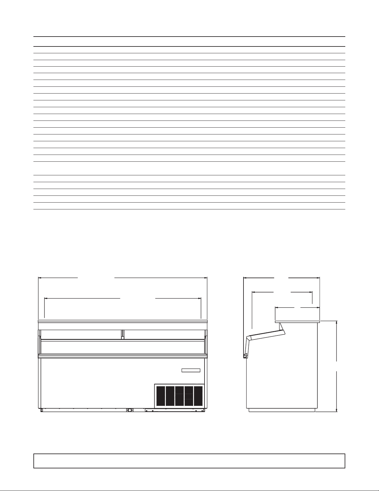
Specifications - Specifications Subject to Change without Notice.
CMCT-4 CMCT-6 CMCT-8 CMCT-10
Temperature Range 0° to -20°F 0° to -20°F 0° to -20°F 0° to -20°F
Insulation 21⁄2" Urethane Foam in Place 21⁄2" Urethane Foam in Place 21⁄2" Urethane Foam in Place 21⁄2" Urethane Foam in Place
Number of Lids 2234
Lid Construction 3/16" Glass Radiant Heated 3/16" Glass Radiant Heated 3/16" Glass Radiant Heated 3/16" Glass Radiant Heated
Capacity 11 cu. ft. 19 cu. ft. 27 cu. ft. 35 cu. ft.
Capacity (1/2 gallons) 120 225 322 435
Novelty Baskets Load Level 10 14 20 26
Capacity Novelty Baskets Total 16 24 36 48
Shipping Weight (Approx.) 486 lbs. 624 lbs. 780 lbs. 874 lbs.
Compressor Size 1/2 HP 1/2 HP 3/4 HP 1 HP
Condenser Type Bare Tube Forced Air Bare Tube Forced Air Bare Tube Forced Air Fin & Tube Forced Air
Evaporator Type Fin & Tube Gravity Coil & Cold Wall Fin & Tube Gravity Coil & Cold Wall Fin & Tube Gravity Coil & Cold Wall Fin & Tube Gravity Coil & Cold Wall
Refrigerant Type R404A R-404A R-404A R-404A
Refrigerant Control Capillary Capillary Capillary Capillary
Defrost System Electric Electric Electric Electric
Rated Amps 8.0 8.0 12 4.8 (11V0/6.7 (230V)
Electrical Specs. (V/Hz/Ph) 115/60/1 115/60/1 115/60/1 115 & 230/60/1
Power Cord 15 Amp Cord 15 Amp Cord 15 Amp Cord Conduit Connected / Max. Fuse
with 5-15P NEMA Plug with 5-15P NEMA Plug with 5-15P NEMA Plug Size 15A Min. Circuit Ampacity 15A
NSF-7 (Ice Cream Storage) Yes Yes Yes Yes
UL & CUL Listed Yes Yes Yes Yes
Interior Finish White Baked Enamel White Baked Enamel White Baked Enamel White Baked Enamel
Exterior Finish White Baked Enamel White Baked Enamel White Baked Enamel White Baked Enamel
Lighted Sign Standard Standard Standard Standard
INTRODUCTION 5
481/16 (CMCT4)
721/16 (CMCT6)
961/16 (CMCT8)
1201/16 (CMCT10)
3/4 (CMCT4)
42
663/4 (CMCT6)
783/4 (CMCT8)
114 3/4 (CMCT10)
INSIDE
32
9/16
253/4
INSIDE
19
38
3/4
Page 7

FREIGHT DAMAGES AND SHORTAGES
The cabinet was inspected and
packaged at the factory, and should
arrive in excellent condition.The transportation company
or other parties involved in the shipment are responsible
for loss and/or damage. Always make an inspection
before and after uncrating. Inspect the crated unit(s)
before locating (preferably at the point of unloading by
the transportation company).
INSPECTING FOR DAMAGES
Always use care when removing shipping
tape, blocks, pads, hardware or other material
until you are satisfied that the unit is completely operational.
Check the cartons or containers. If these are damaged
in any way, open them and inspect the contents in the
driver’s presence. If damage is detected:
1. Have the driver note the nature and extent of the
damage on the freight bill.
2. Notify the transpor tation company’s office to request
an inspection. Carrier claim policies usually require
inspections to be made within 15 days of delivery.
3. If damage is noticed, file a claim with the transpor ta-
tion company.
FILING A CLAIM
File a claim for loss at once with the transportation
company for:
A. A cash adjustment; B. Repairs; or C. Replacement
When filing your claim, retain all packaging materials
and receipts.
HANDLING THE CABINET
The refrigeration system of the cabinet is
designed to operate with the cabinet located
on a level surface. Do not tilt the cabinet more than
10° to any side. If the cabinet must be tilted on an
angle for handling or moving purposes, allow it to sit in
an upright position 30 minutes prior to starting.
CHOOSING A LOCATION
This model cabinet should be situated to allow proper air
circulation. Cabinets require a 2" minimum clearance
behind for proper air circulation.
The cabinet must be installed on a sturdy, solid, level
floor.
The cabinet must be located so it can be plugged or
wired into a properly grounded three-prong electrical
outlet of 115/220 volt, 60 hz.The electrical outlet should
not be controlled by a wall switch which might be turned
off accidentally.
UNCRATING THE CABINET
The cabinet should be moved as close as possible to
the operating location before removing crate base. Be
sure to follow the steps in the “INSPECTING FOR
DAMAGES” instructions.
INSTALLING THE CABINET
After removing the skid from the cabinet, slide cabinet
into location.Level cabinet to insure proper draining of
the defrost water.
To meet NSF requirements, these cabinets must be
sealed to the floor with an NSF or FDA approved
sealant.
Remove the front grill from cabinet. Remove front hold
down bolts and pull unit out of cabinet. Remove shipping band from compressor.Be sure that the compressor “floats” freely on the compressor springs. Check
refrigeration lines to see that they are “free” and no
damage was done in shipping.Check fan blade for free
operation.
Check voltage and amp draw on the serial plate to
determine proper fuse and line size.Voltage should be
checked at the compressor terminals as the compressor is starting, to determine if there is excessive “voltage drop.” This voltage drop should not exceed 10% of
the rated compressor voltage. If the voltage reads 115
or 230 with no load and it drops below 103 or 208 when
the compressor tries to start, it is an indication that the
supply wiring is too small in size or too long in length.
It is recommended that a separate circuit be run for each
cabinet to prevent the possibility of another appliance
blowing a fuse causing subsequent loss of product.
SECTION I – HANDLING & INSTALLATION
6 INTRODUCTION
NOTE:
IMPORTANT:
NOTE:
Page 8

CLEANING INSTRUCTIONS
CLEANING THE CABINET EXTERIOR
Wipe the exterior occasionally with a cloth dampened in
mild detergent water; rinse, and wipe dry with a soft,
dry cloth. Do not use abrasive or caustic cleaners or
scouring pads.
CLEANING THE CONDENSER
Periodic cleaning of the condenser can be easily
accomplished by brushing the coils with a soft brush
and/or using a vacuum cleaner with a brush attachment.
Be sure that dirt, dust, and a collection of other debris
do not build up to a point that air circulation through the
condenser is restricted.
CLEANING THE STORAGE COMPARTMENT
1. Remove product and store it in another suitable cab-
inet, if possible. Be sure to prevent spoilage of the
product which may occur if it is left at room temperature.
2. Turn OFF the thermostat and unplug the cabinet.
3. Defrost completely prior to cleaning.
4. Wash the entire interior storage area with warm
water and baking soda solution — about a tablespoon of baking soda per quart of water.Rinse thoroughly with clean water and wipe dry.
5. A drain hose is provided. Connections are made to
fit a standard garden hose for ease of draining water
from inside of the tank area.
IMPORTANT:
Do not use any objects or cleaners which may leave
residues, odors, or particles. Avoid the use of strong
chemicals or abrasive cleaners which may damage the
interior surfaces and contaminate product within the
storage area.
6. Be sure to correctly plug in to cabinet, set the tem-
perature control, and allow time for cooling of the
storage area before storing product.
DESCRIPTION OF REFRIGERATION
SYSTEM: CONDENSING UNIT
All CMCT cabinets are equipped with Copelametic
compressors utilizing 404A refrigerant:
1/2 HP on the CMCT-4 and CMCT-6
3/4 HP on the CMCT-8
1 HP on the CMCT-10
A back pressure valve is used to protect the compres-
sor against excessive pressures during initial cabinet
start-up and upon termination of the defrost cycle. This
valve is factory pre-set to limit the crankcase pressure
to 10# and should not be changed.
CABINET OPERATION
REFRIGERATION CYCLE:
Refrigeration is accomplished by both a “wrap-around”
tank coil and fin coil. This tank coil consists of several
passes of copper tubing wrapped completely around the
tank or product compartment.The fin coil located behind
the light fixture serves two purposes — it creates a blanket of cold air over the product and collects moisture in
the form of frost from the warm air entering the cabinet,
thus reducing frost collection on the tank coil.The refrigerant enters the top of the tank coil first and progresses
downward to the bottom of the tank;from there it enters
the top of the fin coil and again downward. By circuiting
the refrigeration in this manner, it assures the fin coil of
being the coldest part of the system.
DEFROST CYCLE:
Because of the large size and fin arrangement, the
CMCT fin coils have the ability to collect a large amount
of frost before becoming bloc ked.These f eatures permit
the CMCT cabinets to operate on one defrost cycle per
24 hours, thus reducing product shock to the ice cream.
The fin coil and drain pan are defrosted with one 4-
pass heater located on the underside of the evaporator
assembly. The back pass of the heater lays in the drain
trough which slopes from left to right along the back
edge of the drain pan.
WARNING:
To avoid the possibility of an electrical shock, turn OFF
thermostat and unplug the electrical cord of the cabinet
before cleaning or touching electrical connections or parts.
INTRODUCTION 7
Page 9
Defrosting is initiated by the time clock and terminated
by a temperature thermostat set to close at 76°F. When
this thermostat closes, it energizes a solenoid in the
time clock which in turn trips the clock mechanism off
defrost. Should this ther mostat fail to close, the defrost
cycle will be terminated by the failsafe pin on the time
clock (set at 40 minutes).
As an additional safety feature , the temper ature limiting
thermostat is wired in series with the defrost heater.
This thermostat will also open the heater circuit when
the top coil reaches 76°F. should any malfunction of the
defrost thermostat occur.
Any time the system has been opened and
exposed to the atmosphere, a new drier
should be installed, system completely evacuated, and
recharged to the specified refrigerant and amount listed on the serial plate located inside the unit compartment on the left wall.
DO NOT ATTEMPT CHARGING BY
PRESSURES ALONE!! Charge is
very critical! Charging should be accomplished by
means of weighing, or the use of a charging cylinder.
NOTE:
IMPORTANT:
8 INTRODUCTION
Page 10
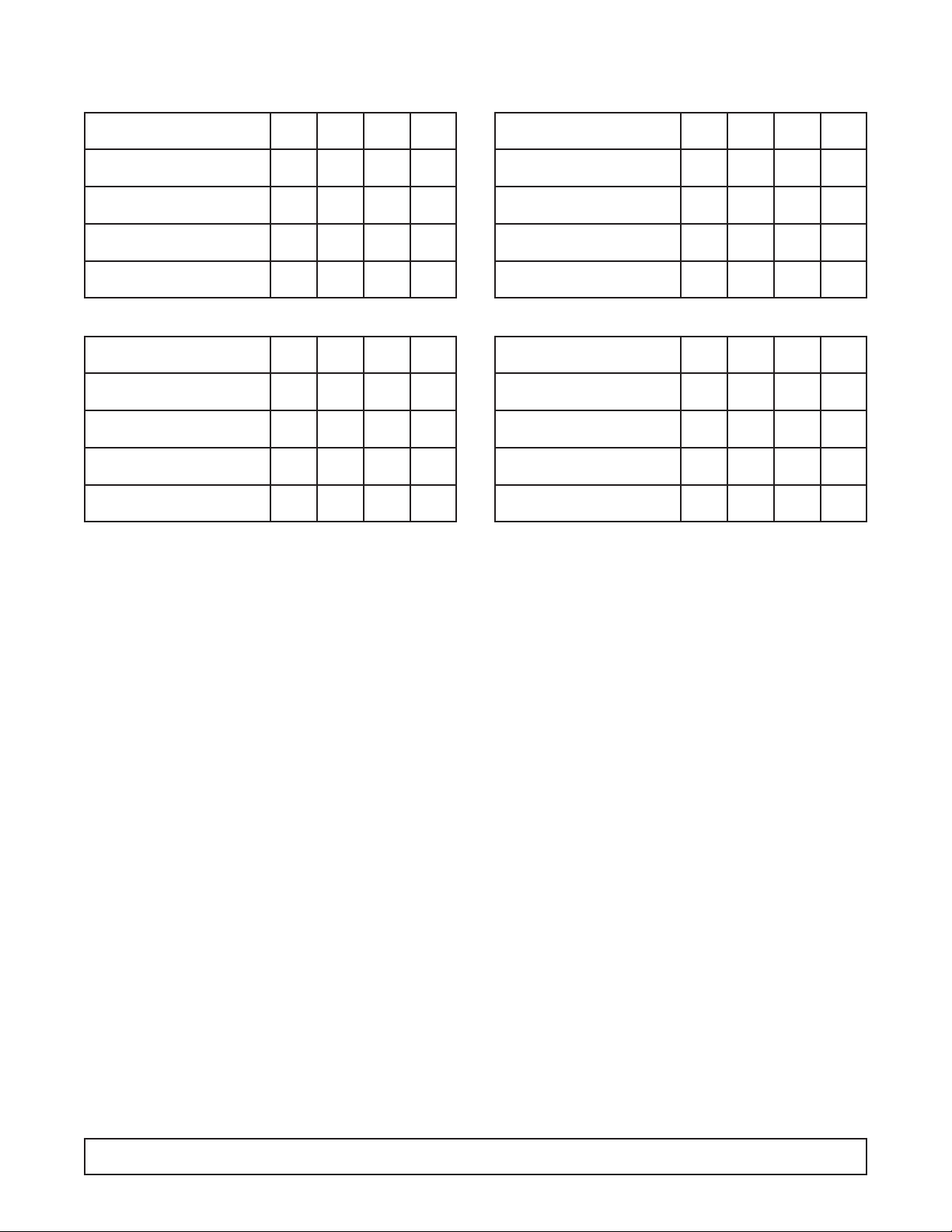
CMCT ELECTRICAL DATA
CMCT-4 OHMS WATTS AMPS VOLTS
Def. Heater on Bottom side
24.7 582 4.8 120
of Top Coil
Control Bellows Heater below
1600 9 .075 120
Def. Controls
End Breaker Heater behind
960 15 .12 120
each End Breaker
Glass Heater around
262 56 .46 120
Front Glass
CMCT-8 OHMS WATTS AMPS VOLTS
Def. Heater on Bottom side
11.8 1200 10 120
of Top Coil
Control Bellows Heater below
1600 9 .075 120
Def. Controls
End Breaker Heater behind
960 15 .12 120
each End Breaker
Glass Heater around
134 107 .89 120
Front Glass
CMCT-6 OHMS WATTS AMPS VOLTS
Def. Heater on Bottom side
15.9 904 7.5 120
of Top Coil
Control Bellows Heater below
1600 9 .075 120
Def. Controls
End Breaker Heater behind
960 15 .12 120
each End Breaker
Glass Heater around
175 82 .68 120
Front Glass
CMCT-10 OHMS WATTS AMPS VOLTS
Def. Heater on Bottom side
3.38 1561 6.7 230
of Top Coil
Control Bellows Heater below
1600 9 .075 120
Def. Controls
End Breaker Heater behind
960 15 .12 120
each End Breaker
Glass Heater around
190 132 1.1 120
Front Glass
INTRODUCTION 9
Page 11
10 INTRODUCTION
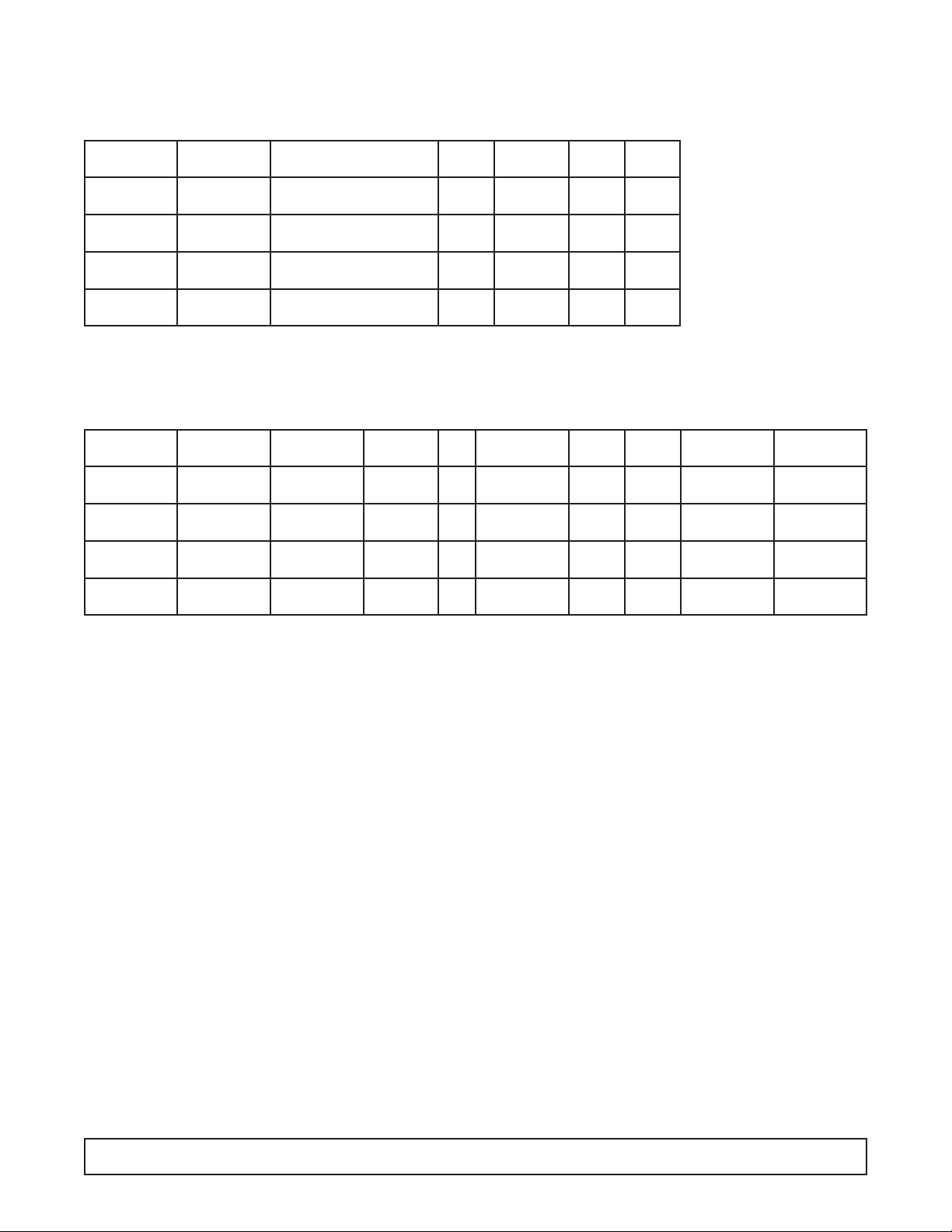
REFRIGERATION/ELECTRICAL SPECIFICATIONS
CMCT (404A)
CABINET START RUN
MODEL MFG. MODEL HP VOLTS AMPS AMPS
CMCT-4 Copeland KAGB-005E-IAA-222 1/2 115 45 8.0
CMCT-6 Copeland KAGB-005E-IAA-222 1/2 115 45 8.0
CMCT-8 Copeland KAJB-007E-IAA-222 3/4 115 59 12.0
CMCT-10 Copeland KALB-010E-CAV-221 1 230/208 33.5 8.1
REFRIGERATION CYCLE (80° Ambient)
CABINET REFRIG. DEFROST CAP. CONTROL CAVITY
MODEL CYCLE CYCLE REFRIG. OZ. TUBE SUCT. DISCH. SETTING TEMP.
CMCT-4 8.0 - 115V 6.8 - 115V 404A 22 8' x .042 ID 2# 225# No. 7 -22°F
CMCT-6 8.0 - 115V 8.4 - 115V 404A 23 8' x .042 ID 5# 223# No. 7 -19°F
CMCT-8 12.0 - 115V 12.0 - 115V 404A 27 7' x .049 ID 2# 228# No.7 -22°F
8.1 - 230V 6.7 - 230V
CMCT-10 404A 29 7' x .054 ID 2# 223# No. 7 -27°F
4.8 - 115V 4.8 - 115V
NOTE: Refer to Data plate for refrigerant type and charge.
Condenser Fan ............G.E. 5KSM51GG37845 or Temperature Control ........RANCO A10-4491-00
5KPM51BL-40466 (Reversible Motor)
230 - V.E.M.S. ESP-L35-EM2 Back Pressure Valve ............Sporlan 10# setting
CRO-4-0-20
Time Clock..............115 Paragon 145-00B (24 Hr.) CRO-6-0-60 (CMCT-10)
230V Paragon 145-20B (24 Hr.)
Page 12
INTRODUCTION 11
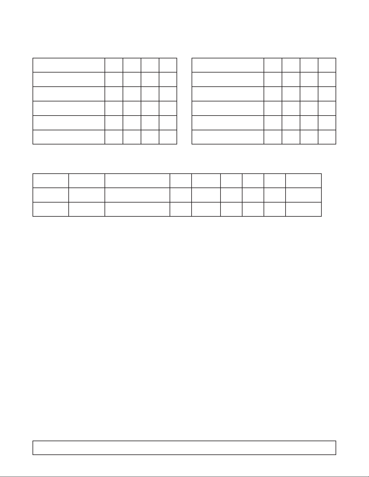
ECMCT REFRIGERATION/ELECTRICAL DATA
Export Models (R-404A)
ECMCT-4 OHMS WATTS AMPS VOLTS
Def. Heater on Bottom side
72.4 582 2.7 215
of Top Coil
Control Bellows Heater below
5375 9 .04 215
Def. Controls
End Breaker Heater behind
3071.4 15 .07 215
each End Breaker
Glass Heater around
826.9 56 .26 215
Front Glass
Heated Glass Lid
41.3 14 .58 24
(each)
ECMCT-6 OHMS WATTS AMPS VOLTS
Def. Heater on Bottom side
51 904 4.2 215
of Top Coil
Control Bellows Heater below
5375 9 .04 215
Def. Controls
End Breaker Heater behind
3071.4 15 .07 215
each End Breaker
Glass Heater around
565.8 82 .38 215
Front Glass
Heated Glass Lid
26.1 22 .92 24
(each)
COMPRESSOR AMPERAGE
CABINET RUN CAP.
MODEL MFG. MODEL HP VOLTS LRA AMPS OZ. TUBE
ECMCT-4 Copeland KAJB-010E-CAV 1 200 40 8.0 20 8' x .042
ECMCT-6 Copeland KAJB-010E-CAV 1 200 40 8.0 25 8' x .042
Page 13
12 INTRODUCTION
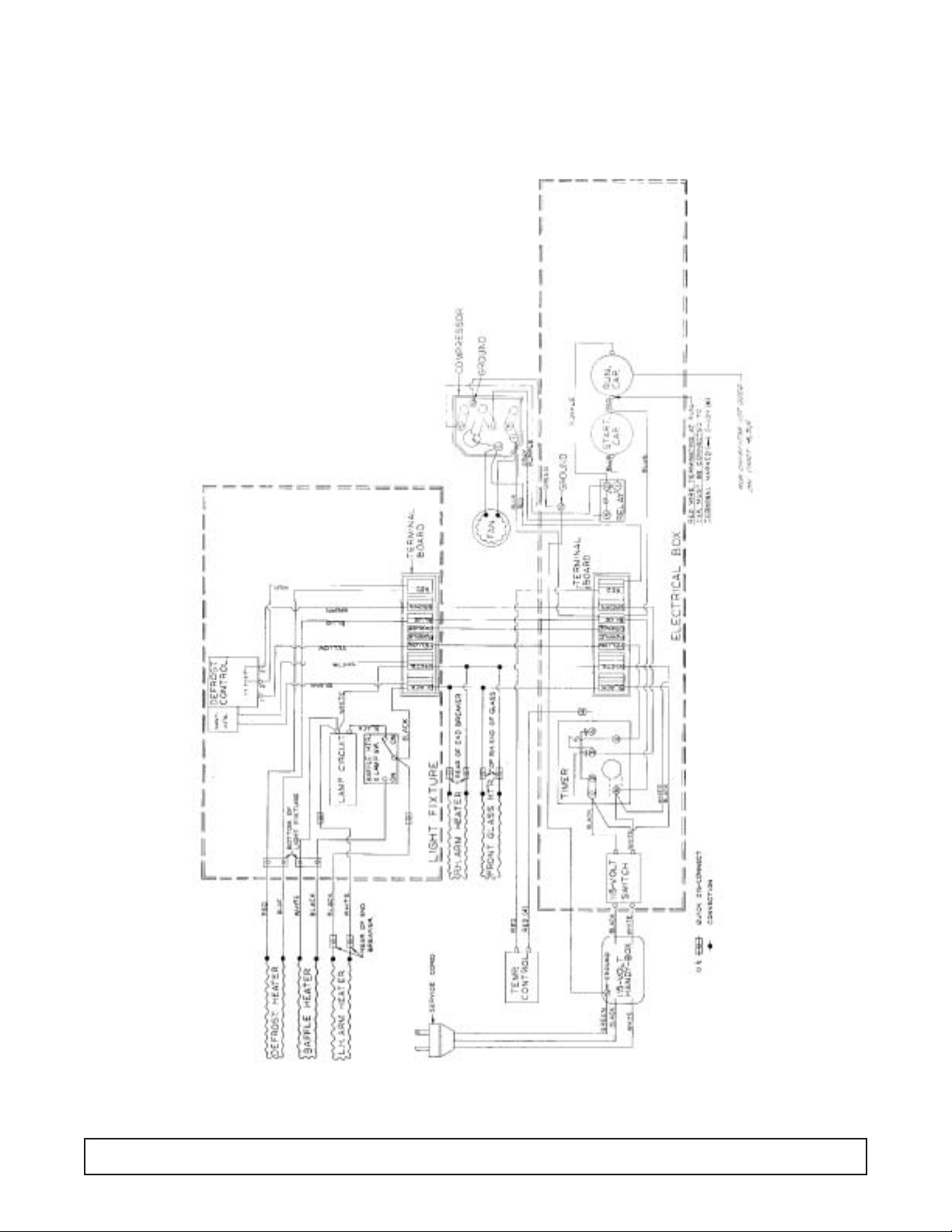
WIRING DIAGRAM – 00-1667-00
CMCT-4, 6, & 8
Page 14

INTRODUCTION 13
WIRING DIAGRAM – 00-1670-00
CMCT-10
Page 15

14 INTRODUCTION
WIRING DIAGRAM – 00-1934-00
ECMCT-4, 6, & 8 (Export Models)
Page 16

INTRODUCTION 15
LAMP WIRING DETAIL –
Upper Raceway (Typical)
Page 17

SECTION II
Maintenance & Repair
Page 18

MAINTENANCE & REPAIR 19
CABINET TEMPERATURE CONTROL
Disconnect the power supply before
servicing the cabinet.
Remove the front grill.
The control is located in the machine compartment in
the upper righthand corner, just above the electrical
box. Control settings are numbered from #1 (warmest)
to #7 (coldest) positions.
The control capillary is inser ted in a copper bulb well
just to the right of the control. The well is approximately 20" long and is secured to the cold wall evaporator.
The control reacts to the evaporator temperature which
is approximately -40°F in order to maintain a cavity
temperature of -20°F.
CAUTION:
COLD OUT NORMAL OUT NORMAL IN WARM IN
-30°F -23°F -15°F -2°F
TERMINALS: .25 QUICK CONNECT TAB
CAP TUBE LENGTH: 24"
1. Temperature Control
2. 115V Cabinet Power Switch (115V models)
3. 230V Cabinet Power Switch (230V models)
11
11
22
22
33
33
Page 19

ELECTRICAL BOX LAYOUT
Disconnect the power supply before
servicing the cabinet.
The electrical box can be accessed by removing the
front grill.
The electrical box can be pulled out for component
troubleshooting.
The following components are located within the box.
CAUTION:
1. Defrost Timer - 1/24 Hours 5. Main Terminal Board
2. Run Capacitor 6. 115V Power Supply Switch (115V models)
3. Start Capacitor 7. 230V Power Supply Switch (230V models)
4. Potential Relay
11
11
22
22
33
33
44
44
55
55
66
66
77
77
20 MAINTENANCE & REPAIR
Page 20

DEFROST TIMER LAYOUT
After the cabinet is connected to proper voltage supply,
the time clock should be set to the correct time of day
by turning the inner knob counterclockwise until the
correct time is opposite the time indicator on the clock.
The time clock is set to go into defrost once every
24 hours. This defrost occurs at midnight. Under
extreme humidity conditions it might be necessary to
add a second defrost.
MAINTENANCE & REPAIR 21
Page 21

CABINET ELECTRICAL SUPPLY
The connection points can be accessed by removing
the rear grill. Models CMCT-4 up through CMCT-8 have
115V service cords. CMCT-10 is 230V, hard wire connected.
These cabinets must be on a dedicated circuit unto themselves. Failure to do so could
result in loss of product.
Wiring and connections in power
supply system must meet all applicable (local and national) electrical codes. Consult these
codes for wire lengths and sizes prior to cabinet installation.
The wiring diagram should be consulted before
attempting any electrical service.
NOTE:
IMPORTANT:
24 MAINTENANCE & REPAIR
Page 22

This product utilizes the pull out feature on its low temperature applications.This is to aid service personnel in
the event service is needed.
Disconnect the power supply before
servicing the cabinet.
1. Remove front grill.
2. Remove two (2) hold down bolts that are located in
the front base rail. Pull unit out for service.
CONDENSING UNIT ASSEMBLY
CAUTION:
MAINTENANCE & REPAIR 23
Page 23

CONDENSING UNIT LAYOUT
24 MAINTENANCE & REPAIR
Page 24

UNIT COMPARTMENT – REAR
CMCT-10 models still use fin and tube
condensers.
NOTE:
11
11
22
22
33
33
44
44
1. Accordian Coil
2. Process Tube Evaporator
3. Suction Line
4. Cap Tube Inlet
MAINTENANCE & REPAIR 25
Page 25

EVAPORATOR TUBING ILLUSTRATION
EVAPORATOR TANK WRAP –
RH SIDE VIEW:
Evaporator inlet tube
on top row.
1. Tank Wrap Inlet
2. #2 Pass
3. #3 Pass
4. Thermostat Bulb Well
5. Condensate Drain
NOTE:
TANK WRAP – FRONT SIDE
6. #1 Pass
7. #2 Pass
8. #3 Pass
9. #4 Pass
10. #5 Pass
Upper evaporator coil
connections are on the
top, left back wall.
NOTE:
EVAPORATOR TANK WRAP –
RIGHTHAND REAR OF CABINET:
Capillary tube and heat exchange are
foamed in place. Three lines exit the
cabinet shell:
11.
1
⁄4" Process Line
12. Capillary T ube
13. Suction Line
If the capillary tube should ever become
restricted, the 1⁄4" process tube can be
substituted as an evaporator inlet.
26 MAINTENANCE & REPAIR
11
11
22
22
33
33
44
44
55
55
66
66
77
77
88
88
99
99
111100
00
111111
11
111122
22
111133
33
Page 26

NEW LUBRICANTS
In switching from refrigerant 502 to refrigerant 404A,
the compressor lubricants had to be changed. Oils
used in the compressors in the past were mineral
based. The new oils used are polyol esters. Special
consideration must be made when handling these oils.
Processing procedures must be more rigorous to avoid
absorbing moisture. Also, P.O.E.’s are better solvents
which means they will dislodge and carry debris
through a system to a far greater extent than do mineral oils. The oil used in Copeland compressor is Mobil
Artic EAL-22-CC.
MAINTENANCE & REPAIR 27
Page 27

BACK PRESSURE VALVE – #1
These models are equipped with a back pressure
valve. The purpose of this valve is to limit the suction
pressure at the compressor during initial cabinet start
up and start up after a defrost cycle.This valve is set at
10 PSIG and should not be changed.To check this
setting it is necessary that the pressure on the inlet side
or evaporator side of the valve be above 10 PSIG. Put
cabinet into defrost cycle to obtain high-low side pressure. With gauge installed on suction service valve,
check valve setting after cabinet comes off the defrost
cycle.Allow the compressor to run a few minutes before
determining correct setting. (CRO6 shown)
11
11
28 MAINTENANCE & REPAIR
Page 28

LIGHT CHANNEL ASSEMBLY – Component Identification
Disconnect the power supply before
servicing the cabinet.
Wiring from the pull out electrical box is connected via
a wiring harness to the upper lighting channel which
houses the following components:
CAUTION:
1. Product Reflector 4. Light Ballast
2. Defrost Termination Control 5. Lamp Receptable & Starter
3. Upper Terminal Board 6. Ambient T emper ature Compensator
11
11
22
22
33
33
44
44
55
55
66
66
MAINTENANCE & REPAIR 29
Page 29

BAFFLE HEATER COMPONENT IDENTIFICATION
& REMOVAL INSTRUCTIONS
1. Baffle Heater
2. Light Switch
3. Light Receptacle – Lefthand side
When light switch is ON, baffle heater
is de-energized.
NOTE:
Disconnect the power supply before
servicing the cabinet.
The baffle heater is located just behind the light fixture
at the warm air intake to coil.
The baffle can be accessed by removing screws located
at the bottom edge of V baffle.The heater is attached at
the back side of the V baffle with self-adhesive tape.
The heater resistance can be checked by unplugging
the heater at the plug-in connector on the lefthand end
of the light channel.The heater is only energized when
the light is turned OFF.
CAUTION:
11
11
11
11
22
22
33
33
30 MAINTENANCE & REPAIR
Page 30

END PANEL BREAKER & HEATER REMOVAL
Disconnect the power supply before
servicing the cabinet.
1. Remove eight (8) screws in the end panel breaker
(A) and pull breaker down and out.
2. Disconnect heater leads from end panel breaker
heater (A) and pull end panel breaker out.
3. To remove end panel breaker heater, remove tape.
CAUTION:
The heater is taped to the back side of the side arm breaker.
NOTE:
AA
AA
BB
BB
MAINTENANCE & REPAIR 31
Page 31
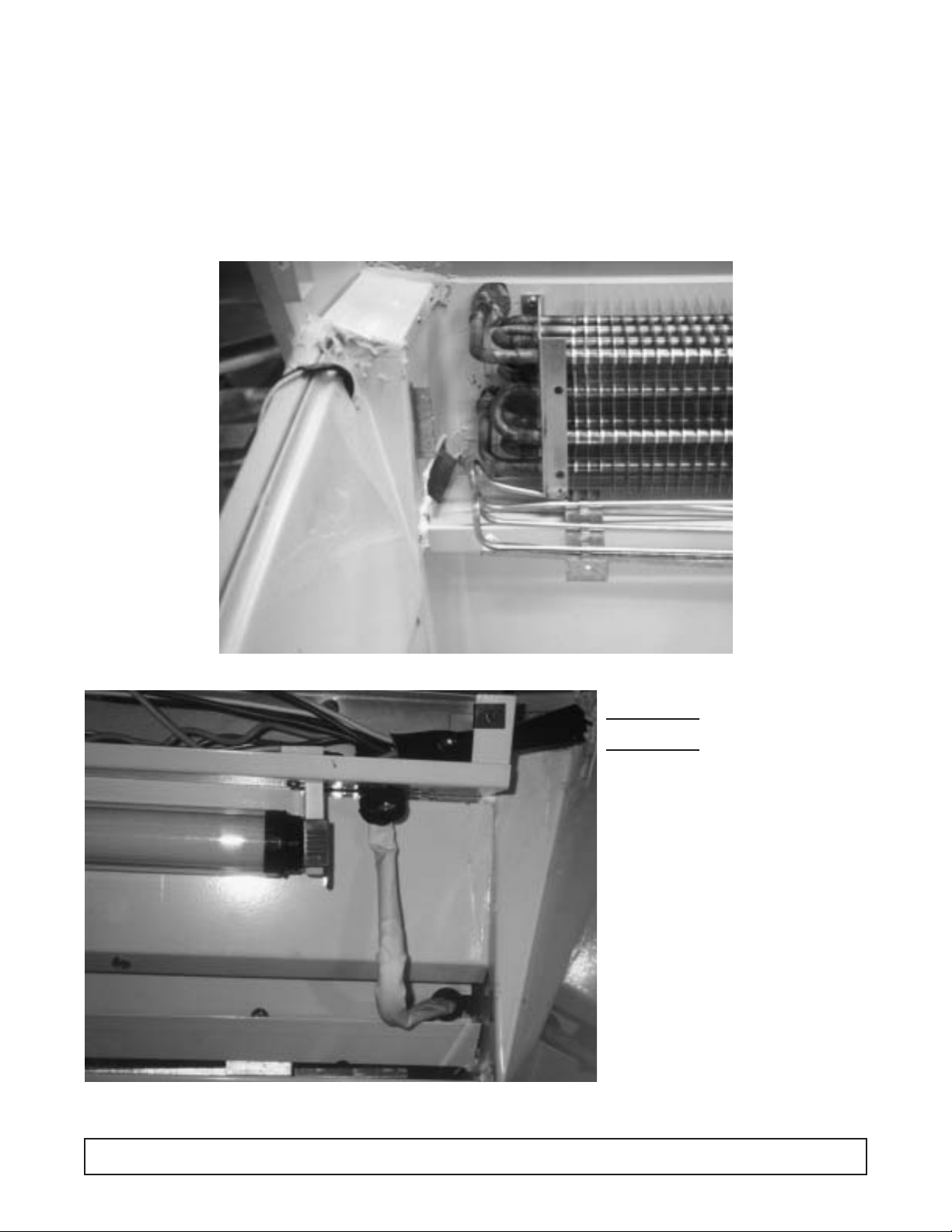
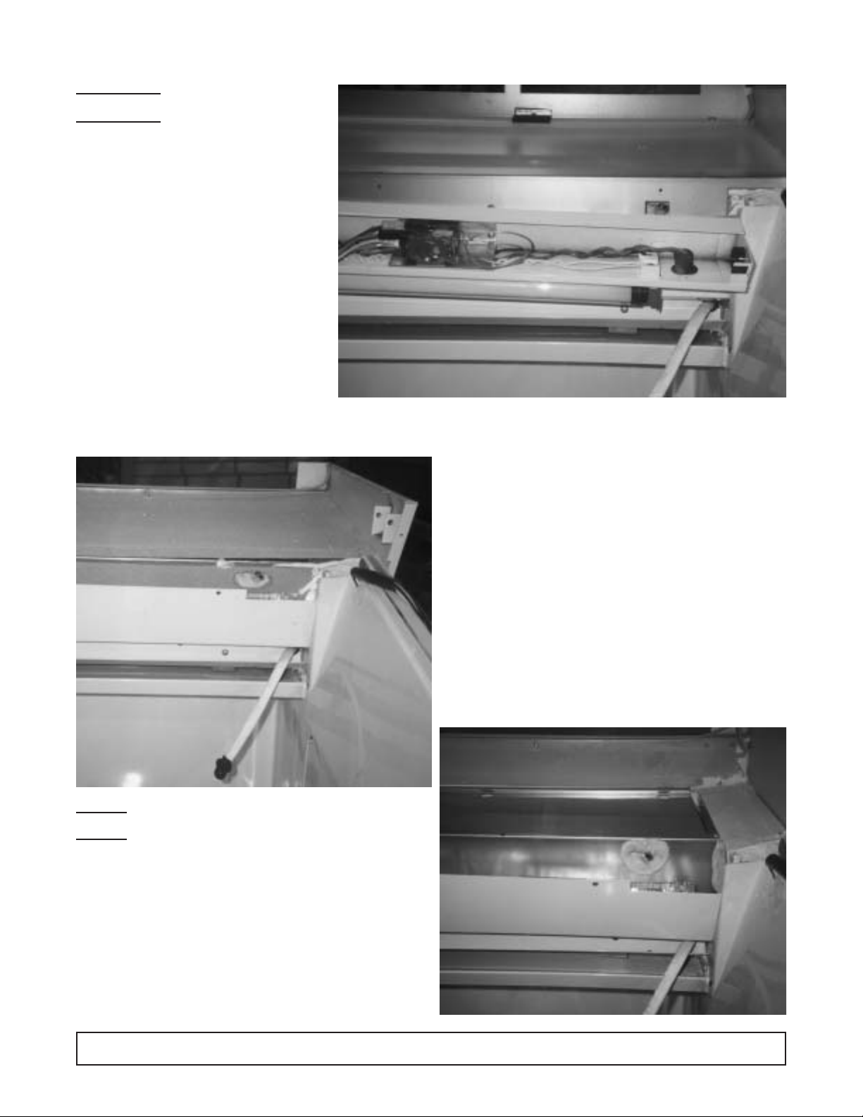
REFRIGERATED UPPER SECTION COMPONENT
IDENTIFICATION & REMOVAL INSTRUCTIONS
1. Defrost Heater Lead Connection 4. Defrost Heater
2. Air Baffle 5. Defrost Heater Retainer Bracket
3. Upper Fin Coil 6. Fro n t Co il Housing Cover Bracket
REMOVAL INSTRUCTIONS:
Disconnect the power
supply before servic-
ing the cabinet.
1. Disconnect the defrost heater
leads located on the lower righthand side of the lamp channel –
Figure #1.
2. Remove the air diverter shown as
Figure #2. This will expose the
defrost heater rack which is mounted to the evaporator fin coil.Heater
and rack assembly can now be
removed.
3. Reattach new heater to rack.
NOTE: Last pass of the defrost
heater must lay down in the drain
trough.
4. Reassemble in reverse order.
CAUTION:
11
11
22
22
33
33
44
44
55
55
66
66
32 MAINTENANCE & REPAIR
Page 32

UPPER CROSS SECTION – CMCT Models
Page 33

FRONT GLASS HEATER REPLACEMENT
Disconnect the power supply before
servicing the cabinet.
Photograph shows the electrical connection between
the cabinet and the front glass heater.
CAUTION:
REMOVAL OF FRONT GLASS HEATER
AND/OR END TRACK:
1. Remove glass lids.
2. Remove side arm trim (A) at both sides per detail
‘A’.
3. Remove three (3) screws in vertical trim post (F)
and pull vertical trim post forward.Typical at both
ends.
4. Remove three (3) screws in end track (B). Pull
track forward and lift up.Typical both ends. (Not
necessary for glass removal.)
5. Remove two (2) screws in the front of center
track (G) and swing center track from dotted line
position to solid line position.
6. Remove two (2) screws (one each end) on glass
rail (C) and lift glass rail straight up.
7. Pull top of front glass (D) forward and lift glass
and heater (E) up.
8. To remove end track only, execute the first four
steps.To remove front glass heater, execute the
first seven steps, omitting step number 4.
NOTE: Pay close attention to the way the heater
wire is arranged on the front glass when replacing.
34 MAINTENANCE & REPAIR
Page 34

CMCT Models
The countertop can be raised in order to service various
interior components, as shown below.
1. Product Reflector 4. Upper Electrical Component Housing
2. Defrost Heater Plug 5. Righthand Ar m Heater Leads
3. Lamp
MAINTENANCE & REPAIR 35
11
11
22
22
33
33
44
44
55
55
Page 35
EVAPORATOR COIL REMOVAL
Disconnect the power
supply before servicing
the cabinet.
A. Raise up the counter top.
B. Remove screws along the back wall
of the sub top.
C. Remove the high air intake baffle
located on the righthand side of the
sub top.
D. Remove the cabinet lids and lid rails.
E. Remove the screws that hold the
light channel to the sub top.
F. Pull the defrost ter mination bulb out
of the evaporator coil bulb well. Lift
the sub top up and out of the cabinet.
CAUTION:
1. Defrost Termination & High Limit Control 3. Defrost Heater Receptacle
2. Defrost Termination Bulb Well 4. Sub Top
G. Lift the insulation up and out of the cabinet.Do not
break.This will expose the coil housing cover.This
cover is attached by three screws, one on each
end and one at the rear on the top.
5. Upper Coil Insulation
6. V Baffle Insulation
7. V Baffle Front
36 MAINTENANCE & REPAIR
Reseal bulb well and coil cover with permagum
as shown.
8. Coil Cover
9. V Baffle Heater
NOTE:
11
11
22
22
33
33
44
44
55
55
66
66
77
77
88
88
99
99
Page 36

EVAPORATOR COIL REMOVAL – continued
10. Sub Top
11. Air Diverter
12. Defrost Termination Bulb Well
The view below illustrates the evaporator coil and
tube connections on the lefthand end of the cabinet. Take care when reinstalling the coil housing
cover. Reseal areas where moisture could migrate
down into the coil area. This coil area runs at a
temperature of -40°F.
13. Upper Coil Inlet 14. Upper Coil Outlet
MAINTENANCE & REPAIR 37
111100
00
111111
11
111122
22
111133
33
111144
44
Page 37

CMCT TROUBLESHOOTING GUIDE
The following is a guide to aid in the proper diagnosing
of service problems.
High Head Pressure & High Back Pressure
1. Air in system.
2. Defective fan motor or fan blade dragging on con-
denser shroud.
3. Defrost heater on during refrigeration cycle due to
heater going to ground or defective time clock.
4. Refrigerant over charge.
5. Blocked condenser (dirty)
Low Back Pressure & Low Head Pressure
1. Defective back pressure valve—check for proper
setting as described under “Back Pressure Valve.”
2. Shortage of refrigerant—place a temperature indicat-
ing device on outlet of top coil (lower lefthand side of
coil).Temperature should read within 3 to 4 degrees of
low side pressure taken at the compressor suction
service valve. Add gas slowly until these conditions
are obtained or remove charge with certified recovery
equipment, and recharge with correct charge.
3. Cap tube plugged due to moisture or dirt.
Pressures Normal – Cabinet Warm
1. Top coil blocked with frost—see corrective mea-
sures under “Coil Block With Frost.”
2. Refrigerant under charge. Due to the fact that it
takes a considerable amount of under charge bef ore
it has any great effect on pressures and inaccuracy
of gauges it is possible to have normal pressures
and yet have an under charge of refrigerant. This
under charge will “starve” the top coil and seriously
affect cabinet temperature. To determine correct
charge see #2 under “Low Back Pressure … .”
Coil Blocked With Frost
1. Bad timer or timer motor.
2. Bad drafts in store caused by heating or air condi-
tioning fans; cabinet located too close to door.
3. Defective defrost heater.
4. Defective defrost terminating thermostat, safety
thermostat or defective solenoid in time clock.
4. Either of these (#4) can keep the cabinet from going
through a defrost cycle.The defrost ther mostat (see
wiring diagram) should be in open position between
terminals 1 & 2 when the cabinet goes into defrost.
4. After the coil reaches 76°F, it closes, energizing a
solenoid in the time clock which in turn trips the time
clock mechanism off defrost.Should this thermostat
be in the closed position when the clock trips into
the defrost cycle, it will immediately trip it off again.
(NOTE: Switch between terminals 1 & 2 will not
open until thermostat drops below 59°F).
4. If the solenoid in the clock is stuck closed (plunger
up), it will have the same effect.To deter mine which
is at fault, remove the wire from X on the clock and
turn clock dial into defrost cycle; if cabinet goes into
defrost, it is the defrost thermostat that is bad. If it
still does not go into defrost, remove clock and
inspect the plunger of the solenoid coil.
5. Defective safety thermostat.
5. This thermostat has a SPDT switch with one side
wired in series with the defrost heater. Contacts
between terminals 2 & 3 should be in the closed
position during the refrigeration cycle. Its only purpose is, in case of failure of the defrost timer during
the defrost cycle, it will open the heater circuit when
the coil reaches 76°F, preventing any ov er heating of
the defrost heater.
5. If this thermostat is in the open position when the
cabinet goes into the defrost cycle, the heater will
remain off. For access to thermostat connections to
check continuity, refer to wiring diagram. Disconnect
this thermostat and check with ohmmeter.
5. If for any reason the temperature termination feature
is inoperative, the fail safe settings on the timer
should be set for 30 minutes defrost time.
Defrost Cycle Too Long – Terminating On
Fail Safe (Heater On)
1. Bad solenoid in time clock (opening winding).
1. If there is an open circuit in the coil of this solenoid,
it will not trip the time clock off defrost when the thermostat closes. The cabinet will stay on defrost for
the length of time the fail-safe le v er on the time cloc k
is set. (Factory set at 40 minutes.)
2. Defrost terminating thermostat not closing when coil
reaches 76°F.
To determine which is at fault, turn clock into defrost,
place jumper across X and N on clock. If solenoid is
good, this will trip the clock off defrost indicating that it
is the defrost thermostat that is at fault.
Be certain that the defrost thermostat has
reached 76°F before determining that either
the solenoid coil or the thermostat is defective.
NOTE:
38 MAINTENANCE & REPAIR
Page 38

SECTION III
Parts List
Page 39

CABINET EXTERIOR PARTS IDENTIFICATION
CMCT Models
1. Vertical Trim Post (RH) 6. Center Track 11. Nameplate
2. End Track (LH) 7. Glass Lid 12. Front Bumper
3. Countertop 8. Glass Rail 13. Bumper Trim
4. End Trim 9. Front Glass 14. Front Tr im Panel – Upper
5. Lighted Sign 10. Front Tr im Panel – Lower 15. Front Grill
PAR TS LIST 41
Page 40

DOMESTIC CMCT PARTS LIST – R-404
42 PARTS LIST
Parts List - CMCT's
Description CMCT-4 CMCT-6 CMCT-8 CMCT-10
Compressor 16-0322-00 16-0322-00 16-0323-00 16-0324-00
Start Relay 17-0163-00 17-0163-00 17-0163-00 17-0167-00
Start Capacitor 17-0164-00 17-0164-00 17-0165-00 17-0168-00
Run Capacitor 17-0166-00 19-2678-00
Condenser Coil 51-0709-02 51-0709-02 51-0709-03 18-0533-00
Fan Motor 19-0933-00 19-0933-00 19-0933-00 19-0304-00
Fan Blade 19-0101-00 19-0101-00 19-0101-00 19-0706-00
Drier/ Filter 18-1109-00 18-1109-00 18-1109-00 18-1109-00
Heat Exchanger 50-1106-01 50-1106-01 50-1106-03 50-1109-00
CRO Valve 18-0365-00 18-0365-00 18-0365-00 18-0315-00
Capillary Tube 14-2402-00 14-2402-00 14-2405-00 14-2403-00
Evaporator Coil 18-0079-06 18-0079-08 18-0079-10 18-0009-07
Heater, Defrost 19-1243-01 19-1243-03 19-1243-05 19-1243-06
Thermostat, Defrost Term 19-0833-00 19-0833-00 19-0833-00 19-0833-00
Heater, Front Glass 19-0231-01 19-0231-03 19-0231-05 19-0231-06
Heater, Baffle 19-0235-07 19-0235-09 19-0235-11 19-0235-12
Heater, End Breaker 19-0853-00 19-0853-00 19-0853-00 19-0853-00
Thermostat, control 19-0190-00 19-0190-00 19-0190-00 19-0190-00
Switch, Power 19-0103-00 19-0103-00 19-0103-00 19-0103-00
Time Clock 24-0513 24-0513 24-0513 19-0624-00
Service Cord 19-0620-00 19-0620-00 19-0620-00
Switch, Light 19-0133-00 19-0133-00 19-0133-00 19-0133-00
Ballast, Lamp 30 Watt 19-0458-00 19-0458-00 19-0458-00 19-0458-00
Ballast, Lamp 20 Watt 19-0146-00
Lamp, Fluorescent 30 Watt 19-0150-00 19-0150-00 19-0150-00 19-0150-00
Lamp, Fluorescent 20 Watt 19-0149-00
Lamp, Fluorescent 34 Watt 19-0151-00
Lampholder 19-0142-00 19-0142-00 19-0142-00 19-0142-00
Lampholer w/Starter Socket 19-0143-00 19-0143-00 19-0143-00 19-0143-00
Lamp Starter, 30-40 watt 19-0145-00 19-0145-00 19-0145-00 19-0145-00
Lamp Starter, 20 watt 19-0144-00
Track, LH End 08-0161-01 08-0161-01 08-0161-01 08-0161-01
Track, RH End 08-0161-02 08-0161-02 08-0161-02 08-0161-02
Track, Center 08-0190-00 08-0190-00 08-0190-00 08-0190-00
Track, Lid Slide 10-0200-00 10-0200-01 10-0200-02 10-0200-03
Bumper, Front 08-0165-01 08-0165-03 08-0165-05 08-0165-06
Trim, Front Bumper 10-0936-01 10-0936-03 10-0936-05 10-0936-06
Rail, glass 08-0168-01 08-0168-03 08-0168-05 08-0168-06
Post, Vertical Trim LH 08-0518-01 08-0518-01 08-0518-01 08-0518-01
Post, Vertical Trim RH 08-0518-02 08-0518-02 08-0518-02 08-0518-02
Trim, side Arm 10-0935-00 10-0935-00 10-0935-00 10-0935-00
Breaker, End Panel LH 10-0094-01 10-0094-01 10-0094-01 10-0094-01
Breaker, End Panel RH 10-0094-02 10-0094-02 10-0094-02 10-0094-02
Handle, Lid 10-0218-01 10-0218-03 10-0218-05 10-0218-06
Front Grill 50-4192-04 50-4192-04 50-4192-04 50-4192-04
Glass, Front 20-0008-01 20-0008-03 20-0008-05 20-0010-00
Lid Assy, Glass 50-1756-07 50-1756-09 50-1756-11 50-1756-12
Glass, Lid 20-0047-01 20-0047-03 20-0047-05 20-0047-06
Counter Top 12-0522-01 12-0522-03 12-0522-05 12-0522-06
Page 41

EXPORT CMCT PARTS LIST – R-404
PAR TS LIST 19
Export Parts List - CMCT's
Description ECMCT-4 E CMCT-6 ECMCT-8
Compressor 16-0298-00 16-0298-00 16-0290-00
Start Relay 17-0167-00 17-0167-00 17-0167-00
Start Capacitor
Run Capacitor 19-2678-00 19-2678-00 19-2678-00
Condenser Coil 51-0709-03 51-0709-03 51-0709-03
Fan Motor 19-0501-00 19-0501-00 19-0501-00
Fan Blade 19-0101-00 19-0101-00 19-0101-00
Drier/ Filter 18-1109-00 18-1109-00 18-1109-00
Heat Exchanger 50-1106-02 50-1106-02 50-1106-03
CRO Valve 18-0365-00
Capillary Tube 14-2402-00 14-2402-00 14-2405-00
Evaporator Coil 18-0079-06 18-0079-08 18-0079-10
Heater, Defrost 19-0891-01 19-0891-03 19-0891-05
Thermostat, Defrost Term 19-0833-00 19-0833-00 19-0833-00
Heater, Front Glass 19-0890-01 19-0890-03 19-0890-05
Heater, Baffle 19-0907-01 19-0907-03 19-0907-05
Heater, End Breaker 19-0893-00 19-0893-00 19-0893-00
Thermostat, control 19-0190-00 19-0190-00 19-0190-00
Switch, Power 19-0103-00 19-0103-00 19-0103-00
Time Clock 19-0864-00 19-0864-00 19-0864-00
Service Cord 19-0620-00 19-0620-00 19-0620-00
Switch, Light 19-0133-00 19-0133-00 19-0133-00
Ballast, Lamp 30 Watt 19-0911-00 19-0911-00 19-0911-00
Ballast, Lamp 20 Watt 19-0912-00 22-0200
Lamp, Fluorescent 30 Watt 19-0150-00 19-0150-00 19-0150-00
Lamp, Fluorescent 20 Watt 19-0149-00
Lamp, Fluorescent 34 Watt 19-0151-00
Lampholder 19-0142-00 19-0142-00 19-0142-00
Lampholer w/Starter Socket 19-0143-00 19-0143-00 19-0143-00
Lamp Starter, 30-40 watt 19-0145-00 19-0145-00 19-0145-00
Lamp Starter, 20 watt 19-0144-00
Track, LH End 08-0161-01 08-0161-01 08-0161-01
Track, RH End 08-0161-02 08-0161-02 08-0161-02
Track, Center 08-0190-00 08-0190-00 08-0190-00
Track, Lid Slide 10-0200-04 10-0200-05 10-0200-06
Bumper, Front 08-0165-01 08-0165-03 08-0165-05
Trim, Front Bumper 10-0936-01 10-0936-03 10-0936-05
Rail, glass 08-0168-01 08-0168-03 08-0168-05
Post, Vertical Trim LH 08-0518-01 08-0518-01 08-0518-01
Post, Vertical Trim RH 08-0518-02 08-0518-02 08-0518-02
Trim, side Arm 10-0935-00 10-0935-00 10-0935-00
Breaker, End Panel LH 10-0094-01 10-0094-01 10-0094-01
Breaker, End Panel RH 10-0094-02 10-0094-02 10-0094-02
Handle, Lid 10-0218-01 10-0218-03 10-0218-05
Front Grill 50-4192-04 50-4192-04 50-4192-04
Glass, Front 20-0008-01 20-0008-03 20-0008-05
Lid Assy, Glass 50-1756-07 50-1756-09 50-1756-11
Glass, Lid 20-0047-01 20-0047-03 20-0047-05
Counter Top 12-0522-01 12-0522-03 12-0522-05
 Loading...