

Page 1

Installation Instructions
NOTE: Read the entire instruction manual before starting the
installation
TABLE OF CONTENTS
PAGE
SAFETY CONSIDERATIONS .............................. 1
INTRODUCTION ..................................................... I
DESCRIPTION AND USAGE .................................... 1
INSTALLATION ...........................................................5
COMMONLY ASKED QUESTIONS .........................7
MAINTENANCE OF CELLS ........................................8
TROUBLESHOOTING ........................................8
PARTS LIST ....................................................11
SAFETY CONSIDERATIONS
Installation and servicing of this equipment can be hazardous due
to mechanical and electrical components. Only trained and
qualified personnel should install, repair, or service this equipment.
Untrained personnel can perform basic maintenance functions such
as cleaning and replacing air filters. All other operations must be
performed by trained service personnel When working on this
equipment, observe precautions in the literature, on tags, and on
labels attached to or shipped with the unit and other safety
precautions that may apply Follow all safety codes. Installation
must be in compliance with local and national building codes
Wear safety glasses, prolecfive clothing, and work gloves. Have
fire extinguisher available Read these instructions thoroughly and
follow all wamlngs or cautions included in literature and attached
to the unit.
Recognize safety information. This is the safety-alert symbol Z_ ..
When you see this symbol on the unit and in instructions or
manuals, be alert to the potential for personal injury
Understand these sigmal words; DANGER, WARNING, and
CAUTION. These words are used with the safety-alert symbol.
DANGER identities the most serious hazards which will res_ait in
severe personal injuu¢ or death. WARNING signifies hazards
which could result in pemonal injury or death.. CAUTION is used
to identify unsafe practices which may result in minor personal
injury or product and property damage NOTE is used to highlight
suggestions which will result in enhanced installation, reliability, or
operation.
INTRODUCTION
These instructions cover the installation, operation and
maintenance of an EACB Electronic Air Cleaner
This electronic air cleaner is technically known as a two-stage
electrostatic precipitator. The air cleaner is designed to remove
airborne particulates, including dust, dirt, smoke, pollen, virus,
spores, bacteria and mold, from indoor air Air movement through
the unit is provided by the heating, air conditioning or ventilating
system blower As dirty air enters the air cleaner, the air passes
through a metal mesh prefilter The prefilter prevents lint, pet hair
and other large particulates from entering the air cleaner It is
important that these filters be in place to prevent excessive dirt
loading of the air cleaner collector cells These filters extend the
time between maintenance of the air cleaner collector cells_ This
allows the ionizing-collector cells to provide clean air for a longer
period between washings The prefiltered air then passes through a
two-stage Electronic Air Cleaner In the first stage, all airborne
particulate, even _bmic'ron size, are electronically charged
(,positive) as they pass through the ionizer The ionizer field is set
up by a corona discharge emanating from the fine, tightly strung
wires suspended between two adjacent flat plates In the second
stage, the charged particulate passes through an intense electrical
field established between alternately charged and grounded parallel
collector plates. Here, the positively charged particulate is attracted
to the negatively ground plates and removed from the air stream
DESCRIPTION AND USAGE
Unit Specifications
This air cleaner is easy to install, operate, and maintain See Fig. 1
for EACB assembly See Table I and Fig 2 for unit specifications.
pOWI_ FI_P_Y ASS_IBLY
P_R TFIAY
Fig. 1 - Unit Assembly
COVER _
CELL
Page 2

Table 1 - Unit Specifications
I
MODEL NO, EACBA_--O014 EACBA---0020 I EACBA---1614 EACBA---2020 EACBB---2020
AirflowSensor
Factory lnstaIled YES YES YES YES YES
Electrical Input 120v, 60Hz, 1 PH 120v, 60Hz, 1 PH 120v, 60Hz, 1 PH 120%60Hz, I PH 240v, 60Hz, 1 PH
Electrical Power Cord 6' / 1.8 p LHngth 6' l 1..8p LI-pgth 6' / t 8 p 14-1ngth 6' / t .8 p Li-pgth 6' t I 8 p 14_gth
Maximum Rated Airflow (2380 m3thr) (3400 m3[hr) (2282 m3Lhr) '2720-3400 m3Lhr) i (2720- 3400 m3Lhr)
Maximum Pressure Drop @ @ @ @ @
Cell t eight (2 per unit)
Unit t eight
Maximum Power Consumption
Electrical output
ApprovalsLCertJfications
Dimensions 20 x 7-1L4 x 25 20 x 7-1L4 x 21 - 1L4 21-_ 2I -31.8
Pressure drop at 2000 CFM Filler ef_c]ency ts ross than peak at this higher a_d]o_ Refer to the Efficiency and Pressure Drop Performance chad below for
differentapplications
1400 CFM 2000 CFM 1350 CFM 1600-2000 CFM* [ 1600-2000 CFM*
11 in. wg 14in. w.g 141n. wg .11-.22[n. wg. 11- 22in wg
1400 CFM 2000 CFM 1350 CFM !600-2000 CFM* 1600-2000 CFM*
10 lbs each 12 tbs each 7 Ibs each 9 lbs each 9 lbs each
(4 54 kg) (545 kg) (3 2 kg) (4.08 kg) (4 08 kg)
32 [bs 38 Ibs 29 tbs 30 Ibs 30 lbs
(14.8 kg) (164 kg) (13 2 kg) (13 6 kg) (136 kg)
40 t atts 48 t arts 40 t arts 40 t arts 40 t arts
2,5 mADC 3.2 rnADC 2.5 reADe 2.5 rnADC 2.5 rnADC
6200 kVDC 6200 kVDC 8200 kVDC 6200 kVDC 6200 kVDC
c UL us c UL us c UL us c UL us c UL us
24-1L2 x 7-1L4 x 25 24-112 x 7-1L4 x 24-112 x 7-1L4 x
100%
SD
80
L
70
60
5O
CFM
A
PRESSURE DROP
IN WD
The EACB basic components are:
Cabinet
Mounts to existing ductwork; houses the ionizing-collecting cells
and prefilters,
Ionizing-Collector Cells
Collect the dust, dirt, and other particulates in the air, They contain
the ionizing and collecting sections The cells must be installed
with ionizing wires on the air intake side_ A ,spring contact is
located on the top of each cell and must be in position to make
C 002
D
c ig. 2 = bfficiency and P_=sure a top Performance
Lo
o 224
007 011 0t5 --
006 -- 011 -- -- --
004 _ 0e7 -- -- e14
A EACB-2020
B EACB-1614
c EACB-OO14
D EACB-OO20
contact with the contact board assemblies on the bottom of the
power tray assembly
Prefilters
Trap large p;_licalates before it enters the ionizing-collector cells
Power Tray Assembly
Contains the indicating light, solid state power supply, contact
boards and electrical controls including ON/OFF switch, airflow
sensor and safety interlock switch_ A power cord at the rear of the
tray allows the unit to be connected to a standard 120-v or 240-v
outlet (see voltage of your EACB unit) A wiring compartment is
-- m
'D
A089t4
Page 3
providedattherearofthe tray allowing the option to permanently
wire the unit directly to a furnace control,
AirFlow Sensor (AFS)
This part controls the operation of the unit by sensing the
movement of air within the duct This helps to reduce power usage.
How to Identify Which Air Cleamer Model You Own
The model number and serial number for your Electronic Air
Cleaner can be found on the data label located on the inside of the
access door
Facts You Should Know About Your New
Electronic Air Cleaner
Dus_g and "Whi_usW
Your new Electronic Air Cleaner will efficiently clean and filter
your household air. Unfortunately, it will not eliminate the need for
regular dusting of your furniture and belongings. Due to the design
of all duct-mounted air cleaners, they can only clean the air that
reaches tbe air cleaner.. Therefore, if the particulates are not being
carried to the air cleaner in the air _tream, the air cleaner cannot
remove them from your home Occasionally a "white dust" may be
noticed in bedrooms or newly furnished rooms. This is mainly
composed of lint which, because it is heavier than other
particulates, settles before it reaches your unit_ This "white dust" is
not mixed with airborne dirt particles, therefore, it is clean and has
no staining or soiling properties.. However, running the furnace
blower continuously, day and night, will help reduce this from
occurring.
Ozone
Under normal operating conditions all Electronic Air Cleaners
produce minute quantities of ozone as an incidental by-product._ In
fact, all electronic products, such as televisions, cordless phones
and refrigerators, produce some amount of ozone. The average
homeowner can detect the smell of ozone concentrations as low as
25 to 100 ppb (parts per billion) The design of this unit hag been
tested and ozone production is approximately half of the published
permias_le limits established by the Environmental Protection
Agency.. These limits recommend that the concentration of indoor
ozone not exceed 50 ppb.. Ozone is not harmful in these
concentrations. In fact, the ozone level in major cities can
sometimes reach as high as 100 ppb on a summer day. The
addition of optional charcoal after-filters can help reduce this
Normally, a new unit will produce more ozone than one that has
been in operation for several weeks.. This is due to sharp comers or
manufacturing burrs on the ionizing-conecting ceil(s) and is
normal. As the Electronic Air Cleaner arcs _md zaps, the voltage is
vaporizing these areas and tends to round them off This is part of
the breaking-in period of ownership and the issue is
self-correcting Also, high-altitude locations can be more
susceptible to noticing the presence of ozone. An
ionizing-collecting cell that has been damaged or bent (the
designed Macing between electrically charged and ground
components has been decreased) may also produce an abnormal
amount of ozone_
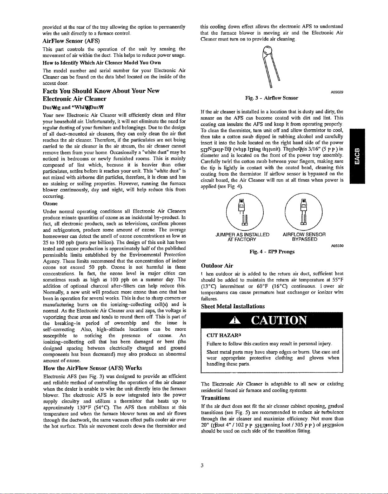
Hew the .'MrFlow Sensor (AFS) Works
Electronic AFS (see Fig 3) was designed to provide an efficient
and reliable method of controlling the operation of the air cleaner
when the dealer is unable to wire the unit directly into the furnace
blower. The electronic AFS is now integrated into the power
supply circuitry and utilizes a thermistor that heals up to
approximately 130°F (54_C). The AFS then stabilizes at this
temperature and when the furnace blower tams on and air flows
through the ductwork, the same vacuum effect pulls cooler air over
the hot surface. This air movement cools down the thermistor and
this cooling down effect allows the electronic AFS to understand
that the furnace blower is moving air and the Electronic Air
Cleaner must turn on to provide air cleaning
A05029
Fig. 3 - AJrflow Sensor
If the air cleaner is installed in a location that is dusty and dirty, the
sensor on the AFS can become coated with dirt and lint.. This
coating am insulate the AFS and keep it from operating properly
To clean the thermistor, tam unit off and allow thermistor to cool, 1
then take a cotton swab dipped in rubbing alcohol and carefully
insert it into the hole tocaled on the right hand side of the power
S[2dqt_sl-p E_ (whhn ll2_ing thHunit)ThHho_liS 3/I6" (5 p p ) in
diameter and is located on the front of the power tray assembly..
Carefully twirl the cotton swab between your fingers, making sore
the tip is lightly in contact with the coated bead, cleaning this
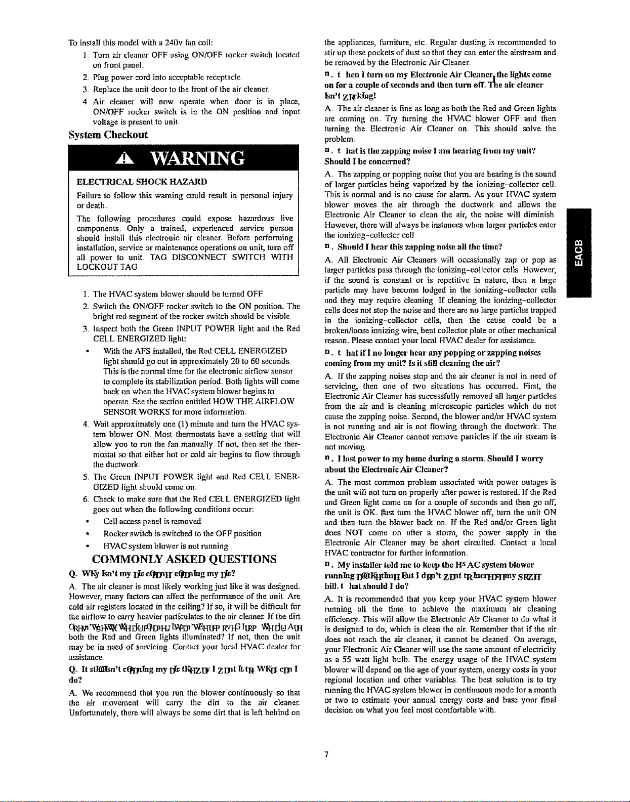
coating from the thermistor If airflow sensor is bypa_ed on the
circuit board, the Air Cleaner will run at all times when power is
applied (see Fig 4),
JUMPER AS INSTALLED
AT FACTORY
Fig. 4 - gP9 Prongs
AIRFLOW SENSOR
BYPASSED
AOSOaO
Outdoor Air
t hen outdoor air is added to the return air duct, sufficient heat
should be added to maintain the return air temperature at 55°F
(t3°C) intermittent or 60'_F (16"C) continuous lower air
temperatures can cause premature heat exchanger or ionizer wire
failures.
Sheet Metal Installations
CUT HAZARa
Failure to follow this caution may result in personal injury..
Sheet metal parts may have sharp edges or burrs. Use care and
wear appropriate protective clothing and gloves when
handling these pnrts.
The Electronic Air Cleaner is adaptable to all new or existing
residential forced air fumaca and cooling systums
qPransitions
If the air duct does not fit the air cleaner cabinet opening, gradual
transitions (see Fig. 5) are recommended to reduce air turbulence
through the air cleaner and maximize efficiency Not more than
20 ° ([_ut 4" / 102 p p SHJLanning loot / 305 p p ) o! FFSD_sion
should be used on each side of the transition fitting
/
Page 4

/
MAX 4"/102 mm DROP --
PER LINEAL 12"1305mm
AIR FLOW
2
AIR FLOW
CC3
"_"'_FURNACE
AIR
CLEANER
OPENING
ZZCZ
A_RCLEANER
TRANSITION SECTION
Fig. 5 - Transition to Unit
Turning Vanes
If the air cleaner is installed adjacent to a 90 ° duct elbow, add
turning vanes (see Fig. 6) inside the duct to improve air
distribution across the face of the air cleaner, Failure to follow this
recommendation can reduce the efficiency of the Electronic Air
Cleanet_
TURNIN G VANES
Fig, 6 - Turning Vanes
OPENING
FURNACE
A07sa?.
002038
Select Location for Air Cleaner
Remember to select a location that is readity access_le for periodic
inspection and cleaning of this air cleaner, Allow a minimum of
24" (610 ram) FtearanFe in IrRnt and 12" (305 ram) !_earanFe
above the air cleaner for component removal and service space
Planning the Installation
Application
Air cleaners are used in Iorced air heating cooling and ventilating
systems The air cleaner should be installed in the system so that all
the system air is circulated through the air cleaner The air cleaner
will only remove the airborne contaminants delivered to it,
Maximum performance is obtained when the system blower is set
for continuous operation
Installation Requirements
The best location for the air cleaner is in the return air duct next to
the blower compartment, In this location, the blower molor and
cooling coils will be kept clean.
UNIT OPERATION AND SAFETY HAZARD
Failure to follow this caution may result in reduced airflow
and potential operating problems
a o not install the air cleaner in the diseharge air duct
Before instaning the air cleaner, consider the application and type
of e VAC sy_em present, See Fig, 7 for the most common types, If
a transition between the ductwork and air cleaner is required, refer
to section entitled Transitions and Fig 5,, The unit must be readily
access_le for periodic inspection and cleaning of the prefilters and
electronic cells to maintain maximum efficiency and trouble-free
operation,
Air Conditioning
The air cleaner should be installed upstream of the cooling coil
This will keep the coil clean and reduce air conditioning coil
maintenance Improved cooling efficiency is the result and directly
affects energy costs A clean coil will reduce utility costs.
Humidifiers
An evaporative humidifier can be mounted upstream of the air
ctcanem, It is best to install an atomizing humidifier downstream of
the air cleaner because hard water salt deposiL_ and water droplets
may damage the air cleaner
UP_iL.OW F'_RN,K_
UPFLOW FURNACE UPFLOW FU_HAC_
_R FLGW
DO_FT_
/L98179
Fig. 7 - Typical Installations
4
Page 5

If an atomizing humidifier must be mounted upstream of this air
cleaner:
I Mount it as lar upmream as poss_le (recommended 6'/2m
minimum)
2 Install a standard di.cposable furnace filter between the
humidifier and the air cleaner to trap water droplets and
hard water salts
3 Clean the air cleaner more frequently to prevent a hard
water salt buildup
Direction of Airflow Through the Air Cleaner
This air cleaner is set up for left to right airflow when you are
facing the access door Cor right to left airflow, follow these
directions:
l, Oemove the prefilter(s) and cells from the cabinet., A plastic
positioning spacer is located inside the bottom of the
cabinet This spacer (see Cig 8) is secured to the cabinet
using a #6-32 round head rrhillips drive thread cutting
screw to assure installation of tile cells in the proper position
with respect to airflow.
20emove the screw and reposltion the spacer in the alternate
hole at the bottom of the cabinet
AOS2_S
Fig. 8 - Plastic Positioning Spacer
3. O eplace the screw to insure the plastic spacer is not
aceidentaIly knocked out of place during normal
maintenance It must be in.ailed in the hole provided
closest to the air leaving side of the cabinet. Peal the unused
hole with duct tape
4, Oemove the cell handle and reatlach to the opposite end of
the cell. Turn cells around, replace in cabinet and replace
prefiltars on the air entering side. The directional arrows on
the cel! end plates must point in the direction of airflow
INSTALLATION
This blectronic Air Cleaner _an be installed in any position, except
with the access door facing down Cig 7 shows examples of proper
air cieaner mounting with a variety of furnace installations
ELECTRICAL SHOCK HAZARD
eailure to follow this warning could result in personal injury
or death
The following procedures could expose hazardous live
components I nly a trained, experienced service person
should install this electronic air cleaner Before performing
installation, service or maintenance operations on uniL tam off
all power to unit TAd a IPCI NNbCr Pt 1TC e t IT e
il CKt rTTAd
ELECTRICAL SHOCK HAZARD
Cailure to follow this warning could r_'ult in personal injury
or death.,
The power mapply should be removed before installation To
remove the power supply, remove the two (2) screws in the top
front of the cabinet Oemember to keep this hardware for
reinstallation of the power supply when the air cleaner
installation is _mplete.
Prior to installing this product:
] Ocad rules and instructions carefully for safe operation
Cailure to follow them could damage the product or cause a
hazardous condition.
2 Check the ratings given on the product to make sure it is
suitable for your application.,
3 Pelect a location for the air cleaner,
40emove the old furnace filter and discard
5 The air cleaner cannot remove existing dirt from the blower
and ducts Clean the area thoroughly before you begin
60emove unit access panel, and slide the prefilters and
ionizing-collecting cells out of the cabinet, trlace them
safely aside for later use.
NOTE: The following is a typical installation of the air cleaner on
a upflow furnace, You may have to alter the installation to fit your
particular application,
Installation of the EAC
ELECTRICAL SHOCK HAZARD
Cailureto follow this warning could result in personal injury
ordeath,
The following procedures could expose hazardous live
components, t nIy a trained, experienced service person
should install this electronic air cleaner Before performing
installation, service or maintenance operations on unit, turn off
all power to unit TAd a tPCI NNbCT pt ITC e t ITe
il CKI rTTAd.
1. iocate the cabinet in the cold air return duct so that all of
the return air flows through the unit. If the furnace and air
cleaner openings are different, use a transition
2, Mounting holes are provided for ductwork attachment, The
,140" Koles (see) ig. 9) are sized lot #8 skeet metal screws,
Page 6

or1/8"rivets.Ifthe adjoining ductwork is flanged, install
the screws so that the screw heads are inside the cabinet
This will prevent damage to the prefiIters and optional
charcoal after-filler during removal and installation after
cleaning.
MOUNTtNG HOLES
AO7883
Fig. 9 - Mounting Hole Location
3. Alter tile unit has been secured I seat seams air tight with foil
tape or caulking
4. a etermlne direction of airflow and make any changes
necessary.
5, f_nstall prefilters and ionizer-collector ceils.
6. OeinstaIl power tray assembly into the cabinet
7., Oeinstat! unit access panet
ELECTRICAL INSTALLATION
Wiring Procedure
This air cleaner is powered by plugging the power cord into an
acceptable receptacle (see c [g, 1O)
W BL I g_[_tY_41_ff_S't-tf_t
3 5_ V,_ 5_Tran_e_
--- @
AO7Bt4
Fig., 10 - Typical Wiring Diagram
1.. Turn air cleaner I ec using I k ,q ec rocker switch located
on front panel.
2. Plug power cord into acceptable receptacle
3. o eplace the unit door to the front of the air cleaner
4. Air cleaner will now operate when door is in place I
I k/l cc rocker switch is in the I k position and inpuf
voltage is present to unit
Furnace Application
Acs will turn unit on when airflow is sensed. Air cleaner should
only operate when blower motor is running. The unit will also
operate normally if the air cleaner is hard wired directly to the
furnace control board To bypass the airflow sensor install the
jumper on the _9 prongs as shown in Cig 4 k ow theI air cleaner
will mn at all times when power is applied
UNIT DAMAGE HAZARD
Cailureto follow this caution may re_tt in damage to this
unit.
This unit cannot be powered directly from blower motor
leads Back Ej e (electromagnetic field) voltages can exceed
190 volts for 120v motors or possibly double with 240v fan
coil motors
ELECTRICAL SHOCK HAZARD
Cailure to follow this warning could result in personal injury
or death_
The following procedures could expose hazardous live
components, l nly a trained experienced service person
• . . L *
should install thls electrome air cleaner Before performing
installation service or maintenance operations on unit turn off
all power Its unit TAd a fSCl k kECT St fTC e! t iT e
i 1 Chl r TTAd..
The Electronic Air Cleaner is designed to take advantage of the
AcS (AirClow Sensor) into&water into the power supply. This
airflow sensor will sense the air movement within the duct and turn
the Electronic Air Cleaner on ,and off accordingly.
Fan Coil Application of 2020 Model (240v)
I ne j ode! 2020 is a 240v power supply model designed tu match
your fan coil Acs will turn unit on when airflow is sensed, Air
cleaner should only operate when blower motor is running,.
UNIT DAMAGE HAZARD
Caihre to follow this caution may result in damage to this
unit
This unit cannot be powered directly from blower meier
leads, Back Ej c (electromagnetic field) voltages can exceed
190 volts for 120v motors or poss_ty double with 240v fan
coil motors,
Page 7
To install this mode[ with a 240v tim cot!:
1 Turn air cleaner OFF using ON/OFF rocker switch ]o_ted
on front panel.
2 Plug power cord into acceptable receptacle
3 Replace the unit door to the front of the air cleaner
4 Air cleaner will now operate when door is in place,
ON/OFF rocker switch is in the ON position and input
voltage is present to unit
System Checkout
ELECTRICAL. SHOCK HAZARD
Failure to follow this warning could result in personal injury
or death.
The following procedures could expose hazardous live
components Only a trained, experienced service person
should install this electronic air cleaner. Before performing
installatlon, service or maintenance operations on unit, turn off
all power to unit. TAG DISCONNECT SWITCH WITH
LOCKOUT TAG.
l. "lqre HVAC system blower should be turned OFF
2. Switch the ON/OFF rocker switch to the ON position. The
bright red segment of the rocker ,.switch should be visible
3. Inspect both the Green INPUT POWER light and the Red
CELL ENERGIZED light:
• With the AFS installed, the Red CELL ENERGIZED
light should go out in approximately 20 to 60 seconds.
This is the normal time for the electronic airflow sensor
to complete its stabilization period Both lights will come
back on when the HVAC system blower begins to
operate.. See the section entitled HOW THE AIRFLOW
SENSOR WORKS for more information.
4. Wait approximately one (I) minute and turn the HVAC sys-
tem blower ON Most thermostats have a setting that wilt
allow you to run the fan manually If not, then set the ther-
mostat so that either hot or cold air begins to flow through
the ductworko
5. The Green INPUT POWER light and Red CELL ENER-
GIZED light should come on.
6 Check to make sure that the Red CELL ENERGIZED light
goes out when the following conditions occur:
" Cell access panel is removed
- Rocker switdl is switched to the OF F position
,' HVAC system blower is not running
COMMONLY ASKED QUESTIONS
Qo WKy Isn't my Bl_ cqtDaH` cQEnlag my Blv?
A. The air cleaner is most likely working just like it was designed.
However, many factors can affect the performance of the unit_ Are
cold alr registers located in the ceiling? If so, it will be difficult for
the airflow to carry heavier particulates to the air cleaner If the dirt
chrw'v_r/,_'_lorqtoaru_:t_'_rarp _tt_ _OoAm
both the Red and Green lights illuminated? If not, then the unit
may be in need of servicing. Contact your local HVAC dealer for
asslstance_
Qo It s_n't eqtDalng my I_ tKHZI_ I zUnt It,tit WIrq3teEn I
do?
A. We recommend that you run the blower continuously so that
the air movement will carry the dirt to the air cle,'mer.
Unfortunately, there will _flways be some dirt that is left behind on
the appliances, furniture, etc Regular dusting is recommended to
stir up these pockets of dust so that they can enter the alrstrcam and
be removed by the Electronic Air Cleaner
n ,, t hen I turn on my Eh:ctronic Air Cleanerlthe lights come
on for a couple of seconds and then turn off., The air cleaner
Isn't zRrklng!
A The air cleaner is fine as long as both the Red and Green lights
are coming on. Try turning the HVAC blower OFF and then
turning the Electronic Air Cleaner on This should solve the
problem.
n t hat is rite zapping noise I am hearing from my unit?
Should I be concerned?
A. The zapping or popping noise that you are hearing is the sound
of larger particles being vaporized by the ionizing-collector cell.
This is normal and is no cause for alarm.. As your HVAC system
blower moves the air through the dnctwork and allows the
Electronic Air Cleaner to clean the air, the noise will diminish
However, there will always be instancea when larger particles enter
the ionizing-collector cell
n Should I hear thL_ zapping noise all the time?
A._ All Electronic Air Cleaners will occasionally zap or pop as
larger particles pass through the ionizing-collector cells. However,
if the sound is constant or is repetitive in nature, then a large
particle may have become lodged in the ionizing-collector cells
and they may require cleaning If cleaning the ionizing-collector
cells does not stop the noise and there are no large particles trapped
in the ionizing-collector cells, then the cause could be a
bruken!toose ionizing wire, bent collector plate or other mechanica!
reason. Please contact your local HVAC dealer for a._sistance..
n o t hat if I no longer' hear any popping or zapping noises
coming from my unit? Is it still denning the air"?
A. If the zapping noises stop and the air cleaner is not in need of
servicing, then one of two situations has occurred.. Flint, the
Electronic Air Cleaner has successfully removed all larger particles
from the air and is cleaning microscopic particles which do not
cause the zapping noise Second, the blower and/or HVAC system
is not running and air is not flowing through the ductwork. The
Electronic Air Cleaner cannot remove particles if the air stream is
not moving.
n. I lost power to my home during a storm,, Should I worry
about the Electronic Air Cleaner'?
A. The most common problem associated with power outages is
the unit will not turn on properly after power is restored. If the Red
and Green light come on for a couple of seconds and then go off,
the unit is OK gust turn the HVAC blower off, turn the unit ON
and then turn the blower back on If the Red and/or Green light
does NOT come on after a storm, the power supply in the
Electronic Air Cleaner may be short circuited. Contact a local
HVAC contractor for further information_
n. My installer told me to keep the H s AC system blower
running _KHtlmH l_t I dRn't Z13at tRlncrHyHmy SIGH"
bill, t hatshould I do?
A.. It is recommended that you keep your HVAC sy_em blower
running all the time to achieve the maximum air cleaning
efficiency. This will allow the Electronic Air Cleaner to do what it
is designed to do, which is clean the air. Remember that if the air
does not reach the air cleaner, it cannot be cleaned On average,
your Electronic Air Cleaner will use the same amount of electricity
as a 55 watt light bulb. The energy usage of the HVAC system
blower will depend on the age of your system, energy costs in your
regional location and other variables The best solution is to try
running the HVAC system blower in continuous mode for a month
or two to estimate your annual energy costs and base your final
decision on what you fee! most comfortable with.
Page 8

Remove
Soak
Rinse
Fig_ 11 - "l_pieal Call and Prefiller Cleaning
Drip Dry
Replace
CO203S
I
MAINTENANCE OF CELLS
Washing Ceils and Prefilters
Regular washing is necessary to ensure proper performance (see
Fig 11). A thorough washing once every two months wilt be
adequate for most installations More frequent washing (once a
month) may be nece_ary on some installations (new homes for
example) where there is new carpeting, plaster dust, or excessive
cigarette smoke
To remove cells and prefilter
1. Push air cleaner switch to the OFF position Wait 15
seconds. Open door access panel.
2. Carefully remove cells and prefilter(s) and set aside in a safe
place,
3 Do not drop the ionizing-collector cell This could cause
damage to the cell plates or ionizing wires and cause
excessive arcing and noise,
To wash cells and prefilter(s)
To wash cells and prefilter(s) We suggest that you follow the
instructions below to properly and thoroughly clean your collector
cells
i Place enough hot water in a utility tub to cover the first ceil.
Dissolve 2 to 4 oz of granulated automatic dishwasher
detergent (not laundry detergent) in the water.
2 Allow the cell to soak for 30 minutes Agitate it up and
down in the solution until it appears clean and remove
3 Repeat with second cell.
4 Agitate the prefitters up and down in the solution until they
appear clean.
5 With a hose, rinse the cells and prefilters The hose should
be heCI I'_RU\M0 " (254 pp) fzRp _ FetiDp(_ El_d IJAiD
slight angle for better cleaning results Be careful not to
spray the ionizing wires directly with the hose The water
pressure can cause the wire to snap and break, The ceil
frame should be thoroughly rinsed along the edges to
dislodge any trapped lint or dirt. Carefully wipe a damp
cloth or .sandpaper (not emery cloth) along the ionizing
wires,,
6 Ptand cells and prefilters up to drain. [_t dry two hours
You may experience a slight discoloration of the aluminum
collector cells after washing This is a normal chemical
reaction and will not harm your unit or affect its
performance.
To replace cells in air cleaner
I. Replace prefilter and cells in cabinet.. Cheek that arrow on
cells poinLs in same direction as air flows through the duct
(ff you have to force it past the positioning screw on
bottom, it is probably in the wrong position).
2.. Replace access door (engage tabs on lower edge of door
into slots in cabinet) Carefully close door_
3. Turn air cleaner switch to ON
TROUBLESHOOTING
ELECTR1 CAL SHOCK HAZARD
Failure to follow this warning could result in persona[ injury
or death.
The following procedures could expose hazardous live
components Only a trained, experienced service person
should install this electronic air cleaner When the circuit has
been de-energized, always discharge any residual current in
the secondary with an insulated handle screwdriver Always
ground power supply and ionlzing-coltecting cell when bench
testing. Before performing installation, service or maintenance
operations on unit, turn off all power to unit TAd
DfPCONNbCT PWfl'C e WITe LOCh O r T TAd.
Recommended Service Tools
1.. 6FrewdrLy_r, 8" FRP P Rn wLW IasuO.j_iJ hDldO (,p(?t_x_)
2. Pcrewdrivers Phillips #1 and #2 with plastic insulated
handles
3, Needle nose pliers
4 Multimeter
5. e igh voltage probe
Indication of Electrical Trouble
The air cleaner is equipped with a Red CbLL bNbRd fWbD light
for indicating proper unit operation. When the unit is in normal
operation (with the e s AC system fan running, access door in place
and rocker switch in the ON position) and the Red CbLL
bNbRdfWbD light is not lit, the problem is a shorled secondary.
Although failure of the indicating light itself should not be
overlooked, this condition is unusua| and rather remote.
Primary Circuit with Blower Operating
ff there is supply line voltage at the connections and no input
voltage to the power supply, the outage can be located by checking
operation of the safety switch and the interconnecting wiring with a
multimeter Refer to Circuit Diagram, to check operation of the
switches. Following these steps to test for proper operation of the
circuit board and power supply assembly:
1 bnsure that the circuit breaker controlling the furnace
blower is in the ON position and the main fuse is not open.
2 The power supply board has a built-in internal fuse to
protect the 24 s transformer ft can be checked visually by
inspecting the fuse ff the fine wire inside the fuse is broken,
this indicates a problem in the 24s circuit of the power
supply board.. Do NOT replace this fuse The entire power
supply board must be replaced The purpose of the fuse is
not to protect the power supply board, but to function as a
troubleshooting feature of the product and to protect the
transformer from damage
Page 9

3. If the fuse is NOT blown, check the ON/OFF _vitches and
safety interlock witch for proper engagement and
operation This can be completed using a volt ohm
millimeter on a scale that will measure ohms as low as 1 0
If you are using the recommended meter previously
mentioned in this manual, set the meter to read 200 ohm
and proceed with Steps 4 through 6
4 Remove the fuse Connect one lead to the test pin located
direclly beside the wire that connects the ON/OFF switch to
the power supply board Connect the other lead to the fuse
connection closest to the front panel,
5 Turn the ON/OFF switch to the ON position and depress
the safety interlock switch The meter should have the
capability of reading levels as low as I 0 ohm
6 If there is no reading on the meter, begin the process of
elimination by disconnecting the wire from the test point
and connecting it to the terminal with the blue wire located
on the safety interlock .switch. Depress the safety interlock
switch lfthe reading on the meter is greater than ] 0 ohm,
the safety interlock switch is defective and must be replaced.
If the reading on the meter is less than t 0 ohm, the
ON/OFF switch is defective and must be replaced.
Ionizing-Collecting Cell
Secondary Circuit
The cell is electrically energized through a contact terminal located
at the top center of the cell. The ionizing wires and alternating
collector plates are electrically charged while the interleaving plates
are grounded If the space between the charged and grounded
plates is bridged with conductive or semi-conductive materiaI, a
short circuit develops The bridging or short may be caused by
damaged plates, or foreign material lodged between/on the
components.
Since the cell should be periodically removed from the unit to
wash away collected dirt, it is s'uscept_le to physical damage. The
cell also contains the ionizing wires which, due to their function,
have been designed with minimal structural support and are
suscept_le to breakage. However, trouble related to a shorted
collector cell is readily shown by the Red CELL ENERGIZED
light and can be quickly isolated by a simple procedure.
To determine if a short exists in one or both of the collector cells,
tam the Electronic Air Cleaner OFF and remove both electronic
cells from the cabinet. Shut the door and repower the unit. If the
Red CELL ENERGIZED light comes on, an electrical short exists
in one or both of the electronic cells. Replace the cells in the unit,
one at a time, to determine which ceil is shorted Most troubles in
the colt can be visually detected and corrected.
NOTE: The ionizer collector cells ,are not designed for field repair.
Ionizing wires ,and insulators can be field replaced It is not
recommended that you attempt to replace other cell components
(i e Collector plates, end plates, ionizer supports)
Replacing the Ionizing Wires
Ionizing wire breakage is minimal because of the constant tension
design and fixed location of the ionizing wire supports. When an
ionizing wire breaks, the efficiency of the Electronic Air Cleaner
will decrease slightly. However, the unit will continue to operate
with broken ionizing wires as long as the broken wires have not
caused a short circuit of the unit Remove all loose and broken
wires as soon as they are identified. Although the replacement of
the ionizing wires can be attempted by a homeowner, it is
recommend that you should contact a qualified HVAC contractor
for replacement parts and/or servicing.
Wires are supplied in a coiled spring configuration, with a clinch
nut on each end of the wire Replacement requires a pair of needle
nose pliers Exercise caution in removing any broken wires in the
collector cell.. This will prevent accidental shorting of the cell and
reduce the need for further maintenance U_ the following
procedure when replacing an ionizing wire
I. Ensure that alt power to the Electronic Air Cleaner is OFF,
remove the access door and remove the ionizing-collector
cells from the uniL
2 Carefully remove a!l remains of the broken wire
3 Grip the neW wire at each end of the wire with your thumb
and index finger While stretching the wire to approximately
6" (152 ram) _ RnH_GRI kh_Hzl_lq'_l_ UnFRIDEH_FFP
your thumb and index finger.
4 n'laca one end of the wire in the slot of the stainless steel
.support on the collector cell fi'om the front of the cell This
_pport is partially covered by the cell brace in front of the
support
5.. Grip the other end of the ionizing wire with needle nose
pliers and insert the terminated end of the wire into the slot
on the support bar of the opposite end of the collector cell
6. The wire should be tight enough to be self supporting and
remain suspended between the two support slots in the
_pport bar.
ELEfYI"RICAL SHOCK HAZARD
Failure to follow this warning could result in personal injury
or death
]'he following procedures could expose hazardous five
components. Only a trained, experienced service person
should install this electronic air cleaner Before performing
installation, service or maintenance operations on unit, turn off
all power to unit TAG DISCONNECT SWITCH WITH
LOCh OUT TAG.
AFS Troubleshooting
1. Make sure the furnace blower is not operting, the rocker
_,viteh is OFF, and the circuit breaker is turned OFF or the
cord is disconnected
2.. Remove the access door
3. Remover power tray assembly
4.. Locate the AFS It is the circuit board with a small gray disc
connected to the circuit board by two (2) silver wires.
Carfutly bend the thermistor so that it is located in the center
RI WHt_t_Iag _G i$S1Rxlml:_-_) I/8" (3 ram) tlRm WH
inside edge of the power pack assembly
5.. Reinstall the power tray assembly and access door
High Altitude Operation
Because the air is Iess dense at higher altitudes, there is a poss_ility
of nuisance arcing The homeowner can quickly and easily correct
this condition..
]. Turn the unit OFF Turn off circuit breaker or disconnect the
power cord
2_ Remove the two screws that secure the cover to the power
tray and remove it from the unit (The entire power supply
tray may be removed from the cabinet by removing two
screws from inside cabinet.) Do not lose these ,screws
I
Page 10

3,, k_cate the jumper terminal (see 12)_ wire support bar with end of the high voltage probe, The
meter reading should be 62 kVDC - 2 kVDC
ELECTRICAL SHOCK HAZARD
Cailure to follow this warning could result in personal injury
or death
The following procedures could expose hazardous live
components Only a trained, experienced service person
should install this electronic air cleaner. Before performing
O0203g
Fig. 12 - Jumper Terminal Adjuslment
installation, service or maintenance operations on unit, turn off
all power to unit TAG DISCONNECT SWITCH WITH
LOCh O r T TAG
4, With a pair of needle nose pliers, carfia!ly adjust the jumper
settings from HIGH to MED Ensure that the jumper is
firmly seated in the terminal.
5 Replace the power tray cover and secure it with the two
SCrews
6.. Replace the access door and turn the unit ON.
This procedure will slightly reduce the output voltage, minimize
aming, and reduce ozone production.. If the condition does not
improve, repeat the above procedure and move the jumper setting
from MED to L.OW If this does not correct the situation, contact
your local HVAC dealer All Electronic Air Cleanem are produced
at the factory with the jumpers set in the HIGH position However,
the output voltage may be lowered in any situation where the unit
is arcing excessively or there is excessive ozone production..
Checking the Power Supply
If the output light remains out with the collector cells removed
from the cabinet, the power supply is defective. Specific problems
on the power tray assembly can be isolated by using a multimeter
and high voltage probe to check the output voltages. To check the
secondary circuit, a high voltage meter is required.. See the section
entitled Recommended Service Tools To check for proper
operation, it is imperative that the procedure be followed as
outlined below:
L Make sure the furnace blower is operating, the control
switch is on, and input voltage is correct..
2. Remove front door assembly panel
3.. Remove power pack access cover
4.. Check tile high voltage contact board assembly(s) for
damage or carbon tracking.
NOTE: The cell contacts should be visually checked for
corrosion, excessive dirt build up, and electrical are tracking
(carbon path from stainless steel spring to grounded metal) Clean
or replace as required.
5.. Make connections from the high voltage probe to the
mu(tM_14lq" In IyocRrGD_cHwl3/€ WH RS_'VmDml;9 ThH
meter should be set for reading DC voltage on the 20 volt
full scale
6.. Attach the high voltage probe ground lead to the cabinet.
While depressing the safety switch lever, touch the ionizer
Z tf no voltage is measured, remove the first cell ,'rod check
the second cell The meter should read 6.2 kVDC - .2
kVDC
8. If proper voltage is measured, the first cell is shorted
9. If no voltage is present, remove the second cell Ins-tall cell
number one and me,_sure voltage as described above. If
voltage is present, the second cell, which is now out of the
cabinet, is shorted
I0. If no voltage is present, remove both cells and measure the
power supply output. Wlaile drpressing the safety switch,
touch the end of the high voltage probe (see Cig 13) to
either the front or rear contact board assembly The meter
should read 62 kVDC or higher
11 If no voltage is present, check the power supply.. Set the
multimeter for reading AC voltage at 200 volt full scale and
attach meter test leads
12 While depressing the safety lever, touch the two transformer
output lead junctions to the power supply board with the
meter leads and read the meter.
13 If there is no oputput voltage from 24 volt transformer,
replace the 24 volt tranformer and power apply board
J
A_717_
Fig_ 13 - High Voltage Operation Check
(Ionizer Wire Support Bar)
10
Page 11

\
PARTS LIST
-CELL
CONTACT
J
Reference Number
1
2
3
4
5
6
7
8
9
10
tl
12 (120v model)
12 (240v model)
13
14
15
CO4D05
PARTS LIST
Description
Power Tray Assembly
High Frequency Power Supply
ON/OFF Switch
interlock Switch
Cabinet Assembly
Prefilter (2 required)
Celt, Ionizing - Collecting
Ionizing Wire Assembly
Front Penet Assembly
Contact Board Assembly (2 required)
Charcoal Filter (optional, not shown)
Stepdown Transformer t20v to 24v
Stepdown Transformer 240v to 24v
Insulator
Cell Key (not shown)
Power Tray Cover
Fig. 14 - Unit Parts l)c,scripfien
Page 12

"t:, = _
°° i
%
_NN
_ m
z
m
)
o
b.
]2
m
Page 13

CAC / BDP
FOR SERVICE OR REPAIR, FOLLOW THESE STEPS IN ORDER:
FIRST: Contact the Installer You may find their name on the product or in your Homeowner's Packet ifthe installer's name is not known cell your
builder or home reta';_erif yours isa new residence
SECOND: Contact the nearest dist_butor (See telephone yellow pages )
THIRD: Contact:
CAC 1BDP
Consumer Relations
P O Box 4808
Syracuse, New Ye_'k 13221
Phone: 1-800-227_7437
Mode No Unit Sedal No
Date ofInstallation Installed by
Name of Owner Address of _nstallation
EAC- Limited Warranty
FIVE-YEAR LIMITED WARRANTY-- CAC t BOP (hereinafter also interred to as "COMPANY') warrants this cabinet/product to be free from defects in
matada] and workmanship If a defect is found v_thin five years from date of original installation of product (whether or not actua! use begins on that
date) Company will provide a new or remanufa_ured part. at Company's sole oplJon_ to replace any defec_Jve part, without charge for the pad ilseft
THIS WARRANTY DOES NOT INCLUDE LABOR OR OTHER COSTS incurred for diagnosing, repairing, remo,c;ng, installing, shipping, servlcing_ or
handling of either defective parts or mpIacement pads
WARRANTY CONDITIONS:
1_ Warranties apply only te profilers in their original testel]etion location,
2., Instagetion, use, care, and maintenance must be norto!! and in accordance with instructions coet,_ined in the Owner's Manual
and Company's service Infonoatian..
3., D_f_ctivepartemust_erotumedt_thedist_butorthr_ugharog_steredserv_ctegdea_rf_rcrsdiL
4., All work shall be performed during normal working hours,
LIMITATIONS OF WARRANTIES - ALL IMPLIED WARRANTIES {INCLUDING IMPLIED WARRANTIES OF MERCHANTABILITY AND FITNESS
FOR A PARTICULAR PURPOSE) ARE HEREBY UMITED IN DURATION TO THE PERIOD FOR WHICH THE LIMITED WARRANTY tS GIVEN AND
_PL!ES_,,SOME,STATES, DO,NO T ALLOW,LIM!TATIONS,ON HOW LONG,AN,IMPLIED WARRANTY LASTSt SO THE ABOVE MAY NOT APPLY
TO YOU. THE EXPRESSED WARRANTIES MADE IN THIS WARRANTY ARE EXCLUSIVE AND MAY NOT BE ALTERED 1ENLARGED OR
CHANGED BY ANY D_STRIBUTOR, DEALER, OR OTHER PERSON WHATSOI::_VER,
COMPANY WILL NOT BE RESPONSIBLE FOR:
't., Normal maintenance as outlined in the installation and servicing instructions or owner's manual, including filter cleaning andlor
replacement and lubricatlon_
2 Damage_rro_a_rsroquirodasac_nsequ_nce_ffau_tyi_stat_otion`misappIicati_n_b_mpr_p_rservicing_una_th_dzed
alteration or improper oporstton_
3 Failure to start due to voltage conditions, blown fuses, open circuit breakers, or damages due to the inadequacy or Interruption
of electrical service,,
4. Damage as a result of floods, winds, fires, lightning, accidente, corrosive envtronmenLs or other conditions beyond the control
of Company.,
5_ Pad_ not supplied or designated by Company, or damages resulting from their uso_
6_ Company products installed outside the continental U S,A_, Aiaska, Hawaii, and Canada,,
7_ E_ectri_ityorthe_c_sts_ori_crs_se_ineIectricity_rfue_c_tafr_manyreas_nwh_tsoever_nc_udingadd_at_r_nusua_s_
of supplemental electric heal
8., ANY SPECIAL INDIRECT OR CONSEQUENTIAL PROPERTY OR COMMERCIAL DAMAGE OF ANY NATURE WHATSOEVER.
Some states do not allow the exclusion of incidental or consequential damages, so the above limitation may not appfy to you,
Catalog 63EA-CA0
05-03
This warranty gives you specific legal rights, and you may also have other fights which vary from state to state
39004DP290
t3
Page 14

Copyright 2007 CAC / BDP • 73_0 W, Morris SL • Indianapolis= IN 4_31 prir_ in Cl-_rt_ EdiUon D_t0:09/07
i i
Matt_lac_ur_' rm_erves tho right 1och_ng_ at _ny Ume_ Bp{tclflc=tlon_; at_dd _sEgn= wit hour noUco and wit haut ob[ig=Uo_=,
Catalog No: IM-EACB-03
Replaces:tM-EACB-02
 Loading...