

Page 1
CRECOMZR076A00
CRECOMZR078A00
CRECOMZR080A00
Installation Instructions
Read these instructions completely before attempting to install the
Vertical EconoMi$er X Accessory.
CONTENTS
SAFETY CONSIDERATIONS . . . . . . . . . . . . . .1
GENERAL. . . . . . . . . . . . . . . . . . . . . . . . . . . . . .1
EconoMi$er X Sensor Usage . . . . . . . . . . . . . 2
ACCESSORIES LIST. . . . . . . . . . . . . . . . . . . . .2
WIRING DIAGRAMS. . . . . . . . . . . . . . . . . . .5-7
INSTALLATION . . . . . . . . . . . . . . . . . . . . . . . .2-8
EconoMi$er X Standard Sensors . . . . . . . . . .8
EconoMi$er X Control Modes . . . . . . . . . .8-14
OPERATION . . . . . . . . . . . . . . . . . . . . . . . . . . .16
TROUBLESHOOTING . . . . . . . . . . . . . . . . . . .17
SAFETY CONSIDERATIONS
Improper installation, adjustment, alteration, service, maintenance, or
use can cause explosion, re, electrical shock or other conditions which
may cause personal injury or property damage. Consult a qualied
installer, service agency, or your distributor or branch for information
or assistance. The qualied installer or agency must use factoryauthorized kits or accessories when modifying this product. Refer to
the individual instructions packaged with the kits or accessories when
installing.
Follow all safety codes. Wear safety glasses and work gloves. Use
quenching cloths for brazing operations and have a re extinguisher
available. Read these instructions thoroughly and follow all warnings
or cautions attached to the unit. Consult local building codes and
appropriate national electrical codes (in USE, ANSI/NFPA70,
National Electrical Code (NEC); in Canada, CSA C22.1) for special
requirements.
It is important to recognize safety information. This is the safety-alert
symbol . When you see this symbol on the unit and in instructions
or manuals, be alert to the potential for personal injury.
Understand the signal words DANGER, WARNING, CAUTION, and
NOTE. These words are used with the safety-alert symbol.
DANGER identies the most serious hazards which will result in
severe personal injury or death. WARNING signies hazards which
could result in personal injury or death. CAUTION is used to identify
unsafe practices, which may result in minor personal injury or product
and property damage.
NOTE is used to highlight suggestions which will result in enhanced
installation, reliability, or operation.
ELECTRICAL SHOCK HAZARD
Failure to follow this warning could cause personal injury or death. Before performing
service or maintenance operations on the unit, always turn off main power switch to
unit and install lock(s) and lockout tag(s). Unit may have more than one power switch.
Ensure electrical service to rooftop unit agrees with voltage an amperage listed on the
unit rating plate.
!
WARNING
!
Small Rooftop Products
Select 3 to 12 1/2 Tons
Vertical EconoMi$er X Accessory
CAUTION
!
CUT HAZARD
Failure to follow this caution may result in personal injury.
Sheet metal parts may have sharp edges or burrs. Use care and wear appropriate
protective clothing, safety glasses and gloves when handling parts and servicing
roof top units.
GENERAL
IMPORTANT: These economizers meet the economizer requirements
as laid out in California’s Title 24 mandatory section 120.2 (fault
detection and diagnostics).
The EconoMi$er X system utilizes the latest technology available
for integrating the use of free cooling with mechanical cooling for
packaged rooftop units. The solid-state control system optimizes energy
consumption, zone comfort, and equipment cycling by operating the
compressors when the outdoor-air temperature is too warm, integrating
the compressor with outdoor air when free cooling is available, and
locking out the compressor when outdoor-air temperature is too cold.
Demand control ventilation is supported.
This EconoMi$er X can be used with 1, 2, or 3 speed (48/50LC 07-12)
units.
The EconoMi$er X system utilizes gear-drive technology with a directmount spring return actuator that will close upon loss of power. The
EconoMi$er X system comes standard with an outdoor air temperature
sensor, mixed air temperature sensor. Outdoor enthalpy, indoor
enthalpy, indoor temperature, and CO2 sensors are available for eld
installation. See Table 3 for sensor usage.
Standard barometric relief dampers provide natural building
pressurization control. An optional power exhaust system is available
for applications requiring even greater exhaust capabilities. The power
exhaust set point is adjustable at the EconoMi$er X controller.
See Table 1 for package usage. See Table 2 for package contents. See
Table 3 for sensor usage.
Table 1 - Package Usage
UNIT SIZE PART NUMBER
Small Cabinet, Footprint size: 46 3/4” x 74 3/8” CRECOMZR076A00
Large Cabinet, Footprint size: 58 1/2” x 88 1/8” CRECOMZR078A00
Extra-Large Cabinet, Footprint size: 63 3/8” x 115 7/8” CRECOMZR080A00
Table 2 - Package Contents
PACKAGE NO. QTY CONTENTS
1
Hood Top and Sides
1
Hood Divider
1
Aluminum Filter
CRECOMZR076A00,
CRECOMZR078A00
CRECOMZR080A00
18
Screws
1
EconoMi$er X Assembly
1
HH79ZZ007 Mixed (supply)
Temperature Sensor
1
48TMHSRSE--A20 Harness
1
Hood Top and Sides
1
Hood Divider
1
Hood Filter Divider
2
Aluminum Filters
1
Hardware Bag
1
EconoMi$er X Assembly
1
HH79ZZ007 Mixed (supply)
Temperature Sensor
1
48TMHSRSE--A20 Harness
1
Page 2
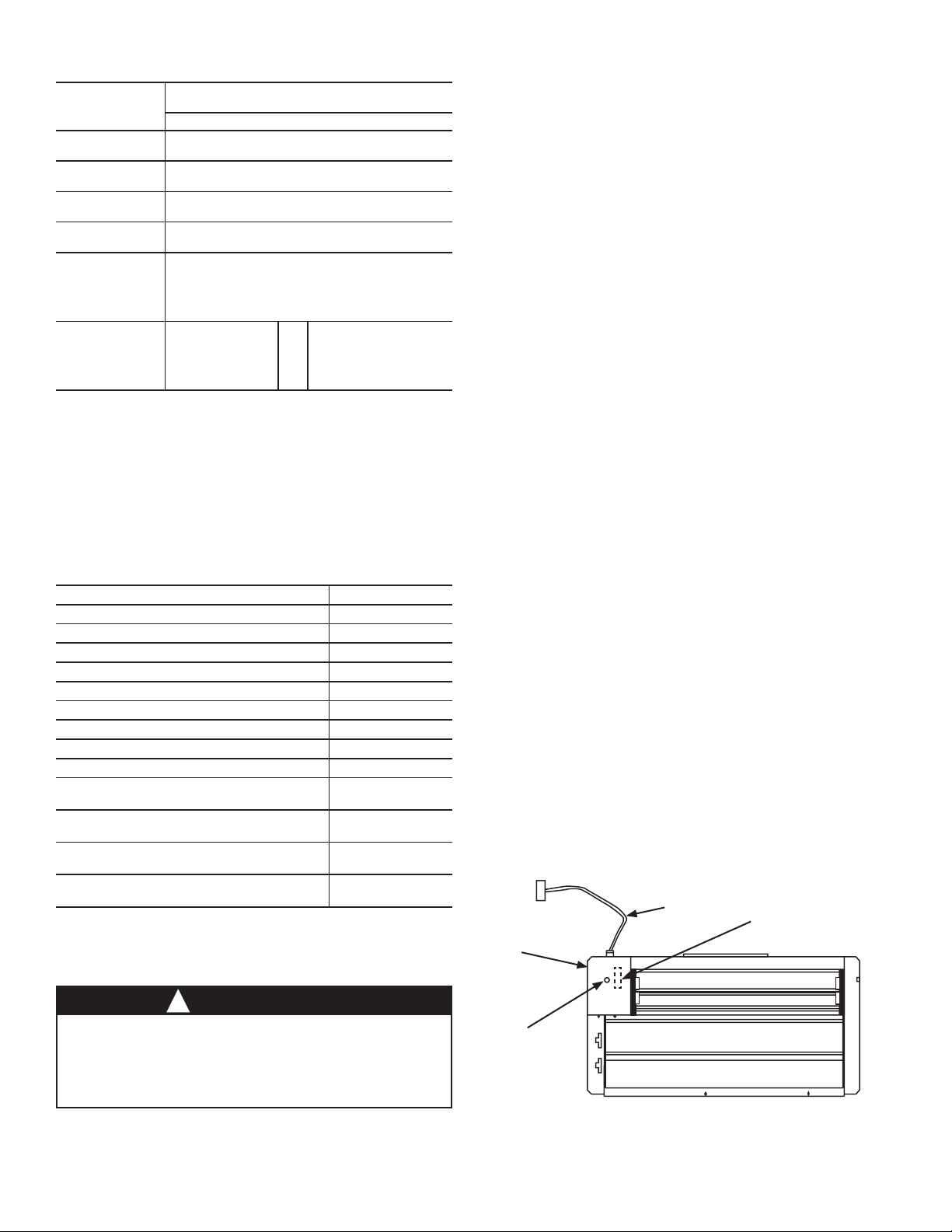
Table 3 - EconoMi$er X Sensor Usage
ECONOMI$ER X WITH OUTDOOR AIR
APPLICATION
Outdoor Air
Dry Bulb
Mixed Air
Sensor
Single
Enthalpy
Differential
Enthalpy
CO2 for
DCV Control
Using a
Wall-Mounted
CO2 Sensor
CO2 for
DCV Control
Using a
Duct-Mounted
CO2 Sensor
†33ZCSENCO2 and CGCDXSEN004A00 are accessory CO2 sensors.
**33ZCASPCO2 and CGCDXASP00100 are accessory aspirator boxes required for ductmounted applications.
††CRCBDIOX005A00 is an accessory that contains both 33ZCSENCO2 and 33ZCASPCO2
accessories.
HH79ZZ007 is factory installed on economizer
HH79ZZ007 provided with economizer and eld installed
33ZCSENCO2 or
CGCDXSEN004A00†
33ZCASPCO2 or
CGCDXASP00100**
DRY BULB SENSOR
Accessories Required
in blower compartment
33ZCSENCO2
CGCDXSEN004A00
and
HH57AC081
HH57AC081
or
OR
CRCBDIOX005A00††
ACCESSORIES LIST
The EconoMi$er X has several eld-installed accessories available to
optimize performance. Refer to Table 4 for authorized parts and power
exhaust descriptions
Table 4 - EconoMi$er X Field-Installed
Accessories
DESCRIPTION PART NUMBER
Small Cabinet Power Exhaust 208-230 v 1 Ph CRPWREXH030A01
Small Cabinet Power Exhaust 460 v 3Ph CRPWREXH021A01
Large Cabinet Power Exhaust 208-230 v 1 Ph CRPWREXH022A01
Large Cabinet Power Exhaust 460 v 3 Ph CRPWREXH023A01
Extra Large Cabinet Power Exhaust 208-230 v 1 Ph CRPWREXH080A00
Extra Large Cabinet Power Exhaust 460 v 3 Ph CRPWREXH081A00
Outdoor Air Enthalpy Sensor HH57AC081
Indoor Air Enthalpy Sensor HH57AC081
Return Air CO2 Sensor (4 to 20 mA) CRCBDIOX005A00
CO2 Room Sensor (4 to 20 mA)
Aspirator Box for Duct Mount
CO2 Sensor (4 to 20 mA)
Space Temperature and CO2 Room Sensor
with Override (4 to 20 mA)
Space Temperature and CO2 Room Sensor
with Override and Set Point (4 to 20 mA)
33ZCSENCO2 or
CGCDXSEN004A00
33ZCASPCO2 or
CGCDXASP001A00
33ZCT55CO2
33ZCT56CO2
INSTALLATION
1. Turn off unit power supply(s) and install lockout tag.
2. Remove the existing unit lter access panel. Raise the panel and
swing the bottom outward. The panel is now disengaged from the
track and can be removed. (See Fig. 2.)
3. Remove the indoor coil access panel and discard. (See Fig. 2.)
4. The EconoMi$er X hood components are shipped with the
EconoMi$er X. Remove hood from packaging. The hood top and
sides are shipped factory assembled.
NOTE: If the power exhaust accessory is to be installed on the unit,
the hood shipped with the EconoMi$er X will not be used and may be
discarded. Save the aluminum lter for use in the power exhaust hood
assembly.
5. Insert the hood divider between the hood sides. (See Fig. 3) Secure
hood divider with 2 screws (provided) on each hood side. Screws
should go through the hood sides into the divider. The hood divider
is also used as the bottom lter rack for the aluminum lter. On
hood for extra large cabinet install lter divider. (See Fig. 4A.)
6. Set the EconoMi$er X upright. (See Fig. 5.)
7. Slide the EconoMi$er X assembly into the rooftop unit. (See
Fig. 5). On small and large cabinets be sure to engage the rear
EconoMi$er X ange under the tabs in the return-air opening of
the unit base. (See Fig. 6)
8. Secure the EconoMi$er X to unit along side and bottom anges
using the screws provided.
9. Remove the tape securing the relief dampers in place.
10. Remove and save the 12-pin jumper plug from the unit wiring
harness (located in the upper left corner of the unit). Insert the
EconoMi$er X plug into the unit wiring harness. Refer to Fig. 7
and 8 for wiring details.
NOTE: The 12-pin jumper plug should be saved for future use, in the
event that the EconoMi$er X is removed from the unit. The jumper plug
is not needed as long as the EconoMi$er X is installed.
11. If EconoMi$er X will be operating under enthalpy control, replace
the factory installed HH79ZZ007 outdoor dry bulb temperature
sensor with accessory enthalpy sensor HH57AC081. (See Fig. 1.)
12. Remove the indoor fan motor access panel. (See Fig. 9.)
13. The mixed (or supply) air temperature sensor looks like an eyelet
terminal with wires running to it. The sensor is located on the
“crimp end” and is sealed from moisture. Locate the sensor in
the economizer hardware bag. Mount the supply air temperature
sensor (provided) to the lower left section of the indoor fan blower
housing. (See Fig. 10.) Use the screw provided and use existing
hole. Locate the orange and brown wires in wire bundle in the
indoor fan section. Connect the orange and brown wires to the
corresponding connections on the supply air temperature sensor.
(See Fig. 8.)
Wiring
Harness
Actuator
(Hidden)
HH57AC081
Enthalpy Accessory
Location (Field
Installed)
WARNING
!
ELECTRICAL SHOCK HAZARD
Failure to follow this warning could result in personal injury and/
or death.
Disconnect power supply and install lockout tag before attempting
to install accessory.
HH79ZZ007
Outside Air
Temperature
Sensor
Fig. 1 - EconoMi$er X Component Locations —
(Small Cabinet Economizer Shown)
2
Page 3
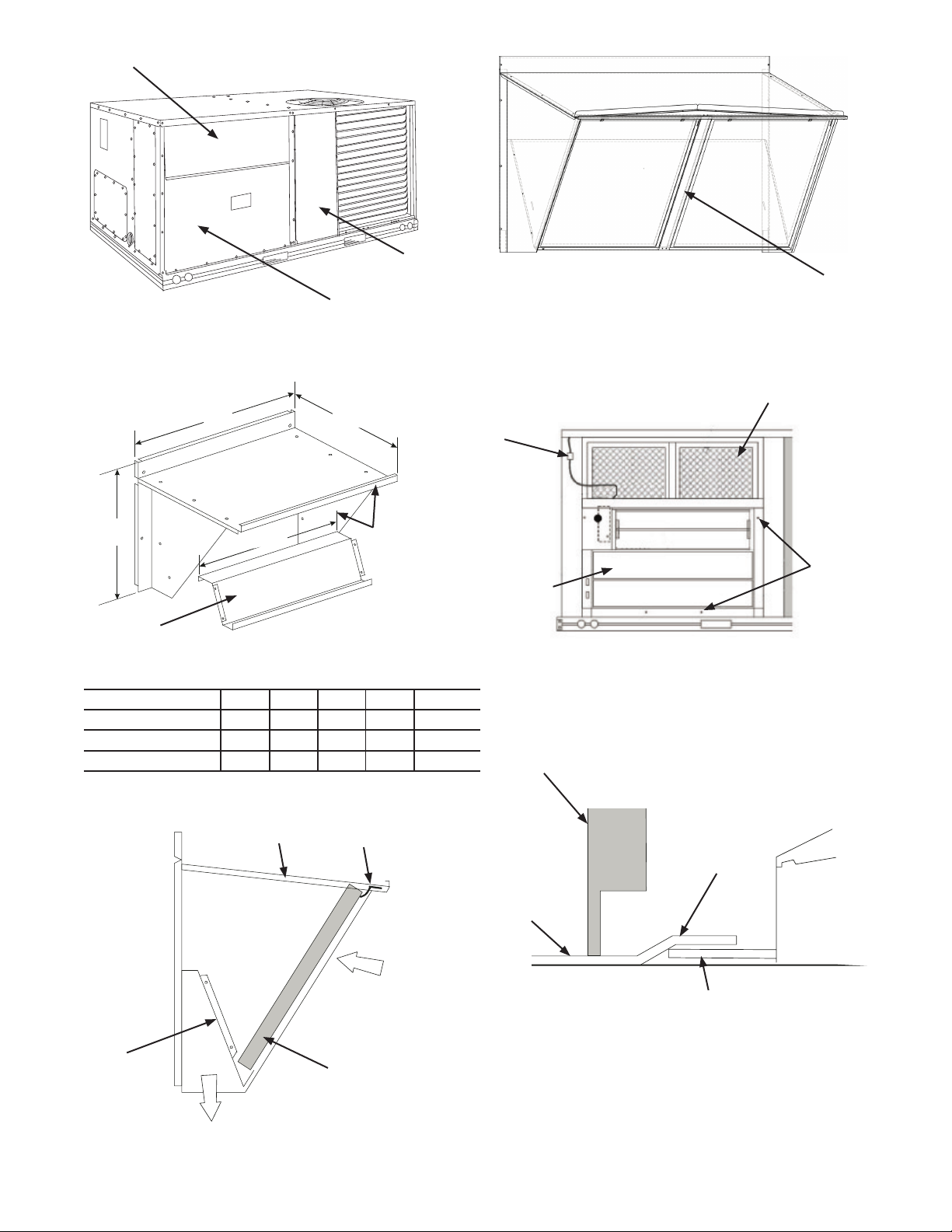
Filter Access Panel
Fig. 2 - Typical Outdoor-Air Section
Outdoor-Air Opening and
Indoor Coil Access Panel
Access Panel Locations
A
B
Compressor
Access Panel
Wiring
Harness
Hood Filter
Divider
Fig. 4A - Hood for Extra Large Cabinet
HVAC Unit Filters
C
Hood Divider
D
Hood Top and
Side Assembly
Fig. 3 - Hood Assembly
ECONOMIZER P/N A B C D SHIP WT.
CRECOMZR076A00 33.37” 17.43” 19.05” 29.5” 55 lb
CRECOMZR078A00 40.37” 22.28” 24.48” 36.27” 80lb
CRECOMZR080A00 52.92” 27.03” 33.41” 49.92” 98lb
NOTE: The CRECOMZR080A00 hood has 2 aluminum lters and a
hood lter divider that installs between the lters. (See Fig. 5A.)
Hood Top
Filter Clip
Outside Air
EconoMi$er X
Fig. 5 - EconoMi$er X Installed in HVAC Unit
Unit Filter
Rack
Unit Base
Insert
Screw in
EconoMi$er X
Flanges
(Small Cabinet Economizer Shown)
EconoMi$er X
Hold Down Tab
EconoMi$er X
Hood
Divider
EconoMi$er IV Rear Flange
Fig. 6 - Rear EconoMi$er X Flange Installation
(Small and Large Cabinet)
Cleanable
Aluminum Filter
Barometric
Airow
Fig. 4 - Filter Installation
3
Page 4
14. While everything is open install and wire any other accessories
Plug 10-pin plug from
and/or sensors as applicable and convenient, per their installation
instructions and/or the Conguration section of this instruction.
Some accessories require that unit ducting already be installed.
NOTE: If also installing a power exhaust accessory, skip step 16 and
follow the power exhaust instructions instead.
16. Install the EconoMi$er X hood over the EconoMi$er X. Use
screws provided.
17. The W7220 EconoMi$er X controller is shipped mounted to a
bracket. Install the controller / bracket in the top left corner of
the unit control box as shown in wiring diagram, Fig. 8. Screw in
place through pre-punched holes.
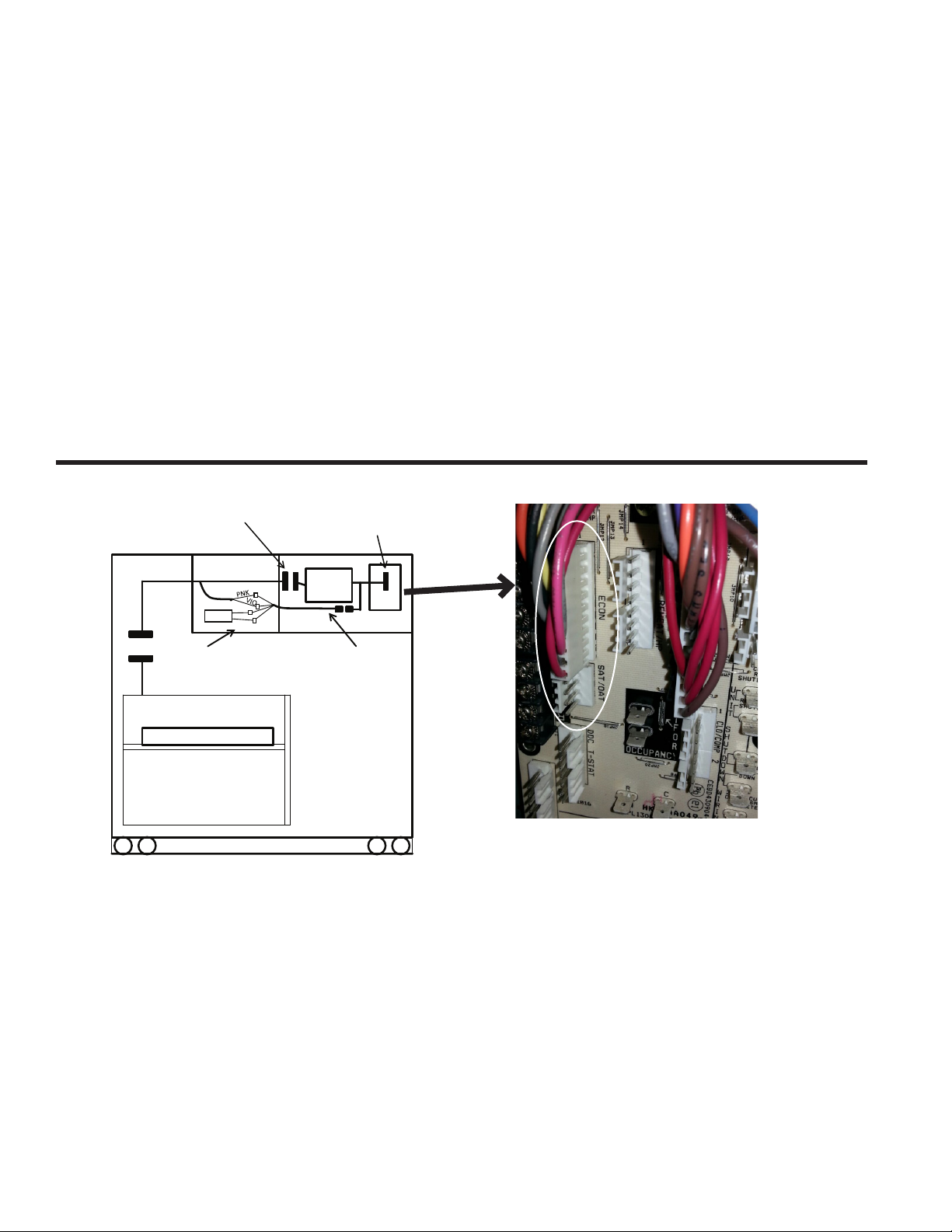
18. For 1 and 2 speed units connect the plugs coming from the
controller as shown in wiring diagram, Fig. 7 and 8A.
NOTE: Provided 48TMHSRSE--A20 harness will be connected as
shown below.
19. For 3 speed (48/50LC 07-12) units, the harness attached to the
W7220 econoMi$er X controller must be removed, and can be
discarded. Locate harness 48LCHSRADH--A00 shipped in
plastic bag in the control box of unit. Attach this harness to the
W7220 controller as shown in Fig 8B and 8C.
NOTE: Harness 48TMHSRSE--A20 provided with economizer is not
used with 3 speed (48/50LC 07-12) units.
20. Adjust controller settings (minimum position, outside air, etc.) per
instructions detailed later in this instruction.
21. Follow all local and other applicable codes.
Unplug the 10-pin plug from
PL6 from the Central Terminal
Board (in control box) and plug
into 10-pin plug from W7220
Indoor Blower
Section
SAT
PL6
Connect SAT sensor and Pink
and Violet wires from PL6 to
the 48TMHSRSE—A20
harness.
BRN
ORN
Control box
W7220 into ECONO
terminals on Central
Terminal Board
W7720
48TMHSRSE--A20
harness with 4- pin
plug
Central
Term Brd
See Picture
ECONO
Economizer X
Fig. 7 - Harness Detail
WIRING INSTRUCTIONS FOR 1 AND 2 SPEED UNITS:
A. Install W7220 (with harnesses attached) in unit control box. See
wiring diagram in instructions.
B. Unplug econo harness from PL6 with 10-pin plug shown above in
picture, from Central Terminal Board (CTB).
C. Attach 10-pin plug disconnected from (CTB) to 10- pin plug
harness from W7220 controller.
D. Connect other 10-pin plug from W7220 controller into ECONO
terminals on CTB. See picture above.
E. Connect 4-pin plug from the W7220 controller to the 4-pin
48TMHSRSE—A20 harness provided with economizer accessory.
F. Route 48TMHSRSE—A20 harness back to the indoor blower
section of the unit.
G. Mount Supply (or Mixed) Air Temperature sensor, and connect
Brown and Orange wires from harness to the SAT.
H. Connect Pink and Violet wires from 48TMHSRSE—A20 harness
to the Pink and Violet wires from PL6 economizer harness
4
Page 5
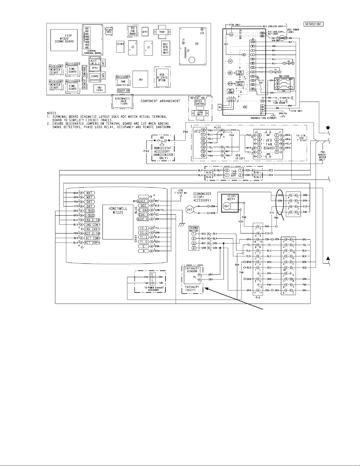
48TMHSRSE--A20
If using HH57AC081 outside air
enthalpy accessory, the OAT must be
removed and disconnected. Set sensor
dip-switches, see Table 11.
Fig. 8A - Typical EconoMi$er X Wiring Diagram For 1 and 2 Speed Units
(2 Speed Diagram Shown)
Harness
5
Page 6
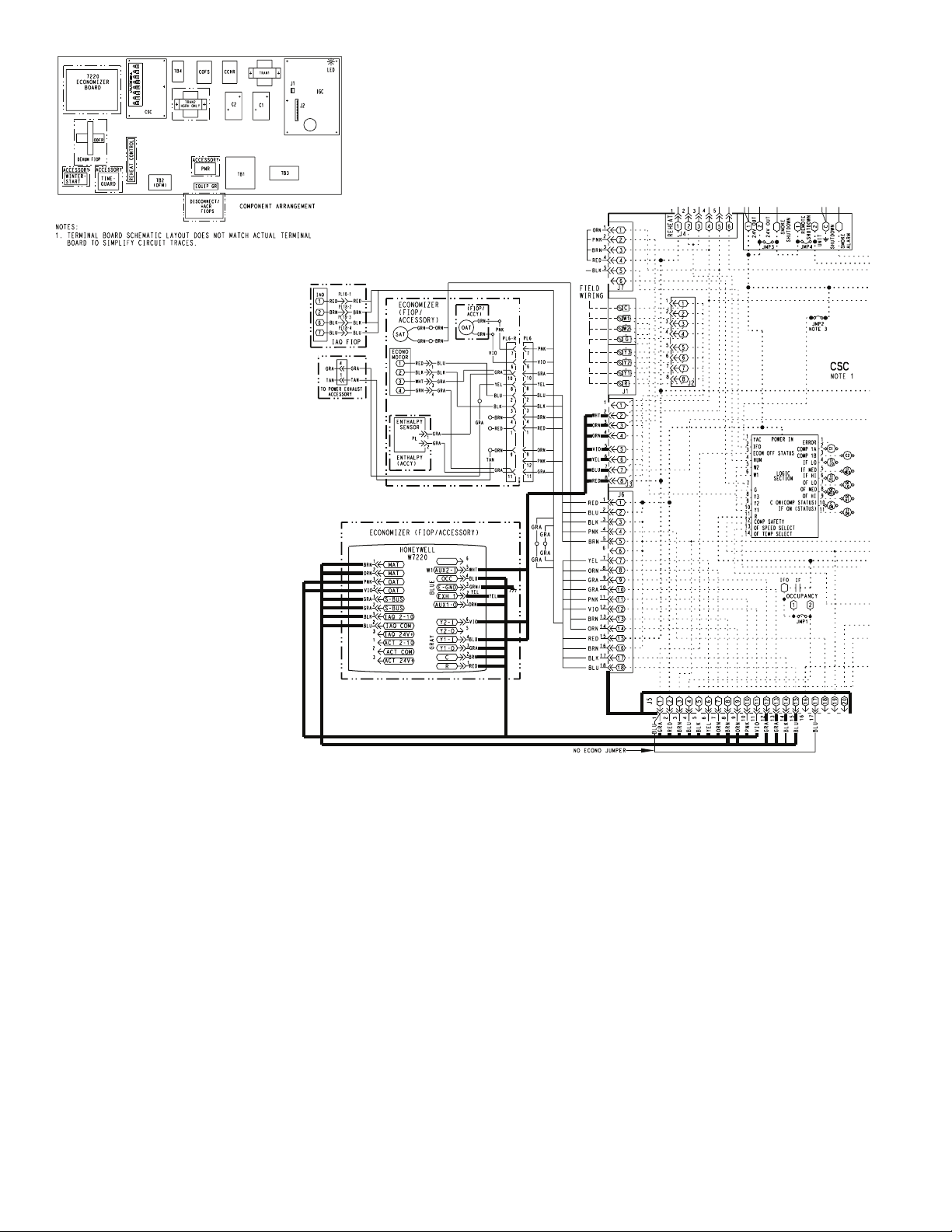
Fig. 8B - Typical EconoMi$er X Wiring Diagram For 3 Speed Units (48/50LC 07-12)
(See 3 Speed Unit Instructions for Complete Diagram)
NOTES:
1. Wires shown in bold are part of 48LCHSRADH--A00 harness
which is provided with 48/50LC 07-12 3 speed units.
2. Harness 48TMHARSE--A20 which is provided with
economizer accessory is not used on 3 speed units.
6
Page 7

FIELD ATTACH TO W7220 CONTROLLER
CONNECT TO UNIT
(Provided with 3 Speed Units, Field Attached to W7220 Controller)
Fig. 8C - 48LCHSRADH--A00 Harness for 3 Speed Units (48/50LC 07-12)
BOARD
UNIT TERMINAL
CONNECT TO
TERMINAL BOARD
7
Page 8

Thermostat
Connection
Access Panel
Center Post
Heating Access
Panel
Indoor Fan Motor
Access Panel
Fig. 9 - Typical Indoor Fan Motor
Access Panel Locations
Mixed Air
Temperature
Sensor
Mounting
Location
Mixed Air
Temperature
Sensor
To Unit
Control Box
Fig. 10 - Mixed Air Sensor Placement
EconoMi$er X
The eld-installed accessory consist of the following:
• Low leak economizer assembly
• W7220 economizer controller
• HH79ZZ007 Mixed (supply) air temperature sensor
• HH79ZZ007 outside air temperature air sensor
• 48TMHSRSE--A20 harness (not used on 3 speed (48/50LC 07-
12) units.
W7220 Economizer
The economizer controller used on electro mechanical units is a
Honeywell W7220 which is to be located in the RTU base unit’s Control
Box. See the Installation Instruction for your base unit for the location
of the Control Box access panel.
The W7220 controller provide the following:
• 2-line LCD interface screen for setup, conguration and
troubleshooting.
• On-board fault detection and diagnostics
• Sensor failure loss of communications identication
• Automatic sensor detection
• Capabilities for use with multiple-speed indoor fan systems
User Interface
The user interface consists of a LCD display and a 4-button keypad on
the front of the economizer controller.
Fig. 11 - W7220 Controller
Using the Keypad with Menus
To use the keypad when working with menus:
• Press the ▲ (Up arrow) button to move to the previous menu.
• Press the ▼ (Down arrow) button to move to the next menu.
• Press the (Enter) button to display the rst item in the currently
displayed menu.
• Press the ↑ (Menu Up/Exit) button to exit a menu’s item and
return to the list of menus.
Using the Keypad with Settings and Parameters
To use the keypad when working with Setpoints, System and Advanced
Settings, Checkout tests and Alarms:
1. Navigate to the desire menu.
2. Press the (Enter) button to display the rst item in the currently
displayed menu.
3. Use the ▲ and ▼ buttons to scroll to the desired parameter.
4. Press the (Enter) button to display the value of the currently
displayed item.
5. Press the ▲ button to increase (change) the displayed parameter
value.
6. Press the ▼ button to decrease (change) the displayed parameter
value.
NOTE: When values are displayed, pressing and holding the
▲ or ▼ button causes the display to automatically increment.
7. Press the (Enter) button to accept the displayed value and store
it in nonvolatile RAM.
8. “CHANGE STORED” displays.
9. Press the (Enter) button to return to the current menu parameter.
10. Press the ↑ (Menu Up/Exit) button to return to the previous
menu.
Menu Structure
Table 5 illustrates the complete hierarchy of menus and parameters for
the EconoMi$er X system.
The Menus in display order are:
• STATUS
• SETPOINTS
• SYSTEM SETUP
• ADVANCED SETUP
• CHECKOUT
• ALARMS
Keypad
The four navigation button (see Fig. 11) are used to scroll through the
menus and menu items, select menu items, and to change parameter and
conguration settings.
IMPORTANT NOTE: The default setting on the W7220 controller
is for a “Fan Type” with 2 speed, which is correct for 2 or 3 speed
units (48/50LC 07-12). If your unit is 1 (single) speed, the setting
under SYSTEM SETUP > FAN TYPE must be changed to 1 speed.
8
Page 9

IMPORTANT: Table 4 illustrates the complete hierarchy. Your menu parameters may be different depending on your conguration.
For example if you do not have a DCV (CO2) sensor, then none of the DCV parameters appear.
a
Notes
Menu Parameter
Parameter
Default
Value
Table 5 ─ Menu Structure
Parameter
Range and Increment
b
STATUS ECON AVAIL NO YES/NO YES = economizing available; the system can use
outside air for free cooling when required
ECONOMIZING NO YES/NO YES = outside air being used for 1st stage cooling
OCCUPIED NO YES/NO YES = OCC signal received from space thermostat
or unitary controller
YES = 24 Vac on terminal OCC.
NO = 0 Vac on terminal OCC.
HEAT PUMP n/a
c
COOL
HEAT
Displays COOL or HEAT when system is set to heat pump
(Non-conventional)
COOL Y1─IN OFF ON/OFF Y1─I signal from space thermostat or unitary controller for
cooling stage 1.
ON = 24 Vac on terminal Y1─I
OFF = 0 Vac on terminal Y1─I
COOL Y1─OUT OFF ON/OFF Cool stage 1 Relay Output to stage 1 mechanical cooling
(Y1─OUT terminal)
COOL Y2─IN OFF ON/OFF Y2─I signal from space thermostat our unitary controller for
second stage cooling.
ON = 24 Vac on terminal Y2─I
OFF = 0 Vac on terminal Y2─I
COOL Y2─OUT OFF ON/OFF Cool Stage 2 Relay Output to mechanical cooling
(Y2─OUT terminal)
MA TEMP _ _ . _oF 0 to 140oF Displays value of measured mixed air from MAT sensor.
Displays _ _ . _ oF if not connected, short or out-of-range.
DA TEMP _ _ . _oF 0 to 140oF Displays when Discharge Air sensor is connected and
displays measured discharge temperature.
Displays _ _ . _oF if sensor sends invalid value, if not connected, short or out-of-range.
OA TEMP _ _ . _oF -40 to 140oF Displays measured value of outdoor air temperature.
Displays _ _ . _oF if sensor sends invalid value, short or
out-of-range.
OA HUM _ _% 0 to 100% Displays measured value of outdoor humidity from OA
sensor.
Displays _ _% if not connected short, or out-of-range.
RA TEMP _ _ . _oF 0 to 140oF Displays measured value of return air temperature from
RAT sensor.
Displays _ _ . _oF if sensor sends invalid value, if not
connected, short or out-of-range
RA HUM _ _% 0 to 100% Displays measured value of return air humidity from RA
sensor.
Displays _ _% if sensor sends invalid value, if not connected, short or out-of-range
IN CO2 _ _ _ppm 0 to 2000 ppm Displays value of measured CO2 from CO2 sensor. Invalid if
not connected, short or out-of-range
DCV STATUS n/a ON/OFF Displays ON if above setpoint and OFF if below setpoint,
and ONLY if a CO2 sensor is connected.
DAMPER OUT 2.0V 2.0 to 10.0V Displays voltage output to the damper actuator.
EXH1 OUT OFF ON/OFF Output of EXH1 terminal:
ON = relay closed
OFF = relay open
EXH2 OUT OFF ON/OFF Output of AUX terminal; displays only if AUX = EXH2
ERV OFF ON/OFF Output of AUX terminal; displays only if AUX = ERV
MECH COOL ON 0 0,1, or 2 Displays stage of mechanical cooling that is active.
9
Page 10

Table 5 ─ Menu Structurea (cont)
Menu Parameter
Default
Value
SETPOINTS MAT SET 53oF 38 to 65oF;
LOW T LOCK 32oF -45 to 80oF;
DRYBLB SET 63oF 48 to 80oF;
ENTH CURVE ES3 ES1,ES2,ES3,ES4, or
DCV SET 1100ppm 500 to 2000ppm;
MIN POS 4.4 V 2 to 10 Vdc Displays ONLY if a CO2 sensor is NOT connected
Parameter
VENTMAX With 2-speed
4.4 V 2 to 10 Vdc
fan units VENTMAX
L (low speed fan) and
VENTMAX H (high speed
fan) settings are required
VENTMAX L 6 V
VENTMAX H 4.4 V
VENTMIN With 2-speed
2.8 V 2 to 10 Vdc
fan units VENTMIN L (low
speed fan) and VENTMIN
H (high speed fan) set
VENTMIN L 3.7 V
VENTMIN H 2.8 V
ERV OAT SP 32oF 0 to 50oF;
EXH1 SET With 2-speed
50% 0 to 100%;
fan units Exh1 L (low
speed fan) and Exh1 H
(high speed fan) settings
are required
Exh1 L 65%
Exh1 H 50%
EXH2 SET With 2-speed
75% 0 to 100%;
fan units Exh2 L (low
speed fan) and Exh2 H
(high speed fan) settings
are required
Exh2 L 80%
Exh2 H 75%
SYSTEM
INSTALL 01/01/10 Display order = MM/DD/YY
SETUP
UNITS DEG
o
F
EQUIPMENT CONV Conventional or HP CONV = conventional; HP O/B = Enable Heat Pump mode. Use AUX2 I
AUX2 I W SD/W or HP(O)/HP(B) In CONV mode: SD + Enables conguration of shutdown (default); W
FAN TYPE 2 speed 1 speed/2 speed
FAN CFM 5000cfm 100 to 15000 cfm;
AUX OUT NONE NONE
OCC INPUT INPUT or ALWAYS When using a setback thermostat with occupancy out (24 Vac), the 24
Parameter
Range and Increment
increment by 1
increment by 1
increment by 1
ES5
increment by 100
or
100 to 9990 cfm
increment by 10
or 100 to 9990 cfm
increment by 10
increment by 1
increment by 1
increment by 1
o
F or oC Sets economizer controller in degrees Fahrenheit or Celsius
increment by 100
ERV
EXH2
SYS
b
Notes
Setpoint determines where the economizer will modulate the OA
damper to maintain the mixed air temperature.
Setpoint determines outdoor temperature when the mechanical cooling
cannot be turned on. Commonly referred to as the Compressor lockout.
Setpoint determines where the economizer will assume outdoor air
temperature is good for free cooling; e.g.; at 63oF unit will economize at
62oF and below and not economize at 64oF and above. There is a 2oF
deadband.
Enthalpy boundary “curves” for economizing using single enthalpy
Displays only if CO2 sensor is connected. Setpoint for Demand Control
Ventilation of space. Above the setpoint, the OA dampers will modulate
open to bring in additional OA to maintain a space ppm level below the
setpoint.
Displays only if a CO2 sensor is connected. Used for Vbz (ventilation
max cfm) setpoint. Displays 2 to 10 V if <3 sensors (RA,OA, and MA).
In AUTO mode dampers controlled by CFM
Displays only if a CO2 sensor is connected. Used for Ba (ventilation min
cfm) setpoint. Displays 2 to 10 V if <3 sensors (RA, OA, and MA). Va
is only set if DCV is used. This is the ventilation for less than maximum
occupancy of the space. In AUTO mode dampers controlled by CFM.
Only when AUX1 O = ERV
Setpoint for OA damper position when exhaust fan 1 is powered by the
economizer.
Setpoint for OA damper position when exhaust fan 2 is powered by the
economizer. Only used when AUX is set to EHX2.
Setting order = DD, MM, then YY.
for Heat Pump input from thermostat or controller.
= Informs controller that system is in heating mode. In HP O/B mode:
HP(O) = energize heat pump on Cool (default); HP(B) = energize heat
pump on heat.
Sets the economizer controller for operation of 1 speed or 2 speed
supply fan. (Note: for 3 speed units (48/50LC 07-12), setpoint is a 2
speed.)
This is the capacity of the RTU. The value is found in the Project
Submittal documents for the specic RTU.
• NONE = not congured (output is not used)
• ERV = Energy Recovery Ventilatio
n
• EXH2 = second damper position relay closure for second exhaust fan
• SYS = use output as an alarm signal
Vac is input “INPUT” to the OCC terminal. If no occupancy output from
the thermostat then change program to “ALWAYS” OR add a jumper
from terminal R to OCC terminal
10
Page 11

Table 5 ─ Menu Structurea (cont)
Menu Parameter
Default
Value
Parameter
SYSTEM
FACTORY DEFAULT NO NO or YES Resets all set points to factory defaults when set to YES. LCD will
SETUP
ADVANCED
MA LO SET 45oF 35 to 55oF;
SETUP
FREEZE POS CLO CLO or MIN Damper position when freeze protection is active (closed or MIN POS).
CO2 ZERO 0ppm 0 to 500 ppm;
CO2 SPAN 2000ppm 1000 to 3000 ppm;
STG3 DLY 2.0h 0 min, 5 min, 15 min,
SD DMPR POS CLO CLO or OPN Indicates shutdown signal from space thermostat or unitary controller.
DCVCAL ENA MAN MAN (manual)
MAT T CAL 0.0oF +/-2.5oF Allows for the operator to adjust for an out of calibration temperature
OA T CAL 0.0oF +/-2.5oF Allows for the operator to adjust for an out of calibration temperature
OA H CAL 0% RH +/-10% RH Allows for operator to adjust for an out of calibration humidity sensor.
RA T CAL 0.0oF +/-2.5oF Allows for the operator to adjust for an out of calibration temperature
RA H CAL 0% RH +/-10% RH Allows for operator to adjust for an out of calibration humidity sensor.
DA T CA; 0.0oF +/-2.5oF Allows for the operator to adjust for an out of calibration temperature
CHECKOUT DAMPER VMIN─HS n/a n/a Positions damper to VMIN position
DAMPER VMAX─HS n/a n/a Positions damper to VMAX position
DAMPER OPEN n/a n/a Position damper to the full open position.
DAMPER CLOSE n/a n/a Positions damper to the fully closed position
CONNECT Y1─O n/a n/a Closes the Y1─O relay (Y1─O)
CONNECT Y2─O n/a n/a Closes the Y2─O relay (Y2─O)
CONNECT AUX n/a n/a Energizes the AUX output. If Aux setting is:
ALARMS(#) Alarms display only when they are active. The menu title
MA T SENS ERR n/a n/a Mixed air sensor has failed or become disconnected - check wiring then
CO2 SENS ERR n/a n/a CO2 sensor has failed, gone out of range or become disconnected -
OA SYLK T ERR n/a n/a Outdoor air enthalpy sensor has failed or become disconnected - check
OA SYLK H ERR n/a n/a
RA SYLK T ERR n/a n/a Return air enthalpy sensor has failed or become disconnected - check
RA SYLK H ERR n/a n/a
DA SYLK T ERR n/a n/a Discharge air sensor has failed or become disconnected - check wiring
OA SENS T ERR Outdoor air temperature sensor has failed or become disconnected -
Parameter
Range and Increment
Incremented by 1
o
Increment by 10
Increment by 10
then 15 min intervals.
Up to 4 h or OFF
AUTO
b
Notes
briey ash YES and change to NO but all parameters will change to
the factory default values.
Temperature to achieve Freeze Protection (close damper and alarm if
temperature falls below setup value).
CO2 ppm level to match CO2 sensor start level.
CO2 ppm span to match CO2 sensor.
Delay after stage 2 cool has been active. Turns on 2nd stage of cooling
when economizer is 1st stage and mechanical cooling is 2nd stage.
Allows three stages of cooling, 1 economizer and 2 mechanical.
OFF = no Stage 3 cooling
When controller receives 24 Vac input on the SD terminal in conventional mode, the OA damper will open if programmed for OPN and OA
damper will close if programmed for CLO. All other controls, e.g., fans,
etc. will shut off.
Turns on the DCV automatic control of the dampers. Resets ventilation
based on the RA, OA, and MA sensor conditions. Requires all 3 RA,
OA, and MA sensors.
sensor.
sensor.
sensor.
sensor.
Exhaust fan contacts enable during the DAMPER OPEN test. Make
sure you pause in the mode to allow exhaust contacts to energize due
to the delay in the system.
• NONE ─ not action taken
• ERV ─ 24 Vac out. Turns on or signals an ERV that the conditions
are not good for economizing but are for ERV operation.
d
• SYS ─ 24 Vac out. Issues a system alarm
“ALARMS(#)” includes the number of active alarms in parenthesis ( ). When using SYLK bus sensors, “SYLK” will appear on the
screen, and when using 20k OA temperature sensors, “SENS T”
will appear on the screen
replace sensor if the alarm continues.
check wiring then replace sensor if the alarm continues.
wiring then replace sensor if the alarm continues.
wiring then replace sensor if the alarm continues.
then replace sensor if the alarm continues
check wiring then replace if the alarm continues.
11
Page 12

Table 5 ─ Menu Structurea (cont)
Menu Parameter
Default
Value
Parameter
ALARMS(#)
ACT ERROR n/a n/a Actuator has failed or become disconnected - check for stall, over
CONTINUED
FREEZE ALARM n/a n/a Check if outsoor temperature is below the LOW Temp Lockout on
SHUTDOWN ACTIVE n/a n/a AUX2 IN is programmed for SHUTDOWN and 24 V has been applied
DMP CAL RUNNING n/a n/a If DCV Auto enalbe has been programmed, when the Jade is
DA SENS ALM n/a n/a Discharge air temperature is out of the range set in the ADVANCED
SYS ALARM n/a n/a When AUX1-0 is set to SYS and there is any alarm (e.g., failed
ACT UNDER V n/a n/a Voltage received by Actuator is above expected range.
ACT OVER V n/a n/a Voltage recieved by Actuator is below expected range.
ACT STALLED n/a n/a Actuator stopped before achieving commanded position.
a
Table 5 illustrates the complete hierarchy. Your menu parameters may be different depending on your conguration.
For example if you do not have a DCV (CO2) sensor, then none of the DCV parameters appear
b
When values are displayed, pressing and holding the ▲ or ▼ button causes the display to automatically increment.
c
n/a = not applicable
d
ERV Operation: When in Cooling mode AND the conditions are NOT OK for economizing - the ERV terminal will be energized.
In the Heating mode the ERV terminal will be energized when the OA is below the ERV OAT setpoint in the setpoint menu.
Parameter
Range and Increment
b
Notes
voltage, undervoltage and actuator count. Replace actuator if damper
is moveable and supply voltage is between 21.6 V and 26.4 V. Check
actuato count on STATUS menu
setpoint menu. Check if Mixed air temperature on STATUS menu is
below the Lo Setpoint on Advanced menu. When conditions are back in
normal range then the alarm will go away.
to AUX 2IN terminal.
completing a calibration on the dampers, this alarm will display. Wait
until the calibration is completed and the alarm will go away. Must have
OA, MA and RA sensors for DCV calibration; set up in the Advanced
setup menu.
SETUP Menu. Check the termperature of the discharge air.
sensors, etc.), the AUX1-0 terminal has 24 Vac out.
12
Page 13

Checkout Tests
Use the Checkout menu (see Table 5) to test the damper operation and
any congured outputs. Only items that are congured are shown in
the Checkout menu.
NOTE: See User Interface on page 3 for information about menu navigation and use of the keypad.
To perform a Checkout test:
1. Scroll to the desired test in the Checkout menu using the ▲ and
▼ buttons.
2. Press the button to select the item.
3. RUN? appears.
4. Press the button to start the test.
5. The unit pauses and then displays IN PROGRESS.
6. When the test is complete, DONE appears.
7. When all desired parameters have been tested, press the ↑ (Menu
up) button to end the test.
Checkout test can be performed at any time during the operation of the
system as a test that the system is operable.
CAUTION
!
EQUIPMENT DAMAGE HAZARD
Failure to follow this caution may result in damage to equipment
Be sure to allow enough time for compressor startup and shutdown
between checkout tests so that you do not short-cycle the compressors.
Table 6 - Economizer Module -
Left Hand Terminal Blocks
Label Type Description
Top Left Terminal Block
MAT
MAT
OAT
OAT
S─BUS
S─BUS
20k NTC
and COM
20k NTC
and COM
S─BUS
(Sylk Bus)
Mixed Air Temperature Sensor
(Polarity insensitive connections)
Outdoor Air Temperature Sensor
(Polarity insensitive connection)
Enthalpy Control Sensor
(Polarity insensitive connection)
Bottom Left Terminal Block
IAQ 2─10 2─10 Vdc Air Quality Sensor Input
(e.g. CO2 sensor)
IAQ COM COM Air Quality Sensor Common
IAQ 24V 24 Vac Air Quality Sensor 24 Vac Source
ACT 2─10 2─10 Vdc Damper Actuator Output (2─10 Vdc)
ACT COM COM Damper Actuator Output Common
ACT 24V 24 Vac Damper Actuator 24 Vac Source
Table 7 - Economizer Module -
Right Hand Terminal Blocks
SETUP AND CONFIGURATION
W7220 Economizer Module Wiring
Use Fig. 12 and Tables 6 and 7 to locate the wiring terminals for the
economizer module.
NOTE: The four terminal blocks are removable. You can slide out
each terminal block, wire it, and then slide it back into place.
HJW10
50048848-002
NA
AUX2-
OCC
E-GND
EXH1
AUX1-O
Y2-
Y2-O
Y1-
Y1-O
C
R
Rev. A
MAT
MAT
OAT
OAT
S-BUS
S-BUS
IAQ 2-10
IAQ COM
IAQ 24V
ACT 2-10
ACT COM
ACT 24V
50040839-001
Rev. G
MA
MA
OA
OA
SB
SB
SB
SB
SB
SB
V
C
R
V
C
R
NA
NA
A2
OCC
EX
A1
Certied FDD Product
California Title 24, Part 6
www.energy.ca.gov
Y2I
Y2O
Y1I
Y1O
C
R
Fig. 12 - W7220 Economizer Module Terminal
Connection Labels
Label Type Description
Top Right Terminal Block
n/a The rst terminal is not used
AUX2 I 24 Vac IN Shut Down (SD) or Heat (W)
Conventional only
and
Heat Pump Changeover (O?B) in
Heat Pump mode.
OCC 24 Vac IN Occupied / Unoccupied Input
E - GND E─GND Earth Ground - System Required
EXH1 24 Vac OUT Exhaust Fan 1 Output
AUX1 O 24 Vac OUT Programmable:
Exhaust fan 2 output
or
ERV
or
System alarm output
Bottom Right Terminal Block
Y2─1 24 Vac IN Y2 in - Cooling Stage 2 Input from
space thermostat
Y2─O 24 Vac OUT Y2 out - Cooling Stage 2 Output to
stage 2 mechanical cooling
Y1─I 24 Vac IN Y1 in - Cooling Stage 2 Input from
space thermostat
Y1─O 24 Vac OUT Y1 out - Cooling Stage 2 Output to
stage 2 mechanical cooling
C COM 24 Vac Common
R 24 Vac 24 Vac Power (Hot)
Time-out and Screen Saver
When no buttons have been pressed for 10 minutes, the LCD displays a
screen saver, which cycles through the Status items. Each Status item
displays in turn and cycles to the next item after 5 seconds.
13
Page 14

HH79ZZ007 Dry Bulb Sensor
Economizers are shipped standard with an HH79ZZ007 outside air dry
bulb sensor, which looks like an eyelet terminal with 2 green wires.
This sensor is factory installed on the front of the economizer in the out-
20k Sensor
GREEN
1/4 Terminal (2)
side air stream. System default setting (high temp limit) is 63 degrees F,
and has a range of 48 to 80 degrees F. Note: a 2nd HH79ZZ007 sensor
is provided for mixed (supply) air temperature.
NOTE: California high temperature setting requirements by region are
shown below.
Device Type
a
Climate Zones
Fig. 12A - HH79ZZ007 Sensor
Required High Limit (Economizer Off When):
Description
GREEN
1, 3, 5, 11-16 Outdoor air temperature exceeds 75°F
Fixed Dry Bulb
2, 4, 10 Outside air temperature exceeds 73°F
6, 8, 9 Outdoor air temperature exceeds 71°F
7 Outdoor air temperature exceeds 69°F
1, 3, 5, 11-16 Outdoor air temperature exceeds return air temperature
Differential Dry Bulb
2, 4, 10 Outdoor air temperature exceeds return air temperature minus 2°F
6, 8, 9 Outdoor air temperature exceeds return air temperature minus 4°F
7 Outdoor air temperature exceeds return air temperature minus 6°F
Fixed Enthalpyb + Fixed
Dry Bulb
a
Only the high limit control devices listed are allowed to be used and at the setpoints listed. Others such as Dew Point, Fixed
All
Outdoor air enthalpy exceeds 28 Btu/lb of dry airb or
Outdoor air temperature exceeds 75°F
Enthalpy, Electronic Enthalpy, and Differential Enthalpy Controls, may not be used in any climate zone for compliance with Section 140.4(e)1 unless approval for use is provided by the Energy Commission Executive Director.
b
At altitudes substantially different than sea level, the Fixed Enthalpy limit value shall be set to the enthalpy value at 75°F and
50% relative humidity. As an example, at approximately 6,000 foot elevation, the xed enthalpy limit is approximately 30.7 Btu/lb.
Table 8 - California Title 24 Regional High Limit Dry Bulb Temperature Settings
TABLE 140.4-B AIR ECONOMIZER HIGH LIMIT SHUT OFF CONTROL REQUIREMENTS
Fig. 13 - Single Enthalpy Curve boundaries
14
Page 15

Table 9 - Single Enthalpy and Dual Enthalpy High Limit Curves
Enthalpy
Curve
ES1 80.0 60.0 28.0 80.0 36.8 66.3 80.1
ES2 75.0 57.0 26.0 75.0 39.6 63.3 80.0
ES3 70.0 54.0 24.0 70.0 42.3 59.7 81.4
ES4 65.0 51.0 22.0 65.0 44.8 55.7 84.2
ES5 60.0 48.0 20.0 60.0 46.9 51.3 88.5
HL 86.0 66.0 32.4 86.0 38.9 72.4 80.3
Temp.
Dry Bulb (oF)
Temp.
Dewpoint (oF)
Enthalpy
(btu/lb/da)
Temp (oF) Humidity %RH Temp (oF)
Point P1 Point P2
Enthalpy Settings (Optional Accessory)
If installing the optional HH57AC081 enthalpy sensor. The
HH79AH001 dry bulb outside air sensor must rst be removed. Wire
enthalpy to S-BUS connections on W7220 controller thru (2) gray
wires.
When the OA temperature, enthalpy and dew point are below the
respective setpoints, the Outdoor Air can be used for economizing. Fig.
13 shows the new single enthalpy boundaries in the W7220. There are
5 boundaries (setpoints ES1 thru ES5), which are dened by dry bulb
temperature, enthalpy and dew point.
Refer to Table 9 for ENTH CURVE setpoint values.
To use enthalpy the W7220 must have a HH57AC081 enthalpy control
sensor for OA. The W7220 calculates the enthalpy and dewpoint using
the OA temperature and humidity input from the OA sensor. When the
OA temperature, OA humidity and OA dew point are all below the
selected boundary, the economizer sets the economizing mode to YES,
economizing is available.
When all of the OA conditions are above the selected boundary, the
conditions are not good to economize and the mode is set to NO.
Fig. 13 shows the 5 current boundaries. There is also a high limit
boundary for differential enthalpy. The high limit boundary is ES1
when there are no stages of mechanical cooling energized and HL (high
limit) when a compressor stage is energized.
Table 8 provided the values for each boundary limit.
If using OA enthalpy sensor HH57AC081 accessory, remove and
discard the dry bulb sensor shipped with the economizer. System
enthalpy default is ES3 curve.
See Table 8 for California Title 24 high limit settings.
Enthalpy control Sensor Conguration
The optional Enthalpy Control sensor (Part Number: HH57AC081)
communicates with the W7220 Economizer controller on the two-wire
communications bus and can either be wired using a two pin header or
using a side connector. This sensor can be used for outdoor enthalpy,
or indoor dry bulb or enthalpy depending on the dip-swtich setting.
System enthalpy default is ES3 curve. See Table 8 for California Title
24 high limit settings.
Use Fig. 14 and Table 10 to locate the wiring terminals for each
Enthalpy Control sensor.
Use Fig. 14 and Table 11 to set the DIP switches for the desired use of
the sensor.
If using differential (return) enthalpy or temperature, see Table 8 for
California Title 24 setting requirements by region.
(Used for Outdoor Enthalpy, or Indoor Return
Nbr Label
1 S─BUS S─BUS
2 S─BUS S─BUS
a DA = Discharge Air or Supply Sensor
b RA = Return Air
c OA = Outside Air
Fig. 14 - HH57AC081 Accessory
Temperature or Enthalpy)
Table 10 - HH57AC081 Sensor
Wiring Terminations
Terminal
Type Description
S─Bus Communications
(Enthalpy Control Sensor Bus)
S─Bus Communications
(Enthalpy Control Sensor Bus)
Table 11 - HH57AC081 Sensor DIP Switch
Use
DA
RA
OA
DIP Switch Positions for Switches 1,2, & 3
1 2 3
a
b
c
OFF ON OFF
ON OFF OFF
OFF OFF OFF
Humidity
%RH
a
15
Page 16

OPERATION
Cooling, Unit with EconoMi$er X
For Occupied mode operation of EconoMi$er X, here must be a 24-v
signal at terminals R and OCC (provided through PL6-3 from the unit’s
IFC coil). Removing the signal at OCC places the EconoMi$er X
control in Unoccupied mode.
During Occupied mode operation, indoor fan operation will be
accompanied by economizer dampers moving to Minimum Position
setpoint for ventilation. If indoor fan is off, dampers will close. During
Unoccupied mode operation, dampers will remain closed unless a
Cooling (by free cooling) or DCV demand is received.
When free cooling using outside air is not available, the unit cooling
sequence will be controlled directly by the space thermostat. Outside
air damper position will be closed or Minimum Position as determined
by Occupancy mode and fan signal.
When free cooling is available as determined by the appropriate
changeover command (dry bulb, outdoor enthalpy, differential dry bulb
or differential enthalpy), a call for cooling (Y1 closes at the thermostat)
will cause the economizer control to modulate the dampers open and
closed to maintain the unit supply air temperature. Default supply air
temperature is 53°F, with a range of 38° to 70°F. Compressor will not
run.
Should 100% outside air not be capable of satisfying the space
temperature, space temperature will rise until Y2 is closed. The
economizer control will call for compressor operation. Dampers will
modulate to maintain SAT at setpoint concurrent with Compressor 1
operation. The “Low T Temp” setting (default 32°F) will lock out
compressor operation.
When space temperature demand is satised (thermostat Y1 opens),
the dampers will return to Minimum Damper position if indoor fan is
running or fully closed if fan is off.
If accessory power exhaust is installed, the power exhaust fan motors
will be energized by the economizer control as the dampers open above
the EXH1 SET setpoint and will be-energized as the dampers close
below the EXH1 SET setpoint.
Damper movement from full closed to full open (or vice versa) will
take between 1-1/2 and 2-1/2 minutes.
Heating with EconoMi$er X
During Occupied mode operation, indoor fan operation will be
accompanied by economizer dampers moving to Minimum Position
setpoint for ventilation. If indoor fan is off, dampers will close. During
Unoccupied mode operation, dampers will remain closed unless a DCV
demand is received.
When the room temperature calls for heat (W1 closes), the heating
controls are energized.
Demand Controlled Ventilation
If a eld-installed CO2 sensor is connected to the EconoMi$er X control,
a Demand controlled Ventilation strategy will operate automatically.
As the CO2 level in the space increases above the setpoint (on the
EconoMi$er X controller), the minimum position of the dampers will
be increased proportionally, until the Maximum Ventilation setting is
reached. As the space CO2 level decreases because of the increase in
fresh air, the outdoor damper will follow the higher demand condition
from the DCV mode or from the free cooling mode.
DCV operation is available in Occupied and Unoccupied periods with
EconoMi$er X. However, a control modication will be required on
the units to implement the Unoccupied period function.
Table 12 - Damper Position Control, 2-Speed Fan Motor, Economizer Cooling Not Available
INPUT
OCC 0 - V 24 - V 24 - V 24 - V 24 - V
Y1 0 - V 0 - V 24 - V 24 - V 0 - V
Y2 0 - V 0 - V 0 - V 24 - V 0 - V
W1 0 - V 0 - V 0 - V 0 - V 24 - V
SUPPLY FAN
MOTOR SPEED
DAMPER POSITION
NO CI2 SENSOR CLOSED MIN POS MIN POS MIN POS MIN POS
W/ CO2 SENSOR CLOSED
OFF LOW LOW HIGH HIGH
FROM
VENTMIN L
TO
VENTMAX L
FROM
VENTMIN L
TO
VENTMAX L
FROM
VENTMIN H
TO
VENTMAX H
FROM
VENTMIN H
TO
VENTMAX H
16
Page 17

TROUBLESHOOTING
Power Loss (Outage or Brownout)
All setpoints and advanced settings are restored after any power loss
or interruption, as all settings are stored in the Economizer controller’s
non-volatile ash memory.
NOTE If the power goes below 18 Vac, the W7220 controller module
assumes a power loss and the 5 minute power up delay will become
functional when power returns above 18 Vac.
Clearing Alarms
Once the alarm has been identied and the cause has been removed
(e.g. replaced faulty sensor). The can be cleared from the display.
To clear an alarm, perform the following:
1. Navigate to the desired alarm.
2. Press the button.
3. ERASE? displays.
4. Press the button.
5. ALARM ERASED displays.
Alarms
The Economizer module provides alarm messages that display on the
2-line LCD
NOTE: Upon power up, the module waits several seconds before
6. Press the ↑ (Menu up/Exit) button to complete the action and
return to the previous menu.
NOTE: If the alarm still exists after you clear it, it is redisplayed
within 5 seconds.
checking for alarms. This allows time for all the congured devices
(e.g. sensors, actuator) to become operational.
If one or more alarms are present and there has been no keypad activity
for at least 5 minutes, the Alarms menu displays and cycles through the
active alarms.
You can also navigate to the Alarms menus at any time.
See Table 5 for the Alarms menu.
Table 13 - Operating Issues and Concerns
Issue or Concern Possible Cause and Remedy
My outdoor temperature reading on the
STATUS menu is not accurate
If my enthalpy sensor drifts in accuracy
over time, can I re-calibrate it?
Can I go back to factory defaults and start
over?
Will I be able to see the LCD screen when it
is in the unit?
What is a good setpoint for the Mixed Air
Temperature (MAT)?
I am using enthalpy sensors. Why did
the control ask me to input a dry bulb
changeover temperature?
In checkout, the outdoor damper closes when
I command it to open.
How do I set my minimum position? The minimum position is set using the VENTMIN and VENTMAX setup in the
What if my damper does not go completely
closed in the checkout operation?
How do I set the OCC? There are two setting for the OCC setting, INPUT and ALWAYS, INPUT is from the
Does the economizer save my program values if the unit loses power?
If the unit is left in checkout, how long will the
unit stay in checkout mode without input?
Check the sensor wiring:
• Enthalpy sensors are to be wired to the S-Bus terminals.
• Temperature sensors are to be wired to the OAT and MAT terminals.
The sensor is not able to be re-calibrated in the eld. However there is a menu
item under the ADVANCED menu where you are able to input a limited off set in
temperature and humidity for each sensor you have connected to the economizer.
Under the SYSTEM SETUP menu you can change the setpoints to the factory
defaults.
The LCD screen has a backlight that is always illuminated.
The mixed are temperature is the temperature of air that you want to supply to the
space. In a commercial building, this is between 50 to 55oF (10 to 13oC). The mixed
are is the mixing of the return air and the outdoor air.
In the even the humidity sensor in the enthalpy sensors fails, the backup algorithm in
the control is to default to the temperature sensor in the enthalpy sensor.
Check the actuator linkage or rotation. In the CHECKOUT mode, the outdoor damper
should drive open or closed with the return air damper having the opposite effect.
SETPOINTS menu. VENTMIN is the minimum ventilation required when using an
occupancy sensor and VENTMAX is the minimum ventilation when not using an
occupancy sensor for Demand Control Ventilation. The VENTMAX position is set the
dame as with the potentiometer on the analog economizers and is the output voltage
to the damper actuator. The range is 2 Vdc closed OA damper and 10 Vdc open OA
damper.
Check the damper linkage or hub to make sure the damper is able to close
completely.
space thermostat, if it has an occupancy output. ALWAYS is the unit in the occupied
mode, if the economizer is powered (fan on).
Yes, once the changes are stored in the controller they will be stored until they are
changed by the operator.
The unit will remain in checkout for 10 minutes, then return to normal operation.
17
Page 18

Fig. 15 - Barometric Relief Flow Capacity
0
500
1000
1500
2000
2500
0 0.05 0.1 0.15 0.2 0.25 0.3
RELIEF FLOW (CFM)
RETURN DUCT STATIC PRESSURE (in. wg)
Small
Cabinet
Large and
Extra
Large
Cabinet
0
1000
2000
3000
4000
5000
6000
0 0.1 0.2 0.3 0.4
RETURN AIR FL OW (CFM)
RETURN DUCT STATIC PRESSURE DROP (i n. wg)
Small Cabinet
Large Cabinet
Extra Large C abinet
Fig. 16 - Return Air Pressure Drop
Copyright 2014 Carrier Corporation ● 7310 W. Morris St. ● Indianapolis, IN
Manufacturer reserves the right to discontinue, or change at any time, specication or designs without notice and without incurring obligations
Catalog No. IIK-CRECOMZR76-02Edition Date: 04/14
Replaces: IIK-CRECOMZR076-01
18
 Loading...