

Page 1
Small Rooftop Units
3 to 12.5 Tons
(48/50LC 14 Not Included)
Accessory Ultra Low Leak Vertical EconoMi$er® X Accessory
Installation Instructions
Part No: CRECOMZR067A01, CRECOMZR069A01, and CRECOMZR071A01
CONTENTS
Page
SAFETY CONSIDERATIONS . . . . . . . . . . . . . . . . . 1
GENERAL . . . . . . . . . . . . . . . . . . . . . . . . . . . . . . . . . 2
Accessories List . . . . . . . . . . . . . . . . . . . . . . . . . . . 3
Compliance . . . . . . . . . . . . . . . . . . . . . . . . . . . . . . . 3
INSTALLATION . . . . . . . . . . . . . . . . . . . . . . . . . . . . 4
Instructions for 48/50LC 07-12 Units Only . . . . . 10
Installing Optional HH57AC081 Single Outside Air
Enthalpy Sensor . . . . . . . . . . . . . . . . . . . . . . . . 13
Installing Differential Return Air Sensor . . . . . . . 14
California’s Title 24 High Temperature Limit
Settings . . . . . . . . . . . . . . . . . . . . . . . . . . . . . . . 14
Demand Controlled Ventilation (DCV) . . . . . . . . . 14
Remote (Downstairs) Monitoring of Controller’s
Fault Detection and Diagnostics . . . . . . . . . . . 15
GENERAL JADE W7220 CONTROLLER AND
SENSOR INFORMATION . . . . . . . . . . . . . . . . . 16
W7220 Economizer . . . . . . . . . . . . . . . . . . . . . . . . 16
User Interface . . . . . . . . . . . . . . . . . . . . . . . . . . . . 16
Keypad . . . . . . . . . . . . . . . . . . . . . . . . . . . . . . . . . . 16
Using the Keypad with Menus . . . . . . . . . . . . . . . 16
Using the Keypad with Settings and Parameters 16
Menu Structure . . . . . . . . . . . . . . . . . . . . . . . . . . . 16
PROGRAMMING JADE W7220 CONTROLLER . . 16
Setpoints . . . . . . . . . . . . . . . . . . . . . . . . . . . . . . . . 16
System Setup . . . . . . . . . . . . . . . . . . . . . . . . . . . . 17
Checkout Tests . . . . . . . . . . . . . . . . . . . . . . . . . . . 21
W7220 Economizer Module Wiring . . . . . . . . . . . 22
Time-out and Screen Saver . . . . . . . . . . . . . . . . . 22
START-UP AND OPERATION . . . . . . . . . . . . . . . . 22
Cooling, Unit with EconoMi$er® X . . . . . . . . . . . 22
Heating with EconoMi$er® X . . . . . . . . . . . . . . . . 22
TROUBLESHOOTING . . . . . . . . . . . . . . . . . . . . . . 24
Power Loss (Outage or Brownout) . . . . . . . . . . . 24
Alarms . . . . . . . . . . . . . . . . . . . . . . . . . . . . . . . . . . 24
Clearing Alarms . . . . . . . . . . . . . . . . . . . . . . . . . . . 24
• Follow all safety codes.
• Wear safety glasses and work gloves.
• Use care in handling and installing the accessory.
It is important to recognize safety information. This is
the safety-alert symbol . When you see this symbol on
the unit and in instructions or manuals, be alert to the potential for personal injury.
Understand the signal words DANGER, WARNING, CAU-
TION, and NOTE. These words are used with the safety-alert
symbol. DANGER identifies the most serious hazards which
will result in severe personal injury or death. WARNING signifies hazards which could result in personal injury or death.
CAUTION is used to identify unsafe practices, which may result in minor personal injury or product and property damage.
NOTE is used to highlight suggestions which will result
in enhanced installation, reliability, or operation.
WARNING
ELECTRICAL SHOCK HAZARD
Failure to follow this warning could cause personal injury
or death. Before performing service or maintenance operations on the unit, always turn off main power switch to unit
and install lock(s) and lockout tag(s). Unit may have more
than one power switch. Ensure electrical service to rooftop
unit agrees with voltage and amperage listed on the unit rating plate.
CAUTION
CUT HAZARD
Failure to follow this caution may result in personal injury.
Sheet metal parts may have sharp edges or burrs. Use care
and wear appropriate protective clothing, safety glasses and
gloves when handling parts and servicing roof top units.
CAUTION
Failure to follow this caution may result in personal injury
and damage to the unit. Cover the duct opening as a precaution so objects cannot fall into the return duct opening. Be
sure to remove the cover when installation is complete.
SAFETY CONSIDERATIONS
Installation of this accessory can be hazardous due to
system pressures, electrical components and equipment, and
equipment locations (such as a roof or elevated surface).
Only trained qualified installers and service technicians
should install, start up, and service this equipment.
When installing this accessory, observe precautions in
the literature and on any labels attached to the equipment
and all other safety precautions may apply.
Manufacturer reserves the right to discontinue, or change at any time, specifications or designs without notice and without incurring obligations.
Catalog No. 04-53480202-01 Printed in U.S.A. Form IIK-CRECOMZR67-04 Pg 1 11-18 Replaces: IIK-CRECOMZR67-03
The EconoMi$er® X system utilizes the latest technology available for integrating the use of free cooling with mechanical cooling for packaged rooftop units. The code compliant Jade W7220 control system optimizes energy consumption, zone comfort, and equipment cycling by
operating the compressors when the outdoor-air temperature
is too warm, integrating the compressor with outdoor air
when free cooling is available, and locking out the compres-
GENERAL
Page 2
sor when outdoor-air temperature is too cold. Demand control
ventilation is supported.
This EconoMi$er X system can be used with 1 or 2 speed
indoor fan motor units. (All other speed settings listed are for
future use.)
The EconoMi$er X system utilizes gear-drive technology
with a direct-mount spring return actuator that will close
upon loss of power. The EconoMi$er X system comes standard with fault detection and diagnostics (FDD), an outdoor
air temperature sensor, and mixed air temperature sensor (also called supply air temperature sensor). Outdoor enthalpy,
indoor (return) dry bulb or enthalpy, and CO
sensors are
2
available for field installation.
Standard integrated barometric relief dampers provide natural building pressurization control. An optional power exhaust system is available for applications requiring even
greater exhaust capabilities. The power exhaust set point is
adjustable at the EconoMi$er X controller.
See Tables 1-3 for package usage. See Table 4 for package
contents. See Table 5 for sensor usage.
IMPORTANT: These economizers meet all the economizer requirements as specified in ASHRAE 90.1, IECC
and California’s Title 24. Economizer must be installed
square to avoid damper leakage or damper binding.
Squareness tolerance is ±
1
/32 inch.
IMPORTANT: Read these instructions completely before
attempting to install the accessory economizer.
Table 1 — Carrier Usage Chart
CARRIER MODEL NUMBER ECONOMI$ER® X PART NUMBER
Small Cabinet
48/50FC*04-07
48/50GC*04-06
50HCQ 04-06
50KCQ 04-06
50TCQ 04-07
48/50HC, LC 04-06
48/50KC 04-06
48/50TC 04-07
48/50HC 07-12
48/50LC 07
48/50TC 08-14
50HCQ 07-09
50TCQ 08-12
48/50HC 14
48/50LC 08-12
48/50TC 16
50HCQ 12
50TCQ 14
Large Cabinet
Extra Large Cabinet
CRECOMZR067A01
CRECOMZR069A01
CRECOMZR071A01
BRYANT MODEL NUMBER ECONOMI$ER® X PART NUMBER
548J/580J/558J 04-07
549J/547J/559J/582J 04-06
ICP MODEL NUMBER ECONOMI$ER® X PART NUMBER
RGH/RAH 036-060
RGS/RAS 036-072
RGV/RAV 036-072
RGW/RAW 036-060
RGX/RAX 036-060
RHX/RHH 036-060
RAS/RGS 090-150
RGH/RAH 072-120
ECONOMIZER PART
CRECOMZR067A01,
CRECOMZR069A01
CRECOMZR071A01
* Shipped in hardware kit for field installation.
HW = Honeywell
Table 2 — Bryant Usage Chart
Small Cabinet
581J/551J 04-06
581K/551K 04-06
582K/559K 04-07
Large Cabinet
548J 08-12
549J 07-09
580J/558J 08-14
581J/551J 07-12
Extra Large Cabinet
548J 14
549J 12
580J/558J 16
581J/551J 14
Table 3 — ICP Usage Chart
Small Cabinet
RHS 036-072
Large Cabinet
RHH 072-102
RHS 090-120
Extra Large Cabinet
RAS/RGS 150
RGH/RAH 150
RHS 150
RHH 120
Table 4 — Package Contents
NUMBER
QTY CONTENTS
EconoMi$er Damper Assembly with
1
Actuator and HH79AH001 (HW:
C7250) Outside Air Sensor
Jade HW63AW002 (HW: W7220)
1
Controller with Attached Harness*
HH79AH001 (HW: C7250) Mixed Air
1
Temp Sensor*
50HE403859 2-(green) wire harness
1
for mixed air temperature sensor*
1 48TMHSRSE--A20 4-Wire Harness*
1 Hood Assembly with Top and 2 Sides
1 Hood Divider
1 Aluminum Filter
1 Hardware Bag*
EconoMi$er Damper Assembly with
1
Actuator and HH79AH001 (HW:
C7250) Outside Air Sensor
Jade HW63AW002 (HW: W7220)
1
Controller with Attached Harness*
HH79AH001 (HW: C7250) Mixed Air
1
Temp Sensor*
50HE403859 2-(green) wire harness
1
for mixed air temperature sensor*
1 48TMHSRSE--A20 4-Wire Harness*
1 Hood Assembly with Top and 2 Sides
1 Hood Divider
1 Hood Filter Divider
2 Aluminum Filters
1 Hardware Bag*
CRECOMZR067A01
CRECOMZR069A01
CRECOMZR071A01
CRECOMZR067A01
CRECOMZR069A01
CRECOMZR071A01
2
Page 3
®
Table 5 — EconoMi$er
APPLICATION
Outdoor Air Dry
Bulb
Mixed Air
Sensor
Single Enthalpy HH57AC081
Differential Dry
Bulb or Enthalpy
CO
for DCV
2
Control using a
Wall-Mounted
Sensor
CO
2
for DCV
CO
2
Control using a
Duct-Mounted
Sensor
CO
2
* Includes HH57AC081 sensor and wiring harness.
† Accessory CO
** Accessory aspirator boxes required for duct-mounted applications.
†† CRCBDIOX005A00 is an accessory that contains both
33ZCSENCO2 and 33ZCASPCO2 accessories.
ECONOMI$ER X WITH OUTDOOR AIR DRY
HH79AH001 outdoor air dry bulb sensor is
factory installed on economizer.
HH79AH001 provided with economizer and fieldinstalled in blower compartment.
CRDIFRASN01A00* (When available, or
MicroMetl part number 9901-2022-DIFF JC2)
33ZCSENCO2
or
CGCDXSEN004A00
33ZCSENCO2 or
CGCDXSEN004A00†
and
33ZCSENCO2 or
CGCDXASP00100**
sensors.
2
X Sensor Usage
BULB SENSOR
Accessories Required
OR CRCBDIOX005A00††
Accessories List
The EconoMi$er X system has several field-installed accessories available to optimize performance. Refer to Table 6
for authorized parts and power exhaust descriptions.
Table 6 — EconoMi$er® 2 Field-Installed
Accessories
DESCRIPTION PART NUMBER
208/230v 1PH Power Exhaust for
Small Cabinet
460v 3PH Power Exhaust for Small
Cabinet
208/230v 1PH Power Exhaust for
Large Cabinet
460v 3PH Power Exhaust for Large
Cabinet
208/230v 1PH Power Exhaust for
Extra Large Cabinet
460v 3PH Power Exhaust for Extra
Large Cabinet
Enthalpy Sensor (OA) HH57AC081
Differential (Return) Sensor CRDIFRASN01A00*
Sensor and Aspirator Box CRCBDIOX005A00
CO
2
Return Air CO
CO
Room Sensor (4 to 20 mA)
2
Aspirator Box for Duct Mount
Sensor (4 to 20 mA)
CO
2
Economizer Angle Seal Kit for use
with unit's with Hinged Filter Door for Small Cabinet
Economizer Angle Seal Kit for use
with unit's with Hinged Filter Door for Large Cabinet
Economizer Angle Seal Kit for use
with unit's with Hinged Filter Door for Extra Large Cabinet
* When available, or order MicroMetl PN 9901-2022-DIFF JC2.
Sensor (4 to 20 mA) CRCBDIOX002A00
2
CRPWREXH030A01
CRPWREXH021A01
CRPWREXH022A01
CRPWREXH023A01
CRPWREXH080A00
CRPWREXH081A01
33ZCSENCO2 or
CGCDXSEN004A00
33ZCASPCO2 or
CGCDXASP001A00
CRPECONV003A00
CRPECONV004A00
CRPECONV007B00
Compliance
Economizers meet California Energy Commission Title 24
prescriptive section 140.4 (damper leakage etc.), and mandatory section 120.2.i for Fault Detection and Diagnostic controls.
Economizers meet ASHRAE 90.1 damper leakage requirements and meet Fault Detection and Diagnosis requirements.
Economizers meet IECC damper leakage and Fault Detec-
tion and Diagnostic requirements.
NOTE: IECC requires differential return air sensor, which must
be ordered separately. See Accessory CRDIFRASN01A00.
Outside air, and return air and relief air dampers are
AMCA rated.
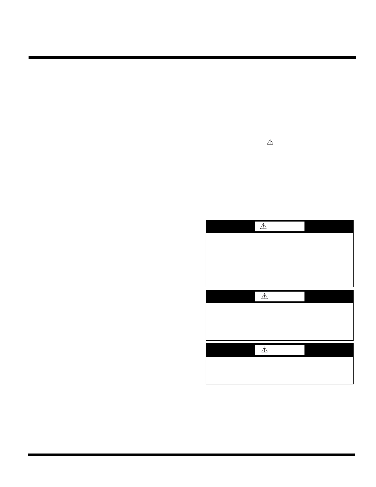
ACTUATOR
HH79AH001
OUTSIDE AIR
TEMPERATURE
SENSOR
(IN OPERATING
POSITION)
BAROMETRIC RELIEF
DAMPERS
Fig. 1 — EconoMi$er
ECONOMI$ER X
WIRING HARNESS
®
X Component Locations
HH79AH001 OUTSIDE AIR
TEMPERATURE SENSOR
(IN SHIPPING POSITION)
OUTSIDE
AIR DAMPER
(CRECOMZR067A01 Shown)
For 48/50LC 07-12 Instructions, see “Instructions for 48/50LC
07-12 Units Only” on page 10.
INSTALLATION
NOTE: If installing economizer on 48/50LC 07-12 units, see
“Instructions for 48/50LC 07-12 Units Only” on page 10.
1. Turn off unit power supply(s) and install lockout tag.
2. Remove the existing unit filter access panel. Raise the
panel and swing the bottom outward. The panel is now
disengaged from the track and can be removed. See Fig. 2.
Set the filter door aside for re-installation later.
FILTER ACCESS PANEL
COMPRESSOR
ACCESS PANEL
OUTDOOR-AIR OPENING AND
INDOOR COIL ACCESS PANEL
Fig. 2 — Typical Access Panel Locations
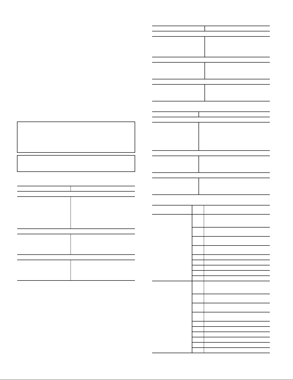
3. Remove the indoor coil access panel and discard. See
Fig. 2.
4. Slide the EconoMi$er X assembly into the rooftop unit.
See Fig. 3.
NOTE: On small and large cabinets be sure to engage the rear
EconoMi$er X flange under the tabs on the unit base in the return air chamber. See Fig. 4.
3
Page 4
®
HVAC UNIT FILTERS
INSERT
SCREW IN
ECONOMI$ER X
FLANGES
WIRING
HARNESS
ECONOMI$ER X
UNIT FILTER
RACK
UNIT BASE
ECONOMI$ER X
HOLD DOWN TAB
ECONOMI$ER X REAR FLANGE
ECONOMI$ER X
INDOOR FAN MOTOR
ACCESS PANEL
UNIT CONTROL
BOX PANEL(S)
CENTER POST
Fig. 3 — EconoMi$er
X Assembly Installed on
HVAC Unit (CRECOMZR067A01 Shown)
ROOFTOP UNIT’S
12-PIN MALE PLUG
ECONOMI$ER X
12-PIN FEMALE PLUG
(CRECOMZR067A01 and CRECOMZR069A01)
5. Ensure EconoMi$er X assembly is square (tolerance
6. Remove the red tape securing the relief dampers for ship-
7. If the EconoMi$er X assembly will be operating with an
Fig. 4 — EconoMi$er X Flange Installation
1
±
/32 inch). Screw the EconoMi$er X to the unit along
both side flanges and bottom flange. See Fig. 3.
ping purposes. Relocate the HH79AH001 dry bulb sensor from its shipping location to its operating position;
see Fig. 1.
enthalpy outside air sensor, remove the factory-installed
HH79AH001 dry bulb sensor from the front face of the
economizer (see Fig. 1) and install the accessory
enthalpy sensor HH57AC081 in the same location as the
dry bulb sensor. Connect the 2-wire gray harness with
plug from the EconoMi$er X assembly to the enthalpy
sensor. See wiring diagrams on pages 9 and 12. Refer to
“Installing Optional HH57AC081 Single Outside Air
Enthalpy Sensor” on page 13 for more details on
enthalpy settings.
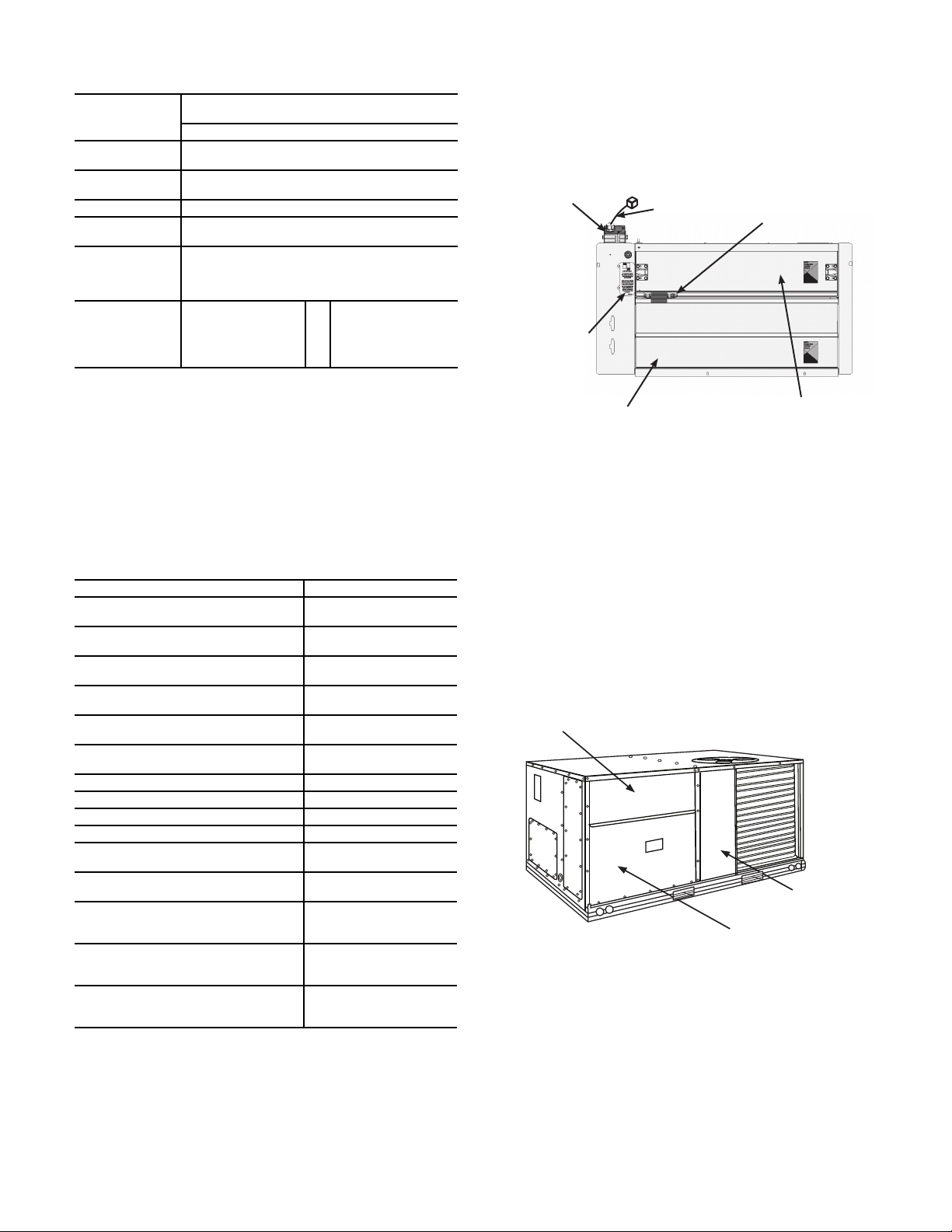
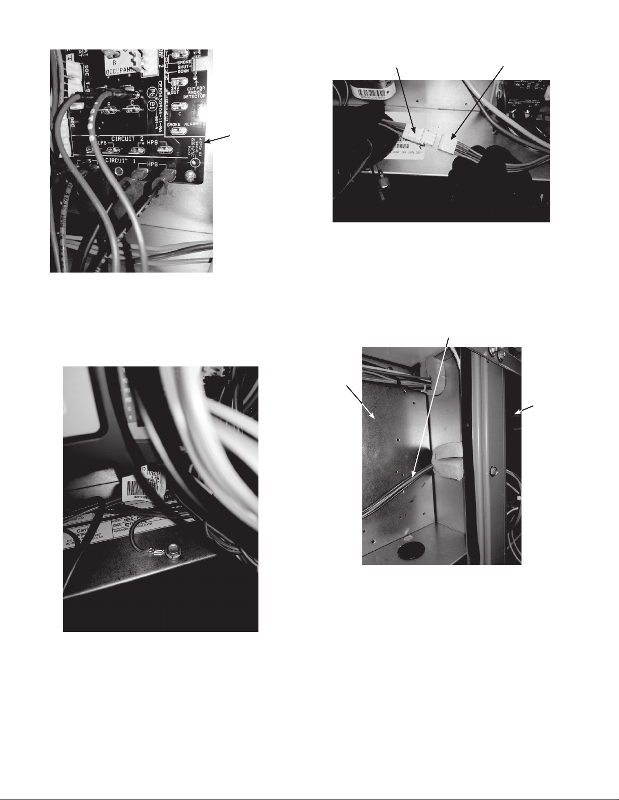
Fig. 5 — Connect EconoMi$er X Harness to Unit PL6
Economizer Harness
8. Remove and save the 12-pin jumper plug from the unit
economizer harness located in the upper left corner of the
unit. Insert the EconoMi$er X plug into the unit wiring
harness. See Fig. 5.
NOTE: The 12-pin jumper plug should be saved for future use,
in the event that the EconoMi$er X is ever removed. The jumper
plug is not needed as long as the EconoMi$er X is installed.
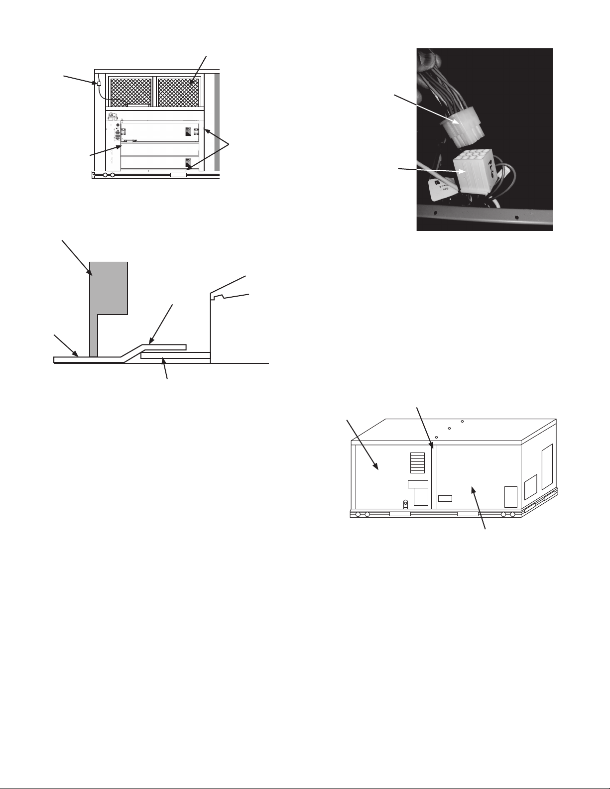
9. Remove the indoor blower access panel and the panel(s)
covering the unit control box. See Fig. 6.
Fig. 6 — Typical Indoor Fan Motor Access Panel
Locations
10. In the hardware kit provided with the EconoMi$er X
assembly is the HH63AW002 Jade controller (Honeywell W7220). The controller is attached to a mounting
bracket and the EconoMi$er X harness is attached to the
controller. Mount the controller assembly on the left side
of the unit control box. Screw bracket to the control box
through pre-punched holes in control box. See Fig. 7.
4
Page 5
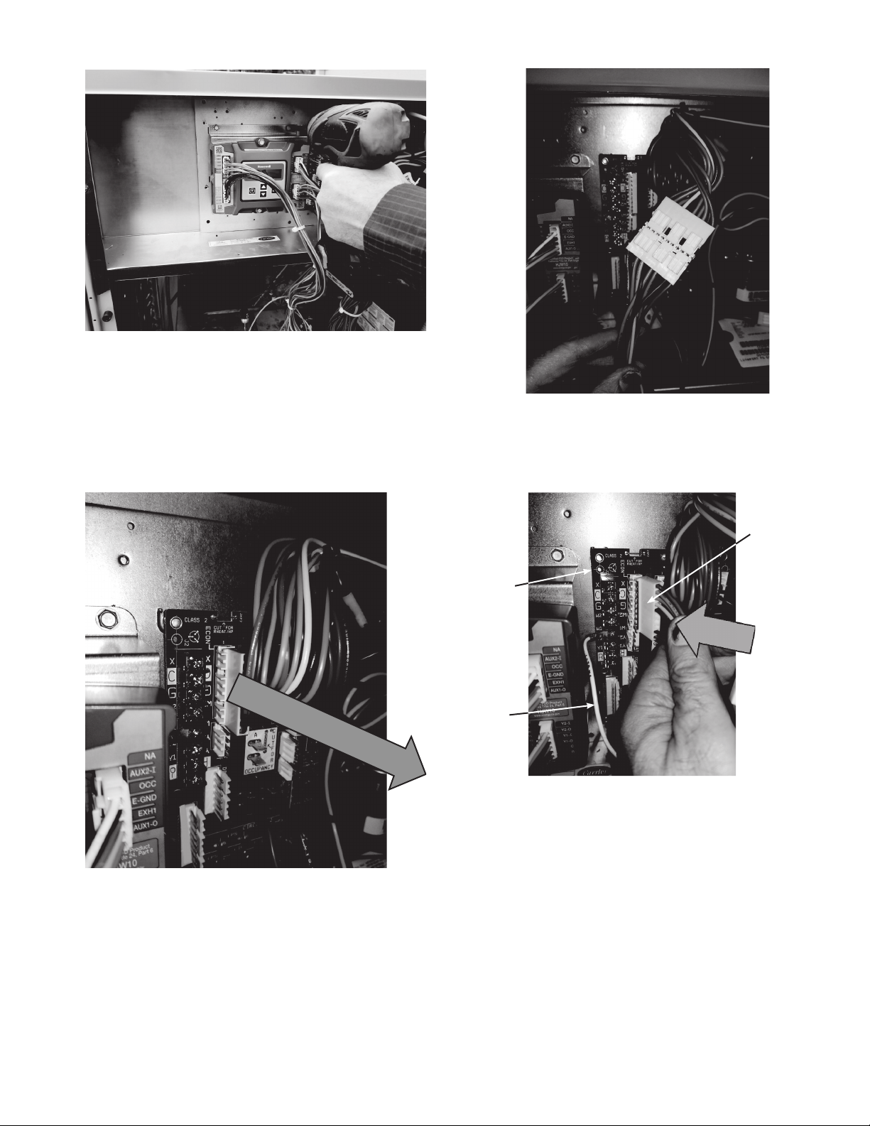
Fig. 7 — Mount Controller Assembly in Unit
CENTRAL
TE RM I NA L
BOARD
WHITE
WIRE
10-PIN
FEMALE
PLUG FROM
CONTROLLER
Control Box
(Some control box configurations may differ)
11. Unplug the 10-pin female ECON plug currently connected to the Central Terminal Board (CTB). See
Fig. 8.
Fig. 9 — Connect 10-pin Plugs Together
13. Connect the 10-pin female plug from the Jade controller
harness to ECON on the CTB. See Fig. 10 and page 9.
Fig. 10 — Connect 10-Pin Jade Plug to Central
Terminal Board
Fig. 8 — Unplug ECON plug from Central Terminal
Board (CTB)
12. Connect the 10-pin female ECON plug removed from
the CTB to the 10-pin male plug from the Jade controller harness. See Fig. 9 and page 9.
14. Connect the White wire from the Jade controller harness
to the W1 terminal on the CTB. See Fig. 10 and page 9.
15. Connect the red and brown wires from the Jade controller harness to the CTB. See Fig. 11 and page 9. The red
wire connects to “R” on the CTB, and the brown wire
connects to “C”.
5
Page 6
CENTRAL
TERMINAL
BOARD
4-PIN MALE PLUG
FROM CONTROLLER
48TMHSRSE--A20
HARNESS
Fig. 11 — Connect Red and Brown Wires to Central
Terminal Board
16. Locate the green wire with yellow stripe from the Jade
controller harness and screw it to the control box
(ground). See Fig. 12 below.
Fig. 13 — Connect 48TMHSRSE--A20 Harness to
Harness from Controller
18. Route the 4-wire 48TMHSRSE--A20 harness through
the divider between the control box and the indoor
blower section. See Fig. 14.
48TMHSRSE--A20
HARNESS
CONTROL
BOX
INDOOR
BLOWER
SECTION
Fig. 12 — Connect Ground Wire From Controller
17. Locate the 48TMHSRSE--A20 harness (with 4-pin
female plug) provided in the hardware kit with the
EconoMi$er X assembly. Connect the 48TMHSRSE-A20 harness to the 4-wire harness with a male plug from
the Jade controller harness. See Fig. 13 and page 9.
Fig. 14 — Route 48TMHSRSE--A20 Harness to
Indoor Blower Section
(Some control box configurations may differ)
19. Screw the HH79AH001 mixed air (MAT) sensor (Honeywell C7250) to the left side edge of indoor blower
through pre-punched holes; see Fig. 15. Confirm that the
screws do not interfere with blower rotation. Locate the
50HE403859 2-green wire harness shipped with the
EconoMi$er X kit. It will have a plug on one end and terminals on the other end. Connect the plug from this harness to the MAT sensor. See Fig. 15. Connect the 2 spade
terminals on the 50HE403859 harness to the orange and
brown wires from the 4-wire 48TMHSRSE--A20 Harness. See Fig.15 and page 9.
6
Page 7
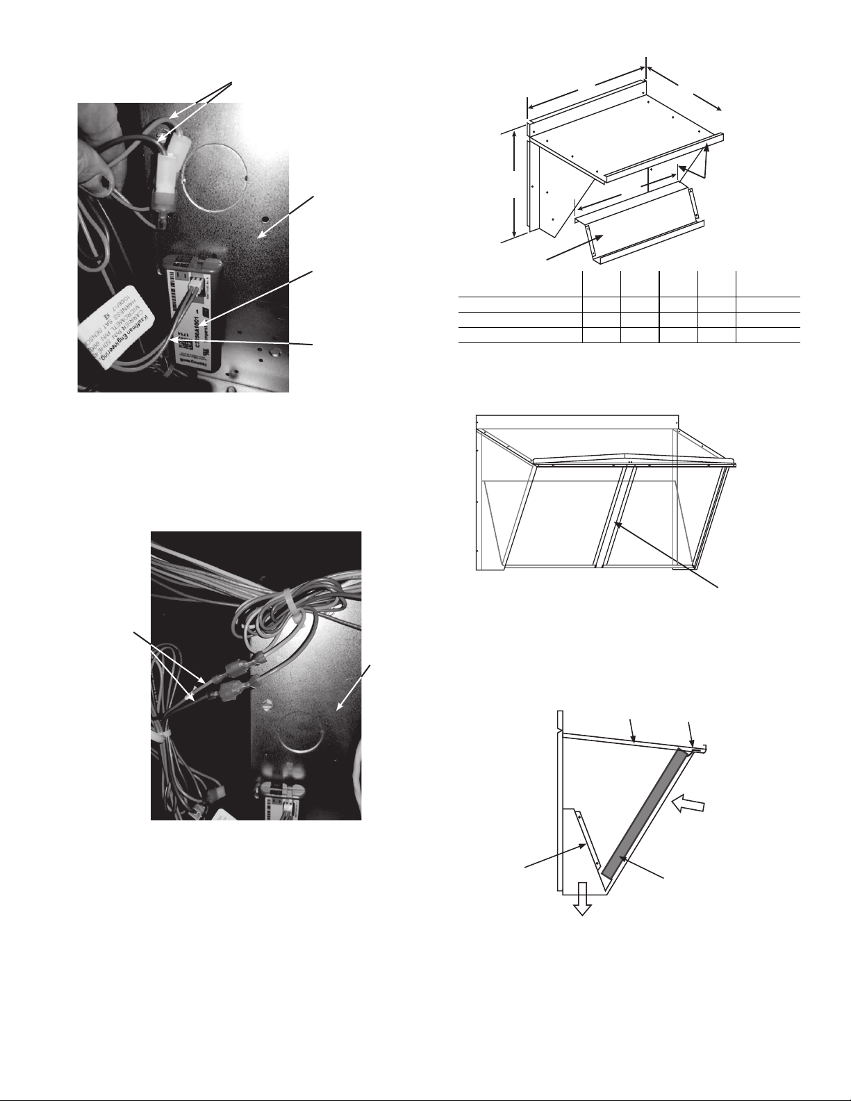
BROWN AND ORANGE WIRES FROM
48TMHSRSE--A20 HARNESS
INDOOR
BLOWER
MIXED AIR
TEMPERATURE
SENSOR
50HE403589
2-GREEN WIRE
HARNESS
INDOOR
BLOWER
PINK AND
VIOLET WIRES
FROM
48TMHSRSE--A20
HARNESS
A
HOOD TOP
FILTER CLIP
OUTSIDE AIR
CLEANABLE
ALUMINUM FILTER
BAROMETRIC
AIRFLOW
HOOD
DIVIDER
B
Fig. 15 — Mount and Connect Mixed Air Sensor
20. Connect the pink and violet wires from the 4-wire
48TMHSRSE--A20 harness to the pink and violet terminals in the wire bundle in the indoor blower section. See
Fig. 16 and page 9.
C
HOOD DIVIDER
ECONOMIZER P/N
CRECOMZR067A01 30.37 17.43 19.05 29.50 55 lb
CRECOMZR069A01 40.37 22.28 24.48 36.27 80 lb
CRECOMZR071A01 52.92 27.03 33.41 46.92 98 lb
NOTE: The CRECOMZR071A01 hood has 2 aluminum filters and a
hood filter divider that installs between the filters.
D
A
(in.)B (in.)C (in.)D (in.)
HOOD TOP AND
SIDE ASSEMBLY
SHIP WT.
(lb)
Fig. 17 — EconoMi$er® X Hood Assembly
21. If using differential return sensor or DCV sensor, install
22. Assemble the EconoMi$er X hood by screwing the hood
Fig. 16 — Connect Pink and Violet Wires in Indoor
Blower Section
it now. See installation details later in the instructions,
and the wiring diagram for further information.
divider to the hood subassembly (top and sides). See
Fig. 17. Note on the CRECOMZR071A01 there is also a
center hood filter divider; screw in place. See Fig. 18.
HOOD FILTER
DIVIDER
Fig. 18 — Filter Divider on CRECOMZR071A01 Hood
23. Install aluminum filter(s) in EconoMi$er X hood. Clips
at top of hood will hold filters in place. See Fig. 19.
Fig. 19 — Fully Assembled Hood
24. Install EconoMi$er X hood over economizer. Screw
hood in place through pre-punched holes. Reinstall the
unit’s filter access door. See Fig. 20. Re-install the
Indoor blower access panel. See Fig. 6.
7
Page 8
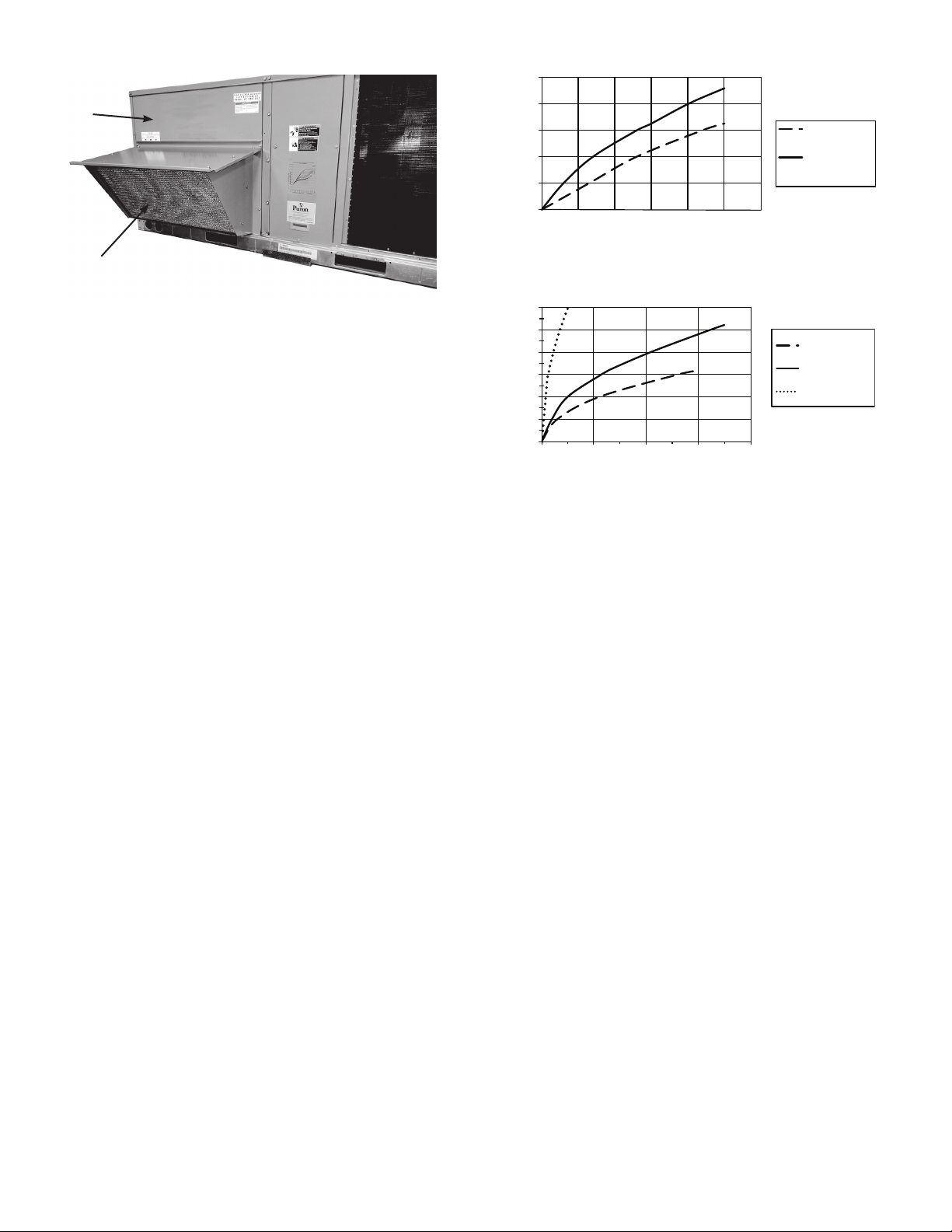
ECONOMI$ER X
HOOD
FILTER
DOOR
0
500
1000
1500
2000
2500
0 0.05 0.1 0.15 0.2 0.25 0.3
RELIEF FLOW (CFM
RETURN DUCT STATIC PRESSURE (i n. wg)
CRECOMZR067A01
CRECOMZR069A01
and
CRECOMZR071A01
0
1000
2000
3000
4000
5000
6000
00.10.20.30.4
RETURN AI R FLOW (CFM)
RETURN DUCT STATIC PRESSURE DRO P (in. wg)
CRECOMZR067A01
CRECOMZR069A01
CRECOMZR071A01
Fig. 21 — Barometric Relief Flow Capacity
Fig. 20 — Install EconoMi$er X Hood and Unit Filter
Access Door
25. After powering unit controller, program the Jade W7220
controller per the instructions to follow. See Table 8 for
summarized controller set up instructions. After all settings have been made, re-install the unit control box
panel. See Fig. 6.
Economizer performance charts are shown in Fig. 21 and
22. See base unit installation manual to make adjustments to
meet building ventilation requirements. See Fig. 23 for typical EconoMi$er X wiring diagram.
Fig. 22 — Return Air Pressure Drop
8
Page 9

Mixed Air Sensor
Field Mount on
Indoor Blower
1
HH79AH001
HONEYWELL C7250
Dry Bulb
Outside Air
Sensor
12-Pin Female
Plug from Economizer
Economizer
Harness
In Unit
50HE403859
Harness
GRN
GRN
WHT
BLK
GRN
BLU
BLK
GRA
GRA
GRA
GRA
PNK
PNK
BLU
BLK
PNK
GRA
GRA
GRA
RED
PNK
ORG
BRN
YEL
VIO
VIO
VIO
ORG
ORG
BRN
BRN
GRN
GRN
6
7
2
3
10
11
5
1
12
9
4
8
RED
ORG
1
2
3
4
RED
Economizer
Actuator
1
2
3
4
HH57AC081
1
2
1
Enthalpy Outside
Air Sensor
To Optional
Power Exhaust
PL6
Plug
12-Pin Male
Plug in Unit
48TMHSRSE--A20
Harness with
4-Pin Female Plug
4-Pin Male
Plug
10-Pin Male
Plug
PNK
BLU
BLK
GRA
GRA
RED
“R” ON CTB
ORG
BRN
YEL
“C” ON CTB
BLU
BLK
GRN / YEL
WHT
BLU
GRA
ORG
YEL
BLK
BRN
RED
VIO
1
1
2
2
334
10
645913827
1
2
3
4
5
6
7
8
9
10
4
9
3
8
10
2
6
7
5
1
4
10-Pin Female
Plug Disconnected
from CTB
CO2
(Optional)
Ground
“W1” on CTB
W7220 JADE
Controller.
Field Mounted in
Unit Control Box
MAT
MAT
OAT
OAT
ACT 24V
ACT COM
S-BUS
S-BUS
EXH1
IAQ COM
ACT 2-10
AUX1 OUT
IAQ 2-10
E-GRD
AUX2 IN
Y1 IN
Y1 OUT
Y2 OUT
Y2 IN
OCC
C
R
10-Pin Female
Plug Connects to
ECON on
Central Terminal
Board
BRN
YEL
Either the OAT or the Enthalpy
Sensor can be used but not both.
Remove OAT if Enthalpy’s used.
Refer to Figures 33 and 34 for Remote
Fault Detection and Diagnostic Monitoring.
LEGEND
3
Refer to Figure 31 for wiring optional
Differential Return Air Sensor kit.
ECONOMIZER RETURN CHAMBER INDOOR BLOWER SECTION
UNIT CONTROL BOX COMPARTMENT
DA
RA
OA
123
S-Bus
Temp & Humidity
HH57AC081
S-Bus
CTB: Central Terminal Board
MAT: Mixed Air Temperature Sensor
OAT: Outside Air Temperature Sensor
HH79AH001
HONEYWELL C7250
Fig. 23 — Typical EconoMi$er X Wiring Diagram for 1 or 2 Speed Units (Not for 48/50LC 07-12 Units)
9
Page 10

Instructions for 48/50LC 07-12 Units Only
IMPORTANT: This section is for economizer installation instructions on 48/50LC 07-12 units only.
1. Step LC1. Follow steps 1 through 10 earlier in these
instructions.
2. Step LC2. The 48/50LC 07-12 units require different
wiring than is factory-attached to the W7220 Jade controller. Disconnect the complete wiring harness factoryattached to the W7220 Jade controller, as shown below
in Fig. 24. This harness can be discarded.
NOTE: The 4-wire 48TMHSRSE--A20 harness provided with
the economizer will also NOT be used on the 48/50LC07-12
units; see Fig. 25.
Fig. 24 — Remove Complete Harness Factory
Attached to W7220 Controller
Fig. 25 — 48TMHSRSE--A20 Not Used on
48/50LC 07-12 Units
3. Step LC3. The 48/50LC 07-12 units that do not have a
factory-installed economizer will have a new Jade
W7220 controller wiring harness shipped in the control
box section of the HVAC unit. This harness, Carrier part
number 48LCHSRADH--A00, is shown below in Fig. 26
and 27.
Fig. 26 — 48LCHSRADH--A00 W7220 Controller Harness Shipped With 48/50LC 07-12 Units
10
Page 11

Fig. 27 — Photo of 48LCHSRADH--A00 W7220
Controller Harness Shipped with 48/50LC 07-12
Units
4. Step LC4. The connectors on the right side of Fig. 26 on
the 48LCHSRADH--A00 harness attach to the Jade
W7220 controller installed in the unit control box. See
Fig. 26 and 28. 48LCHSRADH--A00 harness connectors
are labeled to easily identify the plug-in location on the
controller.
5. Step LC5. Locate the Compressor Staging Control (CSC)
board in the HVAC unit. When a field-installed economizer is used the J5 jumper on the CSC must be
removed. Remove the J5 jumper. See Fig. 28.
6. Step LC6. The connectors on the left side of Fig. 26 on
the 48LCHSRADH--A00 harness attach to the unit’s
CSC board. Connect J3 and J5 plugs to the CSC board.
7. Step LC7. Screw the green wire with yellow stripe in the
48LCHSRADH--A00 harness to the control box
(ground). See Fig. 12 and 28.
8. Step LC8. Mount the provided HH79AH001 mixed air
temperature (MAT) sensor (C7250) to the indoor blower.
Confirm that the screws do not interfere with blower
rotation. See Fig. 15. Locate the 50HE403859 2-green
wire harness shipped with the EconoMi$er X kit. It will
have a plug on one end and terminals on the other end.
Connect the plug from this harness to the MAT sensor.
See Fig. 15. Connect the (2) spade terminals on the
50HE403859 harness to orange and brown wires in the
indoor blower section wire bundle.
9. Step LC9. Follow steps 21 through 25 earlier in these
instructions.
11
Page 12

NOTES:
1. Harness shown in bold is 48LCHSRADH--A00 harness, which is shipped in the control box
of 48/50LC 07-12 units and must be field connected to the W7220 controller provided with
the economizer.
2. Harness attached to the W7220 controller from the Carrier factory is removed and not used
with 48/50LC 07-12 units.
Fig. 28 — Typical Wiring Diagram For 48/50LC 07-12 Units
12
Page 13

Installing Optional HH57AC081 Single Outside
ECONOMIZING
AVAILABLE
NOT AVAILABLE
ENTHALPY
RA HUM (%RH)
RA TEMP
TEMPERATURE
ABSOLUTE HUMIDITY
ES5
ES4
ES3
ES2 ES1
HL
P1
(T,RH)
P2 (T,RH)
SINGLE ENTHALPY
DUAL ENTHALPY
HIGH LIMIT
DARAOA
123
S-Bus
Temp & Humidity
HH57AC081
4-1/4 (108)
2-3/4 (70)
2-1/64 (55)
S-Bus
NOTE: Dimensions are in. (mm).
Air Enthalpy Sensor
When using the HH57AC081 (Honeywell C7400S) enthalpy sensor (Fig. 30) for outside air changeover, the existing
HH79AH001 (Honeywell C7250) dry bulb sensor must be removed. The enthalpy sensor will be mounted in the same location as the dry bulb sensor; see Fig. 1. When the enthalpy sensor’s OA temperature, enthalpy, and dew point are below the
respective setpoints, the outside air can be used for free-cooling. When any of these is above the setpoint, free-cooling will
not be available. Figure 29 shows the enthalpy boundaries in
the W7220 Jade controller. There are 5 enthalpy boundaries
(setpoints ES1 through ES5), which are defined by dry bulb
temperature, enthalpy, and dew point. ES3 is the default setting. Table 7 shows the High Limit Curves for each setting. Important: to use the HH57AC081 sensor for outside air sensor,
the dip switches on the sensor must be set to OFF-OFF-OFF.
See Table 8.
The 2 gray wires with a plug from the EconoMi$er X harness in the return chamber plug directly into the HH57AC081
enthalpy sensor. See Fig. 23 and 28 for wiring.
Fig. 29 — Enthalpy Curve Boundaries
Table 7 — Single Enthalpy and Dual Enthalpy High Limit Curves
ENTHALPY
CURVE
TEMP. DRY
BULB (F)
TEMP.
DEWPOINT (F)
ENTHALPY
(btu/lb/da)
TEMP. (F)
ES1 80 60 28.0 80 36.8 66.3 80.1
ES2 75 57 26.0 75 39.6 63.3 80.0
ES3 70 54 24.0 70 42.3 59.7 81.4
ES4 65 51 22.0 65 44.8 55.7 84.2
ES5 60 48 20.0 60 46.9 51.3 88.5
HL 86 66 32.4 86 38.9 72.4 80.3
POINT P1 POINT P2
HUMIDITY
(%RH)
TEMP. (F)
Table 8 — HH57AC081 Sensor Dip Switch Settings
USE
LEGEND
DA — Discharge Air (not used on EconoMi$er X)
RA — Return Air
OA — Outside Air
Default Setting = OFF-OFF-OFF
DIP SWITCH POSITIONS FOR SWITCHES 1, 2, AND 3
123
DA OFF ON OFF
RA ON OFF OFF
OA OFF OFF OFF
HUMIDITY
(%RH)
Fig. 30 — HH57AC081 Dimensional, Connection and
Switching Information
13
Page 14

Installing Differential Return Air Sensor
12-PIN FEMALE
PLUG FROM ECONOMIZER
BLU
BLK
GRA GRA GRA
GRA GRA
GRA
GRA
PNK
VIO
6
7
2
3
10
11
5
1
12
9
4
8
RED
ORG
PL6
PLUG
12-PIN MALE
PLUG IN UNIT
BRN
YEL
*HH57AC081
DIFFERENTIAL RETURN
SENSOR. FIELD MOUNTED
IN RETURN DUCT
WIRING
HARNESS*
*PROVIDED IN
CRDIFRASN01A00 Kit
The CRDIFRASN01A00 differential return sensor kit
must be field mounted in the system’s return duct work. The
kit includes a wiring harness, that connects the EconoMi$er
X harness in the return chamber of the unit, to the provided
HH57AC081 sensor. Wire per Fig. 31.
In addition to using the HH57AC081 (Honeywell
C7400S) sensor (Fig. 30) for a single enthalpy sensor, it can
also be used as a differential return enthalpy or dry bulb sensor. Figure 29 shows the dual enthalpy boundaries in the
W7220 Jade controller. With dual enthalpy the high limit
boundary is ES1 when there are no stages of mechanical
cooling energized and HL (high limit) when a compressor
stage is energized. Table 7 shows the High Limit Curves for
each setting. Important: to use the HH57AC081 sensor for
differential return air, the dipswitches on the sensor must be
set to ON-OFF-OFF. See Table 8.
When using the CRDIFRASN01A00 differential return
enthalpy or dry bulb temperature option, see Table 9 for California Title 24 setting requirements by region.
Table 9 — California Title 24 Regional High Limit Dry
Bulb Temperature Settings
REQUIRED HIGH LIMIT
DEVICE TYPE*
FIXED DRY BULB
DIFFERENTIAL DRY
BULB
FIXED ENTHALPY† +
FIXED DRY BULB
* Only the high limit control devices listed are allowed to be used and
at the setpoints listed. Others such as Dew Point, Fixed Enthalpy,
Electronic Enthalpy, and Differential Enthalpy Controls may not be
used in any climate zone for compliance with Section 140.4(e)1
unless approval for use is provided by the Energy Commission
Executive Director.
† At altitudes substantially different than sea level, the Fixed Enthalpy
limit value shall be set to the enthalpy value at 75°F and 50% relative humidity. As an example, at approximately 6,000 foot elevation,
the fixed enthalpy limit is approximately 30.7 Btu/lb.
CLIMATE
ZONES
1, 3, 5, 11-16 OAT exceeds 75°F
2, 4, 10 OAT exceeds 73°F
6, 8, 9 OAT exceeds 71°F
7 OAT exceeds 69°F
1, 3, 5, 11-16 OAT exceeds RA Temp.
2, 4, 10 OAT exceeds -2°F
6, 8, 9 OAT exceeds -4°F
7 OAT exceeds -4°F
ALL
(ECONOMIZER OFF
WHEN):
DESCRIPTION
OAT exceeds 28 Btu/lb of dry
air or OAT exceeds 75°F
Demand Controlled Ventilation (DCV)
Refer to EconoMi$er X wiring diagrams Fig. 23 and 28 and
DCV instructions if demand control ventilation (CO
used. CO2 sensor will wire into the blue and black connections
at the Jade controller as shown in Fig. 23, 28, and 32. If a fieldinstalled CO
sensor is connected to the EconoMi$er X con-
2
troller, a demand-controlled ventilation strategy will operate
automatically. As the CO
level in the space increases above
2
the setpoint (on the EconoMi$er X controller), the minimum
position of the dampers will be increased proportionally, until
the Maximum Ventilation setting is reached. As the space CO
level decreases because of the increase in fresh air, the outdoor
damper will follow the higher demand condition from the DCV
mode or from the free cooling mode.
sensor) is
2
2
Fig. 31 — Wiring Differential Return Air Sensor
California’s Title 24 High Temperature Limit Settings
California’s Title 24 code requires a high temperature limit
setting for all dry bulb outside air economizer changeover.
The temperatures vary by the region within California. See
Table 9 for high limit settings.
14
BLUE WIRE
IAQ COM
Fig. 32 — CO
BLACK WIRE
IAQ 2-10 VDC
Wiring Connections to Jade
2
Controller
Page 15

Remote (Downstairs) Monitoring of Control-
CR
AUX2-1
OCC
E-GND
EXH1
AUX1-0
Y2-I
Y2-O
Y1-I
Y1-O
C
R
W7220 JADE
ECONOMIZER
U1
U1
R
Rc
C
A-L/A
FURNACE, AIR HANDLER,
OR RTU
TH8321R OR
TH8321WF
SUB-BASE
ler’s Fault Detection and Diagnostics
Many codes including IECC, Title 24, and ASHRAE 90.1
require that the economizer’s faults be accessible by operating or service personal, or annunciated locally on zone thermostat. To setup remote monitoring on the controller, under
SYSTEM SETUP, AUX1-OUT must be set to SYS.
The latest versions of Honeywell’s TH8321WF or
TH8321R thermostats are options for meeting this requirement. Figure 33 shows an example of the thermostat wiring to
the Jade controller. Follow instructions provided with Honeywell thermostat.
Another option that is acceptable to some codes is an annunciator light visible by service personnel. See Fig. 34 for
typical wiring to the Jade controller. Refer to codes for proper
labeling of light.
W7220 Economizer Controller Module
Fig. 33 — Thermostat Wired For Remote FDD
MAT
MAT
OAT
OAT
IAQ (2-10V)
IAQ COM
IAQ 24V
ACT (2-10V)
ACT COM
ACT 24V
JADE Setting: Under the “System Setup” menu, set AUX1-OUT to
“SYS” which will close JADE relay on fault detection
Fig. 34 — Annunciator Light Wired for Remote FDD
AUC2-1
OCC
E-GND
EXH1
AUX1-0
Y21
Y2O
Y1I
Y1O
=CR
TO “AUX1-0” TERMINAL
TO “C” TERMINAL
Annunciator Light*
Examples of annunciator lights
would include these Grainger lights:
- Item #20C841
- Item #20C846
15
Page 16

GENERAL JADE W7220 CONTROLLER AND
SENSOR INFORMATION
W7220 Economizer
The economizer controller used on electromechanical
units is the Honeywell W7220 which is to be located in the
RTU base unit’s control box. See Fig. 35 for button descriptions of the W7220 controller. The W7220 controller provides the following:
• 2-line LCD interface screen for setup, configuration, and
troubleshooting.
• On-board fault detection and diagnostics
• Sensor failure loss of communications identification
• Automatic sensor detection
• Capabilities for use with multiple-speed indoor fan systems
NOTE: When values are displayed, pressing and holding the ▲
or ▼ button causes the display to automatically increment.
7. Press the (Enter) button to accept the displayed value
and store it in nonvolatile RAM.
8. “CHANGE STORED” displays.
9. Press the (Enter) button to return to the current menu
parameter.
10. Press the (Menu Up/Exit) button to return to the previous menu.
Menu Structure
Table 11 illustrates the complete hierarchy of menus and
parameters for the EconoMi$er X system.
The menus in display order are:
•STATUS
•SETPOINTS
• SYSTEM SETUP
• ADVANCED SETUP
• CHECKOUT
•ALARMS
IMPORTANT: The default setting on the W7220 controller is for a Fan Type” with 2 speed. For a 1 (single)
speed unit, the setting under SYSTEM SETUP > FAN
TYPE must be changed to 1 speed.
Fig. 35 — W7220 Controller
User Interface
The user interface consists of a LCD display and a 4-button
keypad on the front of the economizer controller.
Keypad
The four navigation buttons (see Fig. 35) are used to scroll
through the menus and menu items, select menu items, and
change parameter and configuration settings.
Using the Keypad with Menus
To use the keypad when working with menus:
•Press ▲ (Up arrow) button to move to the previous menu.
•Press the ▼ (Down arrow) button to move to the next menu.
• Press the (Enter) button to display the first item in
the currently displayed menu.
• Press the (Menu Up/Exit) button to exit a menu’s
item and return to the list of menus.
Using the Keypad with Settings and Parameters
To use the keypad when working with Setpoints, System
Setup Advanced Settings, Checkout Tests and Alarms:
1. Navigate to the desire menu.
2. Press the (Enter) button to display the first item in
the currently displayed menu.
3. Use the ▲ and ▼ buttons to scroll to the desired parameter.
4. Press the (Enter) button to display the value of the
currently displayed item.
5. Press the ▲ button to increase (change) the displayed
parameter value.
6. Press the ▼ button to decrease (change) the displayed
parameter value.
PROGRAMMING JADE W7220 CONTROLLER
The next several pages detail the different status displays,
setpoints, setup, and alarms available on the controller. This
list below and Table 10 summarizes the inputs required for a
standard application with a single outside air sensor.
NOTE: Default settings already set in the Jade controller may be
used instead of setting the SETPOINTS; see default settings below. See Table 10 for summarized standard settings or for more
detail see Table 11 — Menu Structure.
Setpoints
• MAT SET: this sets the mixed air temperature (MAT) setting. The controller has a default of 53°F, but the range is
anywhere from 38 to 70°F.
• LOW T LOCK: This setting locks out the compressor (or
mechanical cooling) at a given temperature. The default
is 32°F, but the controller’s range is from -45 to 80°F.
• DRYBULB SET: for an economizer with a dry bulb outside air sensor, set the DRYBULB SET. The default setting is 63°F but the controller’s range is 48 to 80°F.
• ENTH CURVE: for a single enthalpy outside air sensor instead of a dry bulb, set the ENTH CURVE setting. There
are 5 setting options: ES1 through ES5. Check the economizer literature for the limits for each of these settings.
ES3 is the default setting.
• MIN POS: The minimum position allows for ventilation
even when not in the free-cooling mode. A single speed
unit has only one minimum position setting. The default is
4.4 volts, but the range is 2-10Vdc.
• MIN POS H and MIN POS L: A 2 speed unit has 2 minimum position settings that show up on the menu. The first
is MIN POS H (for high speed) which has a default of 4.4
volts. The second is MIN POS L (for low speed), which
has a default of 6.0. Note that MIN POS H and MIN POS
L are only displayed if under SYSTEM SETUP: AUX2 IN
is set to “W1” and FAN TYPE is set to 2 speed.
16
Page 17

System Setup
• INSTALL: Use to set the current date. Use the keypad
buttons to scroll to the correct date.
• EQUIPMENT: Always set to CONV even if the unit is
a heat pump.
• AUX2 IN: Always set to W.
Table 10 — Standard Jade W7220 Controller Configuration for 1 or 2 Speed Unit
• FAN TYPE: Set for either single or 2 speed. The default
is 2 speed. (See Note 3 below.)
• AUX1 OUT: If remote Fault Detection and Diagnostic
(FDD) monitoring is required select SYS.
• OCC: occupancy, always set to INPUT
CONTROLLER MENU
SETPOINTS
SYSTEM
SETUP
NOTES:
1. For 2 speed unit, under SYSTEM SETUP: EQUIPMENT=
CONV, AUX2 I = W, and FAN TYPE = 2 SPEED
2. More sophisticated controller setups, including for DCV or
power exhaust, are available by referring to Table 11 options
ITEM
MAT SET 53°F 38° to 70°F 53°F 38° to 70°F
LOW T LOCK 32°F -45° to 80°F 32°F -45° to 80°F
DRYBLB SET 63°F 48° to 80°F 63°F 48° to 80°F Only displayed if using single DB OA sensor
ENTH CURVE ES3 ES1 to ES5 ES3 ES1 to ES5
MIN POS 4.4 Vdc 2 to 10 Vdc Only displayed if set up for single speed unit
MIN POS H NA NA 4.4 Vdc 2 to 10 Vdc Only displayed if set up for 2 speed unit
MIN POS L NA NA 6.0 Vdc 2 to 10 Vdc Only displayed if set up for 2 speed unit
INSTALL 1/1/2010 Current date 1/1/2010 Current date
EQUIPMENT CONV CONV CONV CONV Always set to CONV, even on HP units
AUX2 I WWWWAlways set to W
FAN TYPE 2 speed 1 speed 2 speed 2 speed See Note 3
AUX1 OUT NONE SYS NONE SYS Set to SYS for remote FDD monitoring
OCC INPUT INPUT INPUT INPUT Always set to INPUT
FOR SINGLE SPEED UNIT FOR 2 SPEED UNITS
DEFAULT SET TO: DEFAULT SET TO:
NOTE
Only displayed if using a single enthalpy OA
sensor
3. Note 3: Fan speed options are:
a. 1 speed
b. 2 speed
c. 2 speed: 1 heat, 1 cool (for future use)
d. 3 speed: 1 heat, 2 cool (for future use; do not use 3 speed
NA = Not applicable
setting for LC units)
17
Page 18

Table 11 — Menu Structure*
MENU PARAMETER
ECONO AVAIL NO YES/NO
ECONOMIZING NO YES/NO
OCCUPIED NO YES/NO
HEAT PUMP N/A**
COOL Y1—IN OFF ON/OFF
COOL Y1—OUT OFF ON/OFF
COOL Y2—IN OFF ON/OFF
COOL Y2—OUT OFF ON/OFF
MA TEMP nn°F (or °C)
DA TEMP nn°F (or °C)
STATUS
OA TEMP nn°F (or °C)
OA HUM nn% 0 to 100%
RA TEMP nn°F (or °C)
RA HUM nn% 0 to 100%
IN CO2 _ _ _ ppm 0 to 2000 ppm
DCV STATUS N/A ON/OFF
DAMPER OUT 2.0v 2.0 TO 10.0v
ACT POS nn% 0 to 100%
ACT COUNT N/A 1 to 65535
ACTUATOR N/A
EXH1 OUT OFF ON/OFF
EXH2 OUT OFF ON/OFF
PARAMETER
DEFAULT
VALUE
PARAMETER
RANGE AND
INCREMENT†
COOL
HEAT
0 to 140°F
(–18 to 60°C)
0 to 140°F
(–18 to 60°C)
–40 to 140°F
(–40 to 60°C)
0 to 140°F
(–18 to 60°C)
OK/Alarm
(on Alarm menu)
NOTES
ECONOMIZING AVAILABLE
YES = economizing available; the system can use outside air for free cooling
when required
ECONOMIZING ACTIVE
YES = Outside air being used for first stage cooling.
NO = Economizing not active
OCCUPIED
YES = OCC signal received from space thermostat or unitary controller.
YES = 24 Vac on terminal OCC.
NO = 0 Vac on terminal OCC
HEAT PUMP MODE
(Not available on 2 Speed configuration)
FIRST STAGE COOLING DEMAND (Y1—IN)
Y1—I signal from space thermostat or unitary controller for Cooling Stage 1.
ON = 24 Vac on terminal Y1—I
OFF = 0 Vac on terminal Y1—I
FIRST STAGE COOLING RELAY OUTPUT
ON = 24 Vac on terminal Y1—O; Stage 1 mechanical cooling called on
OFF = 0 Vac on terminal Y1—O; no mechanical cooling
SECOND STAGE COOLING DEMAND (Y2—IN)
Y2—I signal from space thermostat or unitary controller for Cooling Stage 2.
ON = 24 Vac on terminal Y2—I
OFF = 0 Vac on terminal Y2—I
SECOND STAGE COOLING RELAY OUTPUT
ON = 24 Vac on terminal Y2—O; Stage 2 mechanical cooling called on
OFF = 0 Vac on terminal Y2—O; no Stage 2 mechanical cooling
MIXED AIR TEMPERATURE, Cooling Mode
Displays value of measured mixed/cooled air from MAT sensor in fan
section.
Displays_____ if not connected, short or out-of-range.
DISCHARGE AIR TEMPERATURE, after Heating section
(Accessory sensor required)
Displays when Discharge Air sensor is connected and displays measured
discharge temperature.
Displays_____ if sensor sends invalid value, if not connected, short or outof-range.
OUTSIDE AIR TEMPERATURE
Displays measured value of outdoor air temperature.
Displays_____ if sensor sends invalid value, if not connected, short or outof-range.
OUTSIDE AIR RELATIVE HUMIDITY
Displays measured value of outdoor humidity from accessory OA enthalpy
sensor.
RETURN AIR TEMPERATURE
(Accessory sensor required)
Displays measured value of return air temperature from return air sensor.
RETURN AIR RELATIVE HUMIDITY
(Accessory enthalpy sensor required)
Displays measured value of return air humidity from return air sensor.
SPACE/RETURN AIR CO2
(
sensor required, accessory or factory option)
CO
2
Displays value of measured
Invalid if not connected, short or out-of-range
DEMAND CONTROLLED VENTILATION STATUS
(
sensor required, accessory or factory option)
CO
2
Displays ON if IN CO2 value above setpoint DCV SET and OFF if below
CO
from
2
CO
sensor.
2
setpoint DCV SET.
Displays voltage output to the damper actuator.
0% = OA Damper fully closed
100%= OA Damper full open
Displays actual position of outdoor air damper actuator
2.0V = OA Damper fully.closed
10.0V = OA Damper full open
Displays number of times actuator has cycled.
1 Cycle equals accrued 180° of actuator movement in any direction
Displays Error if voltage or torque is below actuator range
EXHAUST STAGE 1 RELAY OUTPUT
Output of EXH1 terminal:
ON = relay closed
OFF = relay open
EXHAUST STAGE 2 RELAY OUTPUT
Output of AUX terminal; displays only if AUX = EXH2
ON = relay closed
OFF = relay open
18
Page 19

Table 11 — Menu Structure*(cont)
MENU PARAMETER
ERV OFF ON/OFF
STATUS
(cont)
SETPOINTS
MECH COOL ON 0 0, 1, or 2 Displays stage of mechanical cooling that is active.
FAN SPEED N/A LOW or HIGH
W (HEAT ON) N/A ON/OFF
MAT SET
LOW T LOCK
DRYBLB SET
DRYBLB DIF 0°F
ENTH CURVE ES3
DCV SET 1100 ppm
MIN POS 4.4 V 2 to 10 Vdc
MIN POS L 6.0 V 2 to 10 Vdc
MIN POS M 5.4V 2 to 10 Vdc
MIN POS H 4.4 V 2 to 10 Vdc
VENTMAX L 6.0 V 2 to 10 Vdc
VENTMAX M 5.4V 2 to 10 Vdc
VENTMAX H 4.4 V 2 to 10 Vdc
VENTMIN L 3.7 V 2 to 10 Vdc
VENTMIN M 3.4V 2 to 10 Vdc
VENTMIN H 2.8 V 2 to 10 Vdc
ERV OAT SP
EXH1 SET 50% 0 to 100%
EXH1 L SET 65%
PARAMETER
DEFAULT
VALUE
53°F
(12°C)
32°F
(0°C)
63°F
(17°C)
32°F
(0°C)
PARAMETER
RANGE AND
INCREMENT†
38 to 70°F;
(3 to 18°C)
increment by 1
–45 to 80°F;
(–43 to 27°C)
increment by 1
48 to 80°F
(9 to 27°C)
increment by 1
0° to 6°F
increment by 2
ES1, ES2, ES3,
ES4, or ES5
500 to 2000 ppm;
increment by 100
0 to 50°F;
(–18 to 10°C)
increment by 1
0 to 100%;
Increment by 1
NOTES
ENERGY RECOVERY UNIT RELAY OUTPUT
Output of AUX terminal; displays only if AUX = ERV
ON = relay closed
OFF = relay open
SUPPLY FAN SPEED
Displays speed setting of fan on a 2-speed fan unit.
HEAT DEMAND STATUS
Displays status of heat demand on a 2-speed fan unit.
MIXED AIR SETPOINT
Setpoint determines where the economizer will modulate the OA damper to
maintain the mixed air temperature.
COMPRESSOR LOW TEMPERATURE LOCKOUT
Setpoint determines outdoor temperature when the mechanical cooling
cannot be turned on.
OA DRY BULB TEMPERATURE CHANGEOVER SETPOINT
Setpoint determines where the economizer will assume outdoor air
temperature is good for free cooling; e.g.: at 63°F (17°C), unit will economize
at 62°F (16.7°C) and below and not economize at 64°F (17.8°C) and above.
There is a 2°F (1.1°C) deadband.
DRYBULB SET is only displayed if the economizer has a single dry bulb
sensor
DRYBULB DIFFERENTIAL will only show if using dual drybulb, i.e., when an
outdoor air temperature sensor C7250 is attached to OAT terminals, and a
C7400S sensor is wired to S-Bus and configured for RAT (return air). Free
cooling will be assumed whenever OA Temp is at or below RAT minus this
drybulb setting.
ENTHALPY CHANGEOVER CURVE
(Requires enthalpy sensor option)
Enthalpy boundary “curves” for economizing using single enthalpy.
DEMAND CONTROLLED VENTILATION SETPOINT
Displays only if
Ventilation of space. Above the setpoint, the OA dampers will modulate
open to bring in additional OA to maintain a space ppm level below the
setpoint.
VENTILATION MINIMUM POSITION. Only displays if controller is set for
single speed unit under FAN TYPE, and if DCV is NOT used.
VENTILATION MINIMUM POSITION AT LOW SPEED. Only displays if unit is
set for 2 or 3 speed and CO2 is not used. IF using 2 speed with 1 heat and 1
cool then set for HEATING ventilation. If using 3 speed with 1 heat and 2 cool
then set for LOW SPEED COOLING ventilation.
VENTILATION MINIMUM POSITION AT MEDIUM SPEED. Only displays if unit
is set for 3 speed with 1 heat and 2 cool, and CO2 is not used. Set for HEATING
ventilation.
VENTILATION MINIMUM POSITION AT HIGH SPEED. Only displays if unit is
set for 2 or 3 speed and CO2 is not used. IF using 2 speed with 1 heat and 1
cool then set for COOLING ventilation. If using 3 speed with 1 heat and 2 cool
then set for HIGH SPEED COOLING ventilation.
DCV MAXIMUM DAMPER POSITION AT LOW SPEED. Only displays if unit is
set for 2 speed or 3 speed with 1 heat and 2 cool. IF using 2 speed with 1 heat
and 1 cool then set for HEATING ventilation. If using 3 speed with 1 heat and 2
cool then set for LOW SPEED COOLING.
DCV MAXIMUM DAMPER POSITION AT MEDIUM SPEED. Only displays if
unit is set for 3 speed with 1 heat and 2 cool. Set for HEATING ventilation.
DCV MAXIMUM DAMPER POSITION AT HIGH SPEED. Only displays if unit is
set for 2 speed or 3 speed with 1 heat and 2 cool. IF using 2 speed with 1 heat
and 1 cool then set for COOLING ventilation. If using 3 speed with 1 heat and 2
cool then set for HIGH SPEED COOLING ventilation.
DCV MINIMUM DAMPER POSITION AT LOW SPEED. Only displays if unit is
set for 2 speed or 3 speed with 1 heat and 2 cool. IF using 2 speed with 1 heat
and 1 cool then set for HEATING ventilation. If using 3 speed with 1 heat and 2
cool then set for LOW SPEED COOLING.
DCV MINIMUM DAMPER POSITION AT MEDIUM SPEED. Only displays if
unit is set for 3 speed with 1 heat and 2 cool. Set for HEATING ventilation.
DCV MINIMUM DAMPER POSITION AT HIGH SPEED. Only displays if unit is
set for 2 speed or 3 speed with 1 heat and 2 cool. IF using 2 speed with 1 heat
and 1 cool then set for COOLING ventilation. If using 3 speed with 1 heat and 2
cool then set for HIGH SPEED COOLING ventilation.
ENERGY RECOVERY VENTILATION UNIT OUTDOOR AIR
TEMPERATURE SETPOINT
Only displayed when AUX1 O = ERV
Exhaust fan set point for single speed units. Based on OA Damper position
to activate power exhaust.
EXHAUST FAN SETPOINT AT LOW SPEED (on 2 speed unit)
Setpoint for OA damper position when exhaust fan is powered by the
economizer
sensor is connected. Setpoint for Demand Control
CO
2
19
Page 20

Table 11 — Menu Structure*(cont)
MENU PARAMETER
EXH1 H SET 50%
SETPOINTS
(cont)
EXH2 L SET 80%
EXH2 H SET 75%
INSTALL 01/01/10
UNITS DEG °F °F or °C Sets economizer controller in degrees Fahrenheit or Celsius
EQUIPMENT CONV
AUX2 I W
SYSTEM
SETUP
FAN TYPE 2 speed 1 speed / 2 speed
FAN CFM 5000cfm
AUX OUT NONE
OCC INPUT
MA LO SET
FREEZE POS CLO CLO or MIN
CO2 ZERO 0 ppm
CO2 SPAN 2000 ppm
STG3 DLY 2.0 h
SD DMPR POS CLO CLO or OPN Function NOT AVAILABLE with 2-speed mode
DCVCAL ENA MAN
ADVANCED
SETUP
MAT T CAL
OA T CAL
OA H CAL 0% RH ±10% RH
RA T CAL
RA H CAL 0% RH ±10% RH
DA T CAL
2SP FAN DELAY 5 Minutes
PARAMETER
DEFAULT
VALUE
45°F
°C)
(7
0.0°F
(or C)
1.0°F
(or C)
2.0°F
(or C)
0.0°F
(or C)
PARAMETER
RANGE AND
INCREMENT†
0 to 100%;
Increment by 1
0 to 100%;
Increment by 1
0 to 100%;
Increment by 1
Conventional or
HP
W required for
2-speed
mode
100 to 15000 cfm;
increment by 100
NONE
ERV
EXH2
SYS
INPUT or
ALWAYS
35° to 55°F;
(2° to 12°C)
Incremented by
1°
0 to 500 ppm;
increment by 10
1000 to
3000 ppm;
increment by 50
0 min, 5 min,
15 min, then
15 min intervals.
Up to 4 h or OFF
MAN (manual)
AUTO
±2.5°F
(±1.4°C)
±2.5°F
(±1.4°C)
±2.5°F
(±1.4°C)
±2.5°F
(±1.4°C)
0 to 20 minutes in
1 minute
increments
NOTES
EXHAUST FAN SETPOINT AT HIGH SPEED (on 2 speed unit)
Setpoint for OA damper position when exhaust fan is powered by the
economizer
EXHAUST FAN STAGE 2 SETPOINT AT LOW SPEED
Setpoint for OA damper position when exhaust fan 1 is powered by the
economizer. Only used when AUX1—O is set to EHX2.
NOTE: Standard power exhaust kits have only 1 speed, therefore EXH2 is
not applicable
EXHAUST FAN STAGE 2 SETPOINT AT HIGH SPEED
Setpoint for OA damper position when exhaust fan 1 is powered by the
economizer. Only used when AUX1—O is set to EHX2.
NOTE: Standard power exhaust kits have only 1 speed, therefore EXH2 is
not applicable
Display order = MM/DD/YY
Setting order = DD, MM, then YY.
Always set to CONV even for heat pump
Always set to W
Sets the economizer controller for operation of 1 speed or 2 speed indoor
fan system.
UNIT DESIGN AIRFLOW (CFM)
Enter ONLY if using DCVCAL ENA = AUTO
Select OUTPUT for AUX1 O relay
NONE = not configured (output is not used)
ERV = Energy Recovery Ventilator††
EXH2 = second damper position relay closure for second exhaust fan
SYS = use output as an FDD remote alarm signal
Always set to INPUT
MIXED AIR TEMPERATURE LOW LIMIT
Temperature to achieve Freeze Protection (close damper and alarm if
temperature falls below setup value)
FREEZE PROTECTION DAMPER POSITION
Damper position when freeze protection is active
CLO = closed
MIN = MIN POS or VENTMIN
CO
ppm level to match CO2 sensor start level.
2
ppm span to match CO2 sensor.
CO
2
COOLING STAGE 3 DELAY
Delay after stage 2 for cool has been active. Turns on second stage of
cooling when economizer is first stage and mechanical cooling is second
Turns on the DCV automatic control of the dampers.
Resets ventilation. For single speed units only.
MIXED AIR TEMPERATURE CALIBRATION
Allows for the operator to adjust for an out of calibration mixed air
temperature (MAT) sensor
OUTSIDE AIR TEMPERATURE CALIBRATION
Allows for the operator to adjust for an out of calibration outside air
temperature (OAT) sensor
OUTSIDE AIR HUMIDITY CALIBRATION
Allows for the operator to adjust for an out of calibration outside air enthalpy
sensor
RETURN AIR TEMPERATURE CALIBRATION
Allows for the operator to adjust for an out of calibration return air
temperature (RA) sensor
RETURN AIR HUMIDITY CALIBRATION
Allows for the operator to adjust for an out of calibration return air enthalpy
sensor
DISCHARGE AIR TEMPERATURE CALIBRATION
Allows for the operator to adjust for an out of calibration discharge air
temperature (DAT) sensor
TIME DELAY ON SECOND STAGE ECONOMIZING
While in the Economizing mode, this is the delay between thermostat Y2 call
and Y1—O output to mechanical cooling stage, to allow high speed fan
operation to attempt to cool space first.
20
Page 21

Table 11 — Menu Structure*(cont)
MENU PARAMETER
DAMPER VMIN-HS N/A N/A Positions OA damper to VMIN High Speed position
DAMPER VMAX-HS N/A N/A Positions OA damper to VMAX High Speed position
DAMPER OPEN N/A N/A Positions OA damper to the full open position.
DAMPER CLOSE N/A N/A Positions damper to the fully closed position
CHECKOUT
ALARMS(_)
LEGEND
LCD — Liquid Crystal Display
MAT — Mixed Air Temperature
OAT — Outdoor Air Temperature
OCC — Occupied
RAT — Return Air Temperature
RTU — Rooftop Unit
CONNECT Y1-O N/A N/A Closes the Y1—O relay (Y1—O)
CONNECT Y2-O N/A N/A Closes the Y2—O relay (Y2—O)
CONNECT AUX1O N/A N/A
Alarms display only when they are active. The menu title “ALARMS(_)” includes the number of active alarms in parenthesis ( ).
MA T SENS ERR N/A N/A MIXED AIR TEMPERATURE SENSOR ERROR
CO2 SENS ERR N/A N/A CO2 SENSOR ERROR
OA T SENS ERR N/A N/A
OA SYLK SENS ERR N/A N/A
DA T SENS ERR N/A N/A DISCHARGE AIR TEMPERATURE SENSOR ERROR
SYS ALARM N/A N/A
ACT UNDER V N/A N/A
ACT OVER V N/A N/A
ACT STALLED N/A N/A
PARAMETER
DEFAULT
VALUE
PARAMETER
RANGE AND
INCREMENT†
NOTES
Energizes the AUX1O output. If Aux setting is:
• NONE= not action taken
• ERV = 24 Vac out. Turns on or signals an ERV that the conditions are not
good for economizing but are for ERV operation††
• SYS = 24 Vac out. Issues a system alarm
OUTSIDE AIR TEMPERATURE SENSOR ERROR
OAT sensor connected at input terminals OAT
OUTSIDE AIR ENTHALPY SENSOR ERROR
OAT sensor connected on S—bus
When AUX1-0 is set to SYS and there is any alarm (e.g., failed sensors,
etc.), the AUX1-0 terminal has 24 Vac out.
ACTUATOR VOLTAGE LOW
Voltage received at actuator is below expected range
ACTUATOR VOLTAGE HIGH
Voltage received at actuator is above expected range
ACTUATOR STALLED
Actuator stopped before reaching commanded position.
* Table 11 illustrates the complete hierarchy. The menu parameters
may be different depending on the configuration. For example, if
there is no DCV (CO
appear.
† When values are displayed, pressing and holding the ▲ or ▼ button
causes the display to automatically increment.
** N/A = Not Applicable.
†† ERV Operation: When in cooling mode AND the conditions are
NOT OK for economizing - the ERV terminal will be energized. In
the Heating mode, the ERV terminal will be energized when the OA
is below the ERV OAT setpoint in the setpoint menu.
) sensor, then none of the DCV parameters
2
Checkout Tests
Use the Checkout menu (see Table 11) to test the damper
operation and any configured outputs. Only items that are
configured are shown in the Checkout menu.
NOTE: See User Interface for information about menu navigation and use of the keypad.
1. To perform a Checkout test:
2. Scroll to the desired test in the Checkout menu using the
▲ and ▼ buttons.
3. Press the button to select the item.
4. RUN? appears.
5. Press the button to start the test.
6. The unit pauses and then displays IN PROGRESS.
7. When the test is complete, DONE appears.
8. When all desired parameters have been tested, press the
(Menu up) button to end the test.
Checkout test can be performed at any time during the operation of the system as a test that the system is operable.
CAUTION
EQUIPMENT DAMAGE HAZARD
Failure to follow this caution may result in damage to
equipment.
Be sure to allow enough time for compressor startup and
shutdown between checkout tests so that you do not shortcycle the compressors.
21
Page 22

W7220 Economizer Module Wiring
Use Tables 12 and 13 to locate the wiring terminals for the
economizer module.
Table 12 — Economizer Module - Left Hand
Terminal Blocks
LABEL TYPE DESCRIPTION
Top Left Terminal Block
MAT
MAT
OAT
OAT
S-BUS
S-BUS
IAQ 2-10 2-10 vdc
IAQ COM COM Air Quality Sensor Common
IAQ 24V 24 vac Air Quality Sensor 24 vac Source
ACT 2-10 2-10 vdc Damper Actuator Output (2-10 vdc)
ACT COM COM Damper Actuator Output Common
ACT 24v 24 vac Damper Actuator 24 vac Source
Table 13 — Economizer Module - Right Hand
LABEL TYPE DESCRIPTION
AUX2 I 24 vac IN
OCC 24 vac IN Occupied/Unoccupied Input
E-GND E-GND Earth Ground - System Required
EXH1 24 vac OUT Exhaust Fan 1 Output
AUX1 O 24 vac OUT
Y2-I 24 vac IN
Y2-O 24 vac OUT
Y1-I 24 vac IN
Y1-O 24 vac OUT
C COM 24 vac Common
R 24 vac 24 vac Power (hot)
20k NTC
and COM
20k NTC
and COM
S-BUS (Sylk
Bus)
Mixed Air Temperature Sensor (Polarity
Insensitive Connection)
Outdoor Air Temperature Sensor
(Polarity Insensitive Connection)
Enthalpy Control Sensor
(Polarity Insensitive Connection)
Bottom Left Terminal Block
Air Quality Sensor Input (e.g. CO
sensor)
Terminal Blocks
Top Right Terminal Blocks
na The first terminal is not used.
Shut Down (SD) or HEAT (W)
Conventional only
and
Heat Pump Changeover (O-B) in Heat
Pump mode.
Programmable:
Exhaust fan 2 output
or
ERV
or
System alarm output
Bottom Right Terminal Blocks
Y2 in - Cooling Stage 2 Input from
space thermostat
Y2 out - Cooling Stage 2 Output to
stage 2 mechanical cooling
Y1 in - Cooling Stage 2 Input from
space thermostat
Y1 out - Cooling Stage 2 Output to
stage 2 mechanical cooling
START-UP AND OPERATION
®
Cooling, Unit with EconoMi$er
X
For Occupied mode operation of EconoMi$er X system,
there must be a 24-v signal at terminals R and OCC (provided
through PL6-3 from the unit’s IFC coil). Removing the signal
at OCC places the EconoMi$er X control in Unoccupied
mode. See Table 14 for Damper Position Control.
During Occupied mode operation, indoor fan operation
will be accompanied by economizer dampers moving to Minimum Position setpoint for ventilation. If indoor fan is off,
dampers will close. During Unoccupied mode operation,
dampers will remain closed unless a Cooling (by free cooling) or DCV demand is received.
When free cooling using outside air is not available, the
2
unit cooling sequence will be controlled directly by the space
thermostat. Outside air damper position will be closed or
Minimum Position as determined by Occupancy mode and
fan signal.
When free cooling is available as determined by the appropriate changeover command (dry bulb, outdoor enthalpy, differential dry bulb or differential enthalpy), a call for cooling
(Y1 closes at the thermostat) will cause the economizer control to modulate the dampers open and closed to maintain the
unit supply air temperature. Default mixed air temperature is
53°F, with a range of 38°F to 70°F. Compressor will not run.
Should 100% outside air not be capable of satisfying the
space temperature, space temperature will rise until Y2 is
closed. The economizer control will call for compressor operation. Dampers will modulate to maintain MAT at set point
concurrent with Compressor 1 operation. The “Low T Lock”
setting (default 32°F) will lock out compressor operation
when outside air temperature is below setpoint.
When space temperature demand is satisfied (thermostat
Y1 opens), the dampers will return to Minimum Damper position if indoor fan is running or fully closed if fan is off.
If accessory power exhaust is installed, the power exhaust
fan motors will be energized by the economizer control as the
dampers open above the EXH1 SET setpoint and will be deenergized as the dampers close below the EXH1 SET setpoint. (For single speed unit.)
Damper movement from full closed to full open (or vice
versa) will take between 1
1
/2 and 2 1/2 minutes.
Heating with EconoMi$er® X
During Occupied mode operation, indoor fan operation will
be accompanied by economizer dampers moving to Minimum
Position setpoint for ventilation. If indoor fan is off, dampers
will close. During Unoccupied mode operation, dampers will
remain closed unless a DCV demand is received.
When the room temperature calls for heat (W1 closes), the
heating controls are energized.
Time-out and Screen Saver
When no buttons have been pressed for 10 minutes, the
LCD displays a screen saver, which cycles through the Status
items. Each status item displays in turn and cycles to the next
item after 5 seconds.
22
Page 23

SUPPLY FAN
MOTOR SPEED
No CO
W/ CO
Table 14 — Damper Position Control, 2-Speed Fan Motor, Economizer Cooling Not Available
INPUT VOLTAGE
OCC 0-V 24-V 24-V 24-V 24-V
Y1 0-V 0-V 24-V 24-V 0-V
Y2 0-V 0-V 0-V 24-V 0-V
W1 0-V 0-V 0-V 0-V 24-V
SUPPLY FAN MOTOR SPEED
OFF LOW LOW HIGH HIGH
DAMPER POSITION
Sensor CLOSED MIN POS-L MIN POS-L MIN POS-H MIN POS-H
2
Sensor CLOSED
2
FROM VENTMIN L TO
VENTMAX L
FROM VENTMIN L TO
VENTMAX L
FROM VENTMIN H
TO
VENTMAX H
FROM VENTMIN H
VENTMAX H
TO
23
Page 24

TROUBLESHOOTING
For a list of common operating issues and concerns see Table 15.
Power Loss (Outage or Brownout)
All setpoints and advanced settings are restored after any
power loss or interruption, as all settings are stored in the
economizer controller’s non-volatile flash memory.
NOTE: If power goes below 18 Vac, the W7220 module assumes a power loss and the 5-minute power up delay will become functional when power returns above 18 vac.
Alarms
The economizer module provides alarm messages that display on the 2-line LCD.
NOTE: Upon power up, the module waits several seconds before checking for alarms. This allows time for all the configured
devices (e.g. sensors, actuator) to become operational.
If one or more alarms are present and there has been no
The Alarms menus can be navigated at any time. See Ta-
ble 11 for the Alarms menu.
Clearing Alarms
Once the alarm has been identified and the cause has been
removed (e.g. replaced faulty sensor). They can be cleared
from the display.
To clear an alarm, perform the following:
1. Navigate to the desired alarm.
2. Press the button.
3. ERASE? displays.
4. Press the button.
5. ALARM ERASED displays.
6. Press the (Menu Up/Exit) button to complete the
action and return to the previous menu.
NOTE: If the alarm still exists after being cleared, it will redisplay within 5 seconds.
keypad activity for at least 5 minutes, the Alarms menu displays and cycles through the active alarms.
Table 15 — Operating Issues and Concerns
ISSUE OR CONCERN POSSIBLE CAUSE AND REMEDY
My outdoor temperature reading on the
STATUS menu is not accurate
If my enthalpy sensor drifts in accuracy over time, can I
recalibrate it?
Will I be able to see the LCD screen when it is in the unit? The LCD screen has a backlight that is always illuminated.
What is a good setpoint for the Mixed Air Temperature (MAT)?
I am using enthalpy sensors. Why did the control ask me to
input a dry bulb changeover temperature?
In checkout, the outdoor damper closes when I command it to
open.
How do I set my minimum position when using a
What if my damper does not go completely closed in the
checkout operation?
Does the economizer save my program values if the unit
loses power?
If the unit is left in checkout, how long will the unit stay in
checkout mode without input?
CO
sensor?
2
Check the sensor wiring:
• Enthalpy sensors are to be wired to the S-Bus terminals.
• Temperature sensors are to be wired to the OAT and MAT terminals.
The sensor cannot be re-calibrated in the field; however, a menu item under the
ADVANCED menu allows input of a limited offset in temperature and humidity for each
sensor connected to the economizer.
The mixed air temperature is the temperature of air to supply to the space. In a
commercial building, this is between 50 and 55°F (10 to 13°C). The mixed air is the
mixing of the return air and the outdoor air.
In the event the humidity sensor in the enthalpy sensors fails, the backup algorithm in
the control is to default to the temperature sensor in the enthalpy sensor.
Check the actuator linkage or rotation. In the CHECKOUT mode, the outdoor damper
should drive open or closed with the return air damper having the opposite effect.
The minimum position is set using the VENTMIN and VENTMAX setup in the
SETPOINTS menu. VENTMIN is the minimum ventilation required when using an
occupancy sensor and VENTMAX is the minimum ventilation when not using an
occupancy sensor for Demand Controlled Ventilation. The VENTMAX position is set
the same as with the potentiometer on the analog economizers and is the output
voltage to the damper actuator. The range is 2 Vdc closed OA damper and 10 Vdc
open OA damper.
Check the damper linkage or hub to make sure the damper is able to close completely.
Yes, once the changes are stored in the controller they will be stored until they are
changed by the operator.
The unit will remain in checkout for 10 minutes, then return to normal operation.
© Carrier Corporation 2018
Catalog No. 04-53480202-01 Printed in U.S.A. Form IIK-CRECOMZR67-04 Pg 24 11-18 Replaces: IIK-CRECOMZR67-03
Manufacturer reserves the right to discontinue, or change at any time, specifications or designs without notice and without incurring obligations.
 Loading...