

Page 1
Small Rooftop Units
Accessory Condensate Overflow Switch
Installation Instructions
Part No. CRCNDOVR003A00
3 to 15 Tons
50/60 Hz
SAFETY CONSIDERATIONS
Installation, start-up, and servicing of air-conditioning
equipment can be hazardous due to system pressures and electrical components, and equipment location (roofs, elevated
structures, etc.). Only trained and qualified service personnel
should install, repair, or service air-conditioning equipment.
Untrained personnel can perform the basic maintenance functions. All other operations should be performed by trained service
personnel. When working on air-conditioning equipment, observe precautions in the literature and on tags, stickers, and labels
attached to the unit, and other safety precautions that may apply.
• Follow all safety codes.
• Wear safety glasses and work gloves.
• Utilize Lockout/Tagout procedures.
• Use care in handling and installing this accessory.
Recognize safety information. This is the safety-alert symbol . When you see this symbol on the unit and in instructions or manuals, be alert to the potential for personal injury.
Understand the signal words DANGER, WARNING, and
CAUTION. These words are used with the safety-alert symbol.
DANGER identifies the most serious hazards which will result
in severe personal injury or death. WARNING signifies a hazard which could result in personal injury or death. CAUTION
is used to identify unsafe practices which may result in minor
personal injury or product and property damage. NOTE is used
to highlight suggestions which will result in enhanced installation, reliability, or operation.
WARNING
ELECTRICAL SHOCK HAZARD
Failure to follow this warning could result in personal
injury and/or death.
Before beginning any modification, be certain that the
main-line electrical disconnect switch is in the OFF position. Close the main gas supply shutoff valve. Tag disconnect switch and gas valve with suitable warning labels.
INTRODUCTION
The condensate overflow switch accessory kit includes an
electronic controller and sensor for use in 3-15 ton light commercial rooftop units. The sensor can be used in downflow or
side discharge units. The control module is wired to turn off the
compressor(s) after 10 seconds of constant water contact if the
drain trap becomes plugged. It requires 5 minutes to reset after
the water has cleared. See Table 1 for control logic.
PRE-INSTALLATION
Remove accessory packaging and inspect shipment for
damage. See Table 2 for kit contents. File claim with shipping
company if accessory is damaged. Verify unit is level and adjust if necessary. See Table 3 for model usage.
With all Carrier direct digital controls (DDC) such as RTU
Open, PremierLink™, ComfortLink, and SystemVu™ controls, no alarms or alerts will be initiated based on this condensate overflow switch. In the event of a condensate overflow situation, compressors will shut down, any supply fans will continue operation, and no alarms will be communicated via the
unit controller to any connected networks.
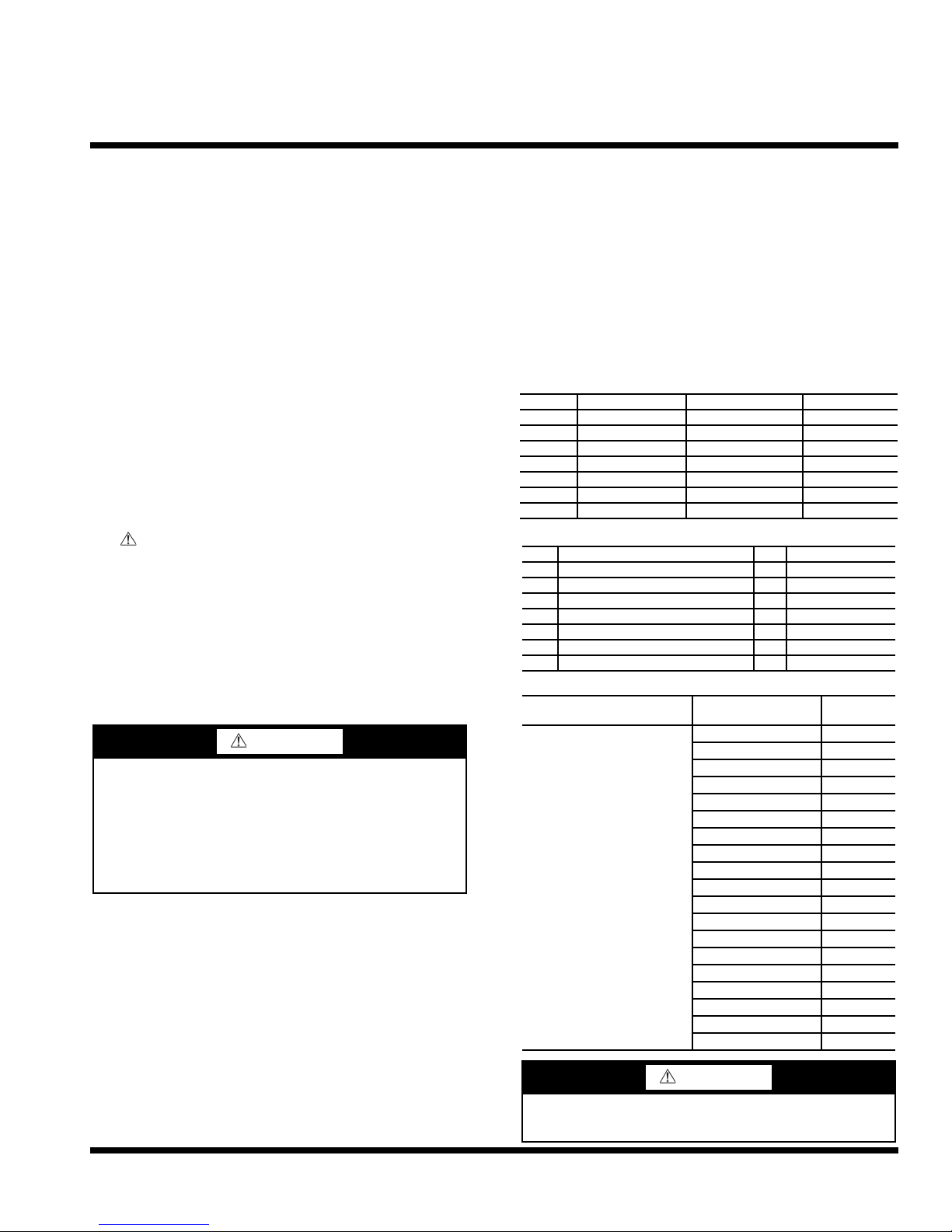
Table 1 — Control Logic
POWER SENSOR RELAYS LIGHT
OFF DRY OPEN OFF
OFF WET OPEN OFF
ON DRY CLOSED OFF
ON WET OPEN ON
ON DRY TO WET OPEN AT 10 SEC. ON AT 10 SEC.
ON WET TO DRY CLOSED AT 5 MIN. OFF AT 5 MIN.
ON DISCONNECTED OPEN BLINKS
Table 2 — Accessory Kit Contents
ITEM DESCRIPTION QTY PART NUMBER
1 INSTRUCTIONS 1 IIK-CRCNDOVR-01
2 CONTROLLER, CONDENSATE 1 HL39ZZ008
3 SCREWS, #6 x 3/8" 2 AC41AB080
4 SENSOR, 90" CONDENSATE 1 HL39ZZ009
5 BRACKET 1 48TM503400
6 SCREWS, BRACKET, #10 x 5/8" 2 AL48AM217
7 TIES, WIRE 10 Field Supplied
Table 3 — Model Usage
ACCESSORY PART
NUMBER USAGE
CRCNDOVR003A00
MODEL SIZE
48/50HC 04-14
48/50KC 04-06
48/50TC 04-16
48/50LC 04-12
50HCQ 04-12
50KCQ 04-06
50TCQ 04-14
580J/558J 04-16
581J/551J 04-14
582J/559J 04-06
547J 04-06
548J 04-14
549J 04-12
RGH/RAH 036-150
RGS/RAS 036-180
RGX/RAX 036-060
RHH 036-120
RHS 036-150
RHX 036-060
WARNING
To avoid the possibility of electrical shock, open all disconnects before installing or servicing this accessory.
Manufacturer reserves the right to discontinue, or change at any time, specifications or designs without notice and without incurring obligations.
Catalog No. IIK-CRCNDOVR-01 Printed in U.S.A. Form IIK-CRCNDOVR-01 Pg 1 8-16 Replaces: New
Page 2
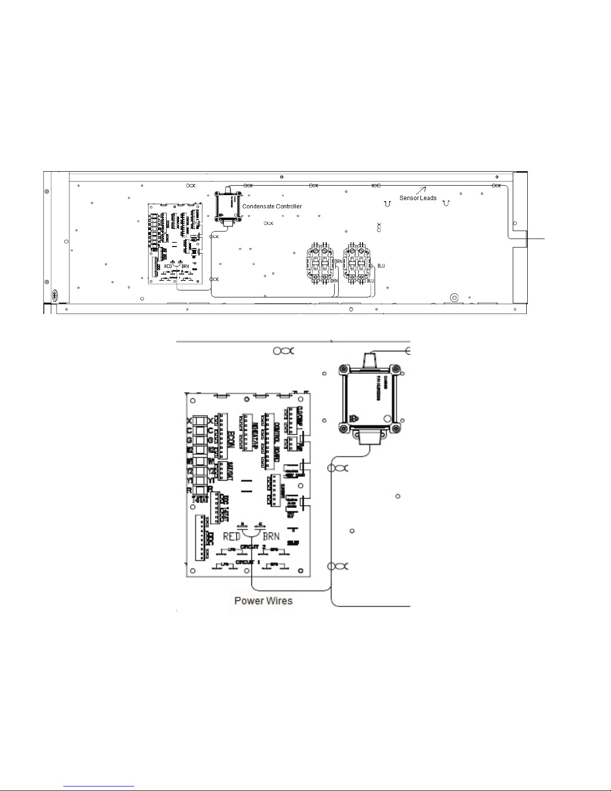
INSTALLATION
Fig. 1 — Control Box
Fig. 2 — Main Circuit Board
Step 1 — Install Condensate Overflow Switch
1. Remove panel that covers the control box.
2. Use 2 Item 3 supplied screws to fasten condensate controller to box as shown in Fig. 1.
3. Connect RED and BRN power wires from controller to
circuit board terminals as shown in Fig. 2.
Step 2 — For SINGLE Compressor Units
1. Remove wire from C1 coil and connect to BLU “Cond
1 In” wire from controller. Connect BLU “Cond 1
Out” wire from controller to open terminal on C1 coil.
See Fig. 3.
2. The (2) extra ORN wires should be tied back.
Step 3 — For DUAL Compressor Units
1. Remove wire from C1 coil and connect to BLU “Cond 1
In” wire from controller. Connect BLU “Cond 1 Out” wire
from controller to open terminal on C1 coil. See Fig. 4.
2. Remove wire from C2 coil and connect to ORN “Cond
2 In” wire from controller. Connect ORN “Cond 2
Out” wire from controller to open terminal on C2 coil.
See Fig. 4.
2
Page 3

Step 4 — Run Sensor Lead
Fig. 3 — Single Compressor
Fig. 4 — Dual Compressor
1. Remove blower compartment panel and run sensor lead
across top of box and pass through grommet on right side
for connection to sensor. See Fig. 1 and Fig. 5.
Step 5 — Install Sensor
1. If an economizer is installed on unit it must be removed
to access filter rack and condensate pan.
2. Remove air filters and filter rack. See Fig. 6.
3. Remove indoor coil bracket on left side. See Fig. 7.
4. Install sensor (Item 4) on bracket (Item 5) and tighten
thumb screw into hole in bracket. Fasten to indoor coil
bracket using (2) Item 6 screws. See Fig. 8 and 9.
5. Remove wire ties holding economizer wire harness. Place
indoor coil bracket back into slot in condensate pan as
shown in Fig. 9 and pass sensor wire into blower compartment. Leave excess wire in blower compartment for
later connection.
6. Run wire harness through U-slot while placing indoor
coil bracket back into position. See Fig. 10. Refasten with
previously removed screws and replace wire ties.
7. Reinstall filter rack and filters. See Fig. 6.
Step 6 — Connect Wire
1. Connect wire lead from controller to sensor lead and wire
tie excess wire to wire harness. See Fig. 5.
2. Reassemble unit.
3
Page 4

Fig. 5 — Sensor Wire Connection
4
Page 5

Fig. 6 — Filters and Filter Rack
Fig. 7 — Indoor Coil Bracket
INDOOR COIL BRACKET
5
Page 6

Fig. 8 — Sensor and Bracket
CORRECT INSTALLATION CORRECT INSTALLATION INCORRECT INSTALLATION
Fig. 9 — Bracket Installation
6
Page 7

REFERENCE VIEWS
Fig. 10 — Wire Harness
7
Page 8

© Carrier Corporation 2016
Manufacturer reserves the right to discontinue, or change at any time, specifications or designs without notice and without incurring obligations.
Catalog No. IIK-CRCNDOVR-01 Printed in U.S.A. Form IIK-CRCNDOVR-01 Pg 8 8-16A 8-16 Replaces: New
 Loading...