

Page 1
CB62000
Humidistat
Installation Instructions
NOTE: Read the entire instruction manual before starting the
installation.
SAFETY CONSIDERATIONS
Improper installation, adjustment, alteration, service, maintenance,
or use can cause explosion, fire, electrical shock, or other
conditions which may cause death, personal injury or property
damage. Consult a qualified installer, service agency or your
distributor or branch for information or assistance. The qualified
installer or agency must use factory--authorized kits or accessories
when modifying this product. Refer to the individual instructions
packaged with the kits or accessories when installing.
Follow all safety codes. Wear safety glasses, protective clothing,
and work gloves. Have a fire extinguisher available. Read these
instructions thoroughly and follow all warnings and cautions
included in literature and attached to the unit. Consult local
building codes and the current edition of the National Electrical
Code (NEC) NFPA 70.
In Canada, refer to the current editions of the Canadian Electrical
Code CSA C22.1.
Recognize safety information. When you see this symbol
the unit and in instructions or manuals, be alert to the potential for
personal injury. Understand the signal words DANGER,
WARNING,andCAUTION. These words are used with the
safety--alert symbol. DANGER identifies the most serious hazards,
which will result in severe personal injury or death. WARNING
signifies hazards, which could result in personal injury or death.
CAUTION is used to identify unsafe practices, which may result
in minor personal injury or product and property damage. NOTE
is used to highlight suggestions which will result in enhanced
installation, reliability, or operation.
!
WARNING
ELECTRICAL SHOCK HAZARD
Failure to follow this warning could result in personal injury
or death.
Before installing or servicing system, always turn off main
power to system. There may be more than one disconnect
switch. Lock out and tag switch with a suitable warning label.
!
CAUTION
UNIT DAMAGE HAZARD
Failure to follow this caution may result in unit damage.
Unit must not be installed where freezing temperatures could
occur. Do not install unit on the furnace or fan coil jacket. Do
not install unit where ends of cooling coil could restrict
airflow to the humidifier. Condensation damage could occur if
home has closed--off, unheated rooms.
on
INSTALLATION
INSTRUCTIONS FOR DUCT MOUNTING
(See next page for wall mounting)
Inside of Duct
Fig. 1 -- Duct--Mount Diagram
1. Turn OFF power to the humidifier.
2. The humidistat has been pre--assembled for wall mounting.
Duct mount applications will need adaptation, refer to Fig.
1.
3. Select a location on the return air duct to mount the humidistat. IMPORTANT! IT MUST BE PLACED UPSTREAM FROM THE HUMIDIFIER.
4. Using the mounting template (Fig. 3) on Pg. 3, drill the four
mounting holes using a 5/64” (2mm) drill bit. Next drill the
holes for the Humidistat Cutout Area using a 3/8” (10mm)
drill bit. Finally, drill the hole for the wire leads using a 1/4”
(7mm) drill bit.
5. Using tin snips, carefully cut out the opening for the humidistat. BE CAREFUL! METAL EDGES ARE SHARP.
Drill four corner holes to start the cut.
6. Carefully run the wire leads through the lead wire hole and
position the humidistat in the humidistat opening.
7. Fasten the humidistat to the duct with screws provided.
8. Remove the paper backing from the humidistat label and
apply to the face of the mounting base. Attach the knob to
the humidistat control shaft. Turn knob to the “off” position.
9. Join the wire leads to the thermostat cable using the wire
connectors provided. (Refer to humidifier installation instructions for system wiring options.)
Outside of Duct
A13349
Page 2

10. Turn power back ON.
11. Adjust the knob to the desired relative humidity level.
12. Allow system to level. This may take a day or two. Turning
the knob to “on” position will not reach level faster. Adjust
as needed to reach comfort level.
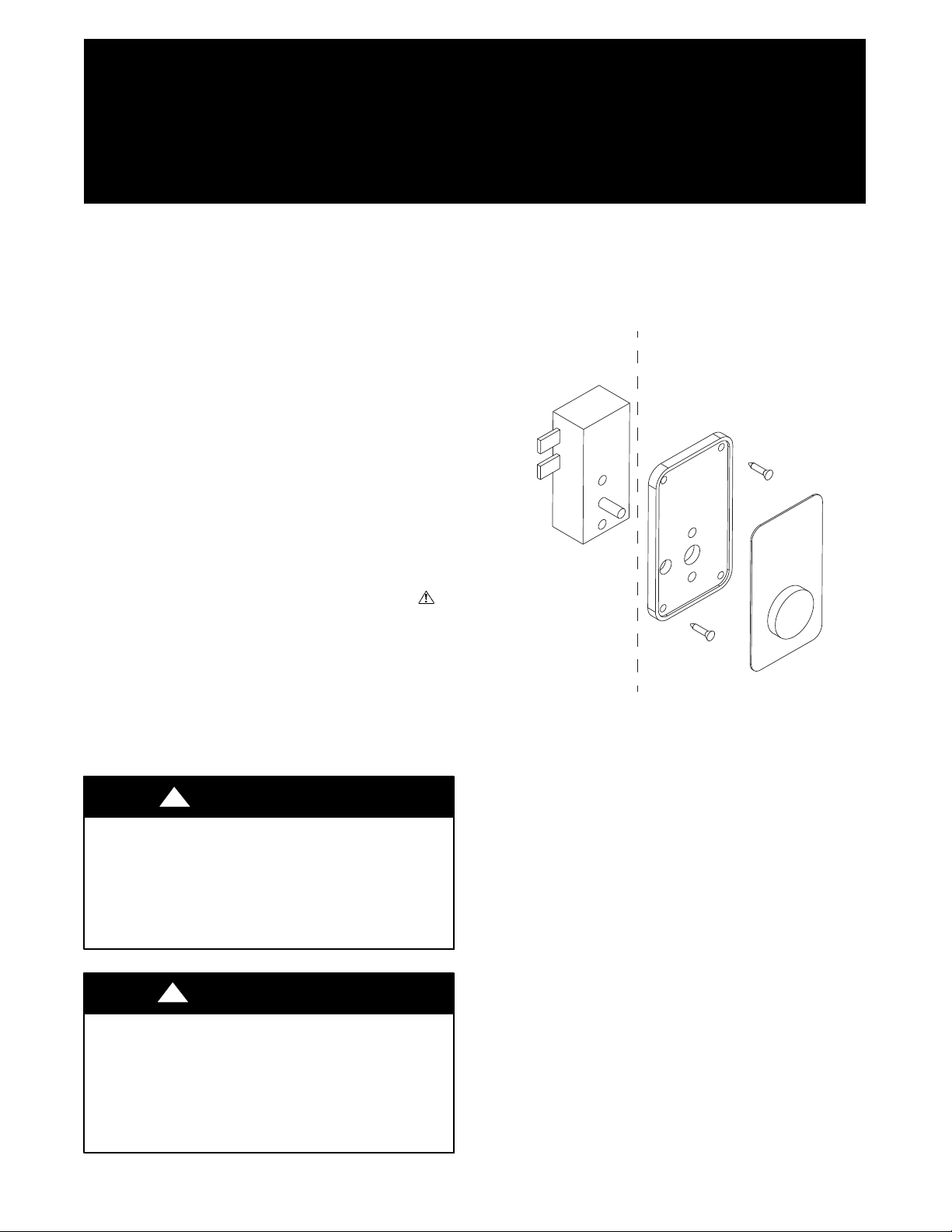
INSTRUCTIONS FOR WALL MOUNTING
A13351
Fig. 2 -- Wall--Mount Diagram
1. Turn OFF power to the humidifier.
2. Select the location for the humidistat. Choose a centrally located interior wall away from doors and windows.
3. Using the mounting template (Fig. 4) on Pg. 3, drill the four
mounting holes using a 5/64” (2mm) drill bit. Next drill the
hole for the wire leads using a 3/8” (10mm) drill bit.
4. Run the thermostat cable through the wire lead hole to the
humidifier. Ensure there is enough cable for the 24 volt
transformer also. Refer to wiring diagram. Leave about 6”
(15cm) of thermostat cable sticking out of the wall. This
will be connected to the humidistat.
5. Remove the control knob and cover. Fasten the unit to the
wall using the screws provided. Use appropriate anchors
(sold separately) when fastening to drywall.
6. Join the wire leads to the thermostat cable using the wire
connectors provided.
7. Replace the cover on the unit. Remove the paper backing
from the humidistat label and apply to the face of the cover.
Attach the knob to the control shaft. Turn knob to the “off”
position.
8. Connect thermostat cable to the humidifier and transformer.
(Refer to humidifier installation instructions for system
wiring options.)
9. Turn power back on.
10. Adjust the knob to the desired relative humidity level.
11. Allow system to level. This may take a day or two. Turning
the knob to “on” position will not reach level faster. Adjust
as needed to reach comfort level.
2
Page 3
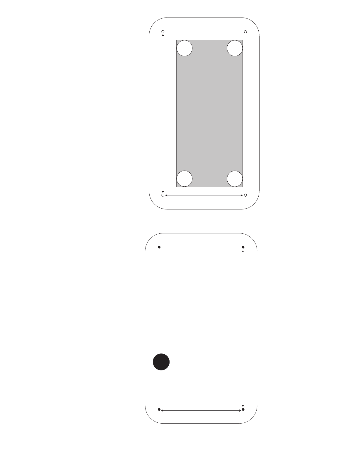
HUMIDISTAT CUT OUT AREA
MOUNTING
HOLE (4)
CORNER HOLES
TO START CUT
←
1-1/2” (38mm)
→
MOUNTING
HOLE (4)
3-5/8” (92mm)
1-7/8” (47.6mm)
Fig. 3 -- Duct--Mount Template
↑
HUMIDISTAT CUT OUT AREA
HUMIDISTAT CUT OUT AREA
3-3/8” (86mm)
A13350
LEAD WIRE
HOLE
→
3-5/8” (92mm)
1-7/8” (47.6mm)
A13352
Fig. 4 -- Wall--Mount Template
3
Page 4

Copyright 2013 CAC/BDP. S 7310 W. Mo rris St. S Indianapolis, IN 46231
Manufacturer reserves the right to change, at any time, specifications and designs without notice and without obligations.
4
Edition Date: 10/13
Catalog No: IIK--- CB62000 --- 01
Replaces: NEW
 Loading...