

Page 1

73X,Y
HEATING & COOLING
Start-Up and Service Instructions
CONTENTS
Page
START-UP.................................................................1
SERVICE ...................................................................1,2
General Notes
Compressor Replacement
SAFETY REMINDERS
PREVENTIVE MAINTENANCE
General .......................................................................2
System Cleaning/Flushing.......................................2
DISASSEMBLY INFORMATION .......................... 5 12
Filter Removal ...........................................................5
Front Grille Removal
Control Box Removal.............................................. 5
Thermostat Bulb Heater Removal
Mode Switch Control Removal............................... 7
Timer Assembly Removal
(Models 73YCA213P and 73YCA243P
Only)....................................................................... 7
Capacitor Removal ................................................. 7
Indicator Light Removal
(Models 73YCA213P and 73YCA243P
Only)....................................................................... 8
Indoor Thermostat Removal
Fan Cycle Switch (Energy Saver Switch)
Removal ................................................................. 8
Air Sweep Switch Removal
(Models 73YCA213P and 73YCA243P
Only)....................................................................... 8
Chassis Removal .................................................... 8
Air Sweep Motor Removal
(Models 73YCA213P and 73YCA243P
Only)....................................................................... 8
Evaporator and Condenser Coils Removal ... 8
Air Handling System Removal
Exhaust Door Removal
Vent Door Removal
(Models 73YCA213P and 73YCA243P
Only)....................................................................... 9
Indoor Blower Wheel Removal
Outdoor Propeller Fan Removal............................ 10
Fan Motor Removal
Compressor Removal ............................................ 11
Strainer Removal and Replacement
Electric Heater Assembly Removal
SERVICE POINTS ................................................... 13
TROUBLESHOOTING ..............................................14
...........................................................
.......................................
...............................................
...............................
...............................................
........................
.................................
..............................
..........................................
..............................
...............................................
.....................
.....................
1
2
2
2-4
5
7
8
9
9
10
11
11
11
1993 Room Air Conditioners
START-UP
Refer to operating instructions in Owner’s Guide pro
vided with room air conditioner
SERVICE
General Notes — These Start-Up and Service Instruc
tions are provided to assist the trained and qualified service
technician in repairing or replacing components of Carrier
room air conditioner model offerings for 1993. These
instructions contain disassembly photos for the Models
73XC,XH, and YC. Unit physical data is found in
Tables 1-9.
IMPORTANT; Repairing and servicing air condition
ers can be hazardous for untrained individuals. The
instructions printed in this publication are for prop
erly trained and qualified Carrier service technicians
only.
A WARNING
Before working on any air conditioner, be sure to first
disconnect all electric power to the unit to avoid the
possibility of electrical shock and personal injury.
Discharge capacitors before disconnecting, by shorting
across terminals.
Shield coils with cardboard to protect hands against in
jury from sharp metal edges when removing compressor and
other components.
When disassembling wiring, use numbered stickers to iden
tify wire leads and terminals. This aids in quick, accurate
reassembly.
Check clearances around scroll and housing before in
stalling fans. Before securing fan(s) fasteners, rotate fan by
hand to ensure ample clearance.
Refer to Carrier Standard Service Techniques, Chapters
1 and 2, for information on checking motors; removing
refrigerant; adding oil; and evacuating, dehydrating, and charg
ing system. Pay particular attention to all safety warnings
for these procedures.
NOTE: In Carrier Standard Service Techniques, refrigerant
removal must always include reclaiming the refrigerant, not
allowing it to escape to the atmosphere.
Manufacturer reserves the right to discontinue, or change at any time, specifications or designs without notice and without incurring obiigations.
BookM 14 PC 131 Catalog No 537-320 Printed in U S.A Form 73X,Y-1SS Pg 1 3-94 Replaces: New
Tab 8a 10a
Page 2

1
Compressor Replacement — Stand dear of com
pressor terminals when working on compressors. With sys
tem under pressure, terminals may blow. Observe the same
.safety procedures for rotary compressors as for reciprocat
ing compressors.
When changing compressors:
1. Follow all safety codes. Reminder, use protective
goggles, work gloves, and water-soaked quenching
cloth
2. Shut off all electrical power to unit by removing power
cord from outlet, then disconnect all wiring from the
compressor.
3. Apply field-supplied tap-a-lines to the true (closest to
compressor) suction and discharge connections of the
compressor.
Recover the refrigerant charge from the unit. After re
4.
covering, cut the discharge and suction line process tubes
below the tube crimps. If you choose a good tubing
location for cutting the refrigerant lines initially, the
location is easily accessible when making the final joints.
You can braze the oil piping stub into the new com
pressor fittings more easily before the compressor is
put back into the unit.
A CAUTION
Oil vapor in piping stubs can ignite from torch flame
and cause serious injury. Exercise extreme care when
brazing, and keep brazing cloth and fire extin
guisher handy for emergency use.
5. Connect a nitrogen supply to the unit at one of the tapa-line connectors (5 psig maximum flow), leaving the
other connector open to the atmosphere. Braze angle
valves with stubs to each process tube.
6. Remove compressor from unit. Refer to Compressor
Removal, page 11.
7. Remove tap-a-llnes from suction and discharge lines
Carefully braze the holes closed from where the tap-alines were removed.
8. Clean system: add or replace liquid line filter drier.
For proper cleaning and flushing, use the Carrier
Totalclaim® reclaim system or a comparable refrig
erant recycling system.
9. Install new compressor and braze into place with fieldsupplied copper slip couplings.
10. Connect wiring: replace wire terminals if necessary.
11. Proceed with evacuation and charging. Pinch off lines
where angle valves were added. Cut off angle valves
above pinch-off, and braze tubes.
12. Start up unit.
SAFETY REMINDERS
1. Carry a fire extinguisher in your truck. Keep it within
reach when using a torch. Check fire extinguisher peri
odically to be sure it is fully loaded and functional.
2. Know how to handle oxyacetylene equipment safely. Lock
the equipment in an upright position in the truck and at
the job site.
3. Use dry nitrogen or carbon dioxide to pressurize the sys
tem for leak checking. Always use a good regulator. Be
careful not to exceed 150 psig test pressure in the her
metic compressor.
4. Wear safety goggles and gloves when recovering refrig
erant from a system,
5. Attend shop safety meetings.
PREVENTIVE MAINTENANCE
General
CLEANING — Clean cooling coil and condenser coil. Hold
flashlight behind coil to see If all spaces are clear. Use a
hooked wire to remove dirt. Dust accumulation obstructs or
reduces airflow and results in loss of capacity. Coils may
be vacuumed when dry. Outdoors, unit can be brushed with
a stiff brush and fins blown out with compressed air.
Thoroughly clean basepan, motors, fan wheels, other com
ponents, and all drain passages. Vacuum insulation. Clean
all Inside painted surfaces with mild detergent to remove
grease.
Clean cabinet and grille. Mild detergents reduce electro
static charges on plastic sections of the grille and are good
cleaners.
containing solvents to clean plastic sections.
PAINTING — Paint any parts that show evidence of rust
with a good rust-resistant paint.
WIRING — Check all wiring for deterioration and all elec
trical contacts for tightness and lack of corrosion.
MOUNTING — Make sure unit is secure in window, and
level from left to right and from front to rear according to
installation instructions provided.
tered in orifice, and tight on shaft.
LEAKS — Check any connections that show evidence of
oil or leaks. When unit is properly installed, centered, and
leveled (see Owners’ Guide), check gaskets and wing pan
els for possible air leakage.
CONTROLS — Check unit to ensure all controls are func
tioning correctly and unit operation is normal.
no piping is vibrating against any side of unit.
System Cleaning/Flushing — For proper cleaning
and flushing, use the Carrier Totalclaim reclaim system, or
a comparable refrigerant recycling system.
Do not use carbon tetrachloride, solvents, or waxes
Check fans to ensure they are correctly positioned, cen
Vibrations can cause unwanted noise. Check to be sure
SP
Page 3

Table 1 — Physical and Electrical Data (Single Phase, 60 Hz) — 1993
MODEL
73
XHA101D
XCA121D
XCA123D
XHA123D
XCA153D
XHA153D
XHA173D
XCA183D
YCA213D
YCA213P
YCA243D
YCA243P
MODEL
73
XHA101D
CASING
(See
Table 6)
305 9,100
305 12,000
305
305 12,000/11,600 9,200/ 7,600
305 15,000/14,700
305
305
305 17,800/17,500
405
405 21,000/20,800
405
405 23,500/23,000
CAPACITOR
(See Table 5)
CAPACITY (Btuh)*
Cooling
Heating
5,200
— 37 5
12,000/11,600
-
15,000/14,700
17,100/16,700
14,600/11,800 38
16,300/12,900 38
21,000/20,800
—
—
23,500/23,000
-
-
FAN MOTOR
Carrier
Part Number
RC-1 25901023 1 88
FLA
XCA121D RC-1 25901023 1.88
XCA123D
XHA123D RC-1
XCA153D
XHA153D
XHA173D
XCA183D
YCA213D RC-2
YCA213P
YCA243D
YCA243P
RC-1 25901026 0.98
25901026 0 98
RC-1 25901031 0 99
RC-1
RC-2 25901018
RC-2 25901018
RC-2
RC-3 25901024 1.54 T-1
RC-3
25901031
25901024 1.54 D-2 z-1
25901024 1.54
25901024 1 54 T-1 z-1
0 99 D-1
1.24 D-3 z-1 V4 CD-3
1.24 D-3 z-1
LEGEND
AHAM — Association of Home Appliance Manufacturers
ANSI — American National Standards Institute
DOE — Department of Energy
EER — Energy Efficiency Ratio
FLA — Full Load Amps
PF — Power Factor
R-22
WET
CHG
BULB
(oz.
± .05)
29 5
AtF
103
Volts
10.0 115
125 230/208
37 5
12.5 230/208
37.5
230/208
24 1
38
230/208 253-187 6 5/70 20.9/19 0 1470/1440 4790/3950 10 2/10.2 98/99
97
97 230/208
24.6 230/208
38
21.8 230/208
47
21.8 230/208
47
24.1 230/208
51
51 24.1 230/208
COMPRESSOR
(See Table 2)
H-1 Z-1
H-2
H-3 z-1 - CD-6 CI-1 2
H-3 z-1 V2
D-1 z-1
D-2
Voltage
Range
127-104
115
127-104
253-187
253-187 5 2/ 5.5
253-187
253-187
253-187 8.2/ 8 9
253-187
253-187
253-187
253-187
THERMISTOR
NAMEPLATE
Amps
Cool Heat
9.0
16 1 1020
105
5 2/55
13.4/12 3
6 5/ 7.0
-
-
-
Watts
Cool Heat
1200
1180/1140
1840
-
-
EER
(DOE)PF(%)
9.0 98
10.0 99
10 2/10.2 98/99
1180/1140 3080/2540 10.2/10 2 98/99
1470/1440
-
10 2/10.2 97/99
7 9/ 8.5 22 7/20.8 1800/1750 5220/4320 9 5/ 9.5 99/98
- 1870/1840 - 9.5/ 9 5 99/99
10 4/11.3 - 2290/2260 - 9 2/ 9.2
10.4/11.3
- 2290/2260 -
12.0/12.7 - 2670/2610 - 8 8/ 8.8
12 0/12.7
HEATER
(See Table 4)
Z-1 - CD-6 CI-1 2
z-1
z-1
z-1
ASSEMBLY
(See Table 3)
-
VI
V3
-
-
-
-
-
-
2670/2610
-
CAPILLARY
(See Tables 7 and 8)
Data Insertion
CD-4 CI-1 1
CD-6 CI-1
CD-I
CD-I
CD-3
CD-2 CI-1 3
CD-2
CD-5
CD-5
CI-1
CI-1 3
CI-1
CI-1
CI-1
CI-1 3
CI-1
9 2/92
8 8/88
96/96
96/96
97/99
97/99
Number
of Tubes
2
3
3
3
3
3
•Based on AHAM Standard RAC-1 and ANSI Z234 1
At — Entering wet-bulb temperature minus leaving wet-bulb temperature
based on 67 F room wet-bulb temperature and 95 F dry-bulb outside-air
temperature If conditions vary, wet-bulb At will vary
KEY NUMBER
(See Table 1)
D-1
D-2 P033-2221 23.0 230/208 50 0 9.1
D-3 P033-1821
H-1 P031-1004
H-2 P031-1103
H-3
T-1 P035-2522
LEGEND
LRA — Locked Rotor Amps
FLA — Full Load Amps
Table 2 — Compressors
REPLACEMENT
PART NUMBER
P033-1521 13.0
P031-1122
OIL RECHARGE
(oz.)
VOLTS
(1 Ph, 60 Hz)
LRA FLA
230/208 33 2
13.0
9.1
9 1
9.1
230/208 38 0 74
115 48 3
115 54 0 160
230/208 26.3
183 230/208 63.0 107
59
8.6
4.8
Page 4

Table 3 — Heater Assemblies
Table 6 — Casing Dimensions (in)
HEATER
ASSEMBLY
(See Table 1)
VI
V2
V3
V4
LS — Limit Switch
KEY NUMBER
(See Table 1)
Z-1
KEY NUMBER
(See Table 1)
RC-1
RC-2
RC-3
PRIMARY
KILOWATTS
1.6 140 200
2.8
4.5 140 200
5.0
LS
(F)
140 200
140 210
SECONDARY
Table 4 — Thermistor
CARRIER VENDOR
NUMBER NUMBER (Ohms)
42320001
CM305C20C
RESISTANCE
Table 5 — Capacitor
CARRIER
NUMBER
05706028
05706030 30/5
05706031 45/5
MFD
25/5
LS
(F)
25
VOLTS
370
370
370
KEY NUMBER
(See Table 1)
305 16% 25% 6 23%4
405 17% 6 26 27% 6
HEIGHT WIDTH DEPTH
Table 7 — Capillary Data
(See Table 1)
CD-I
CD-2
CD-3
CD-4 1 Tube - 28 7
CD-5
CD-6
Length (± .002) ID (± .002)
1 Tube — 47.0 1 Tube - .054
2 Tubes — 64 0 2 Tubes — 054
2 Tubes — 29.3
1 Tube - 56 3
1 Tube — 47.0
2 Tubes — 29.3 2 Tubes — 054
1 Tube - 39.5
2 Tubes — 29.3
2 Tubes — 40 5
2 Tubes — .054
2 Tubes — .054
Table 8 — Capillary Insertion
DEPTH (In.)
(See Table 1)
CI-1 1 1
Condenser Coll
Connection Tube
Evaporator Coil
Connection Tube
2 Tubes — 054
1 Tube - .064
1 Tube - .054
1 Tube — .064
1 Tube — .054
DEPTH (in.)
Table 9 — Receptacles, Fuse Types, Wire Sizes
UNIT NAMEPLATE VOLTAGE 115
MAXIMUM NAMEPLATE AMPS
OUTLET RATED VOLTS/AMPS
RECEPTACLE CONFIGURATION
12
125/15
©
MFR PART NO.
Hubbell
P & S
GE
Arrow-Hart
TIME-DELAY FUSE OR CIRCUIT
BREAKER SIZE (AMPS)
FUSE TYPE
RECOMMENDED AWG
WIRE SIZEt
AWG — American Wire Gage
‘May be used for 15-amp applications if fused for 15-amp.
tBased on copper wire at 60 C temperature rating.
5261
6201
GE5261-1
5261
15
14 12
PI
ug
16
125/20
©
5361
5361
GE4102-1
5361
20*
12
250/15
©
5661
5661
GE4069-1
5661
15
14
230/208
16
250/20
©
5461
5871
GE4182-1
5861
20*
Cartridge
12
24
250/30
©
9330
5930
GE4139-3
5700
30
10
Page 5

DISASSEMBLY INFORMATION
A WARNING
Before working on any air conditioner, be sure to first
disconnect all electric power to unit to avoid the pos
sibility of electrical shock and personal injury.
Models 73X,Y Room Air Conditioners have the follow
ing characteristics;
_________
UNIT
73XC Cooling Only
73XH
73YC Cooling Only
FUNCTION
Heat/Cool
CASING
305
305
405
All units have a slide-out chassis. Units can be serviced
without removing casing.
Filter Removal
Place index fingers inside the openings on either side of
1.
the filter frame. See Fig. 1.
Apply pressure inward toward the center, while pulling
filter down and out.
Vacuum filter, or wash in lukewarm water. Shake off
3.
excess water and dry thoroughly.
Replace filter by sliding filter upward behind front grille
4.
until filter snaps in place.
SCREW (HIDDEN) SCREW (SECURITY)
Fig. 2 - Removing 2 Screws from Front Grille
Fig. 3 - Removing Front Grille
Control Box Removal
1. Slide chassis part way out of casing to access control
box.
A CAUTION
Use care when sliding chassis out of unit so that it
does not fall from casing. Personal injury and/or
damage to unit and surroundings can result.
Fig. 1 — Removing Filter
Front Grille Removal
1. Remove 2 screws located on either side of front grille.
See Fig. 2.
NOTE; Facing the front of unit, grille screw on the righthand side serves as a unit security screw.
2. Pull grille out and upward, removing it from chassis.
See Fig. 3.
3. To replace grille, place grille top on unit top edge and
firmly press grille back into position.
4. Replace screws.
NOTE; Sliding chassis partly out of casing ensures that
the wiring does not become pinched when the control
box is replaced. See Fig. 4.
2.
Remove front grille. Refer to Front Grille Removal on
this page.
Carefully remove thermostat and mode switch control
3.
knobs by pulling them straight out and off. See Fig. 5.
Grasp escutcheon located in lower right-hand corner of
unit and apply pressure on both sides towards the cen
ter. See Fig. 6. Carefully disengage ¿scutcheon plastic
tabs from sheet metal slots and remdve.
5.
Remove 2 screws securing control box to chassis. See
Fig. 7.
6.
Disengage plastic clip, then ybmove sensing bulb with
attached bulb heater from coil face. See Fig. 7.
Page 6
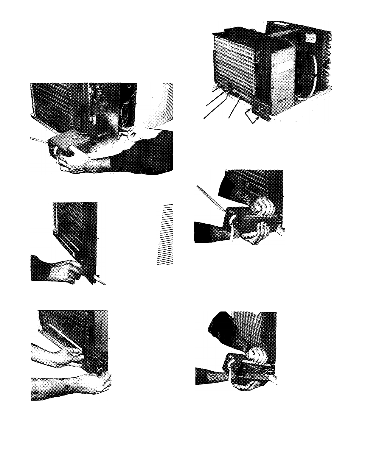
7. Carefully pull control box straight out from unit.
8. On right side and bottom of control box, manually dis
engage removable sheet metal panel to access control
box components. See Fig. 8. See Fig. 9 for control box
components.
9. Reverse above procedure for reassembly, taking care
not to pinch any wiring inside the control box. This is
accomplished by guiding the wiring from the rear of the
control as shown in Fig. 4.
Fig. 4 — Removing Control Box
SENSING
BULB
METAL
CLIP
BULB
HEATER
Fig. 7
BRAIDED
SLEEVE
SCREWS (2)
Removing Screws Securing Control Box
to Chassis
Fig. 5 — Removing Knobs
Fig. 6 — Removing Escutcheon
GRASP PANEL
LIFT PANEL
TO REMOVE
Fig. 8 - Removing Sheet Metal Panel
Page 7
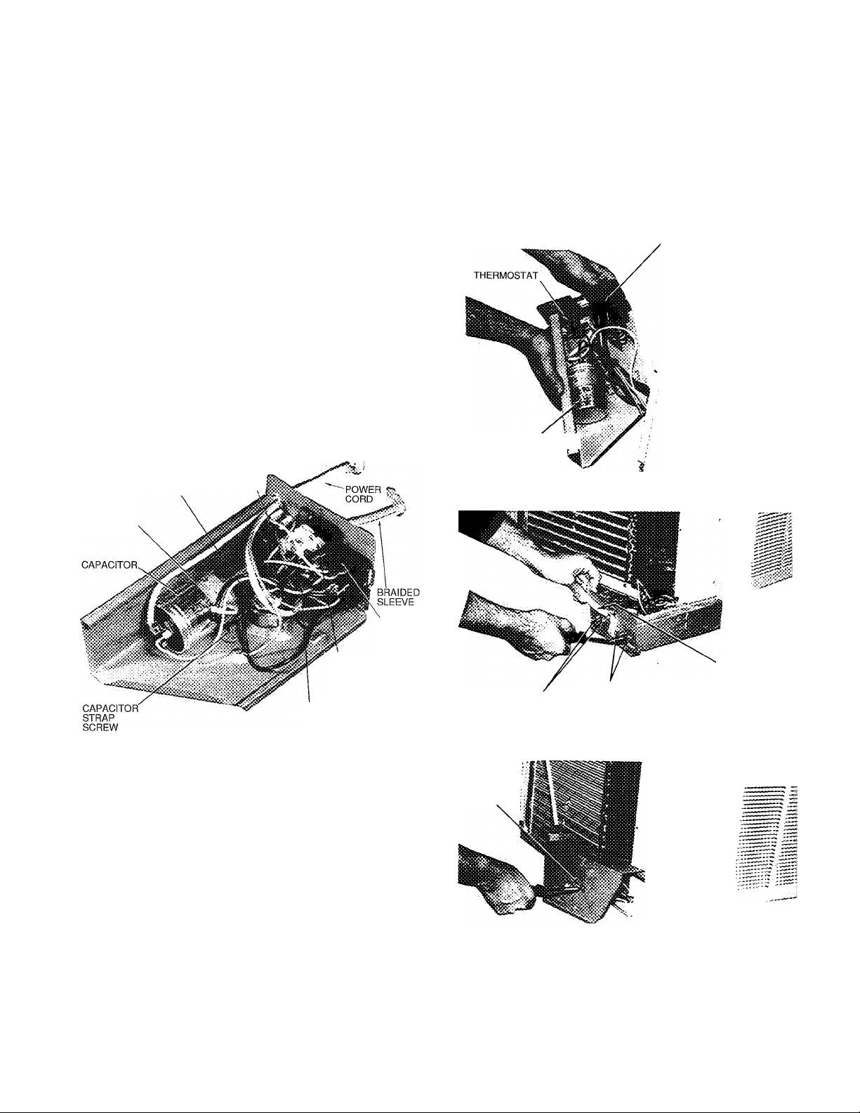
Thermostat Bulb Heater Removal — Use care
not to damage sensing bulb or capillary of thermostat when
handling bulb heater. See Fig. 7.
1. Slide out control box. Refer to Control Box Removal
instructions, page 5.
2. Carefully disconnect bulb heater wires from terminals
Inside control box. Label wires to aid in reassembly.
3. Remove plastic clip used to hold thermostat sensing bulb,
bulb heater, and braided sleeve to coil. (See Fig. 7.)
4. Carefully remove metal clip which connects bulb heater
to sensing bulb.
5. Carefully remove bulb heater wires from braided sleeve
(Fig. 7).
6. Reverse above procedure for reassembly.
Mode Switch Control Removal (See Fig. 9 and
10)
1. Slide out control box. Refer to Control Box Removal
instructions, page 5.
2. Remove 2 screws holding mode switch control to con
trol box. See Fig. 11.
3. Carefully disconnect wires from mode switch control.
Label wires to aid in reassembly.
4. Reverse above procedure for reassembly.
Capacitor Removal
1. Discharge capacitor before removing.
2. Slide out control box. Refer to Control Box Removal
instructions, page 5.
3. Remove screw fastening capacitor strap to control box
and remove strap. (See Fig. 9, 10 and 12.)
4. Carefully disconnect wires from capacitor terminals.
Label wires to aid in reassembly.
5. Reverse above procedure for reassembly.
MODE SELECT SWITCH
CAPACITOR Í \
AIR SWEEP MOTOR
(MODELS
73YCA213P, 243P ONLY)
CAPACITOR
STRAP
THERMOSTAT
\
MODE
SELECT
SWITCH
TIMER ASSEMBLY
(MODELS
73YCA213P, 243P
ONLY)
INDICATOR LIGHT WIRES
(MODELS 73YCA213P AND
243P ONLY)
Fig. 9 — Control Box Components
Timer Assembly Removal (Models 73YCA213P
and 73YCA243P Only)
1. Slide out control box. Refer to Control Box Removal
instructions, page 5.
2. Carefully disconnect wires from timer assembly
(Fig. 9). Label wires to aid in reassembly
3. Remove 2 screws securing timer to control box and re
move timer from rear of control box.
4. Reverse procedure for reassembly.
Fig. 10 - Components Layout
BRAIDED SLEEVE
(PROTECTS
THERMOSTAT
SCREWS
SCREWS TO
REMOVE MODE
SELECT SWITCH
SENSOR
BULB AND BULB
HEATER)
Fig. 11 — Removing Thermostat and Bulb Heater
CAPACITOR
STRAP
SCREW
Fig. 12 — Removing Capacitor Strap Screw
Page 8
P
Indicator Light Removal (Models 73YCA213P
and 73YCA243P Only)
Slide out control box. Refer to Control Box Removal
1
instructions, page 5.
Carefully disconnect indicator light wires (Fig. 9 and
2.
13) from termination connections. Label wires to aid in
reassembly.
3. Remove light by pulling straight out through front of
control box.
4. Reverse above procedure for reassembly.
Indoor Thermostat Removal — indoor thermostat
is a vapor-filled device with an attached bulb heater. Be
careful not to bend or kink the thermostat-sensing bulb or
capillary. See thermostat location in control box in Fig. 10.
1. Slide out control box. Refer to Control Box Removal
instructions, page 5.
2. Remove 2 screws securing thermostat to control. See
Fig. 11.
3. Carefully disconnect wires from thermostat terminals.
Label wires to aid in reassembly.
4. Remove plastic clip used to hold bulb heater, sensing
bulb, and braided sleeve to coil. (See Fig. 7.)
5. Remove metal clip which connects bulb heater to sens
ing bulb. (See Fig. 7.)
6. Carefully slide sensing bulb from protective sleeve. It is
not necessary to remove the bulb heater from the braided
sleeve.
7. Remove thermostat from control box.
8. Reverse above procedure for reassembly.
Fan Cycle Switch (Energy Saver Switch)
Removal
1. Slide out control box. Refer to Control Box Removal
instructions, page 5.
2. Disconnect wires from switch. Label wires to aid in
reassembly.
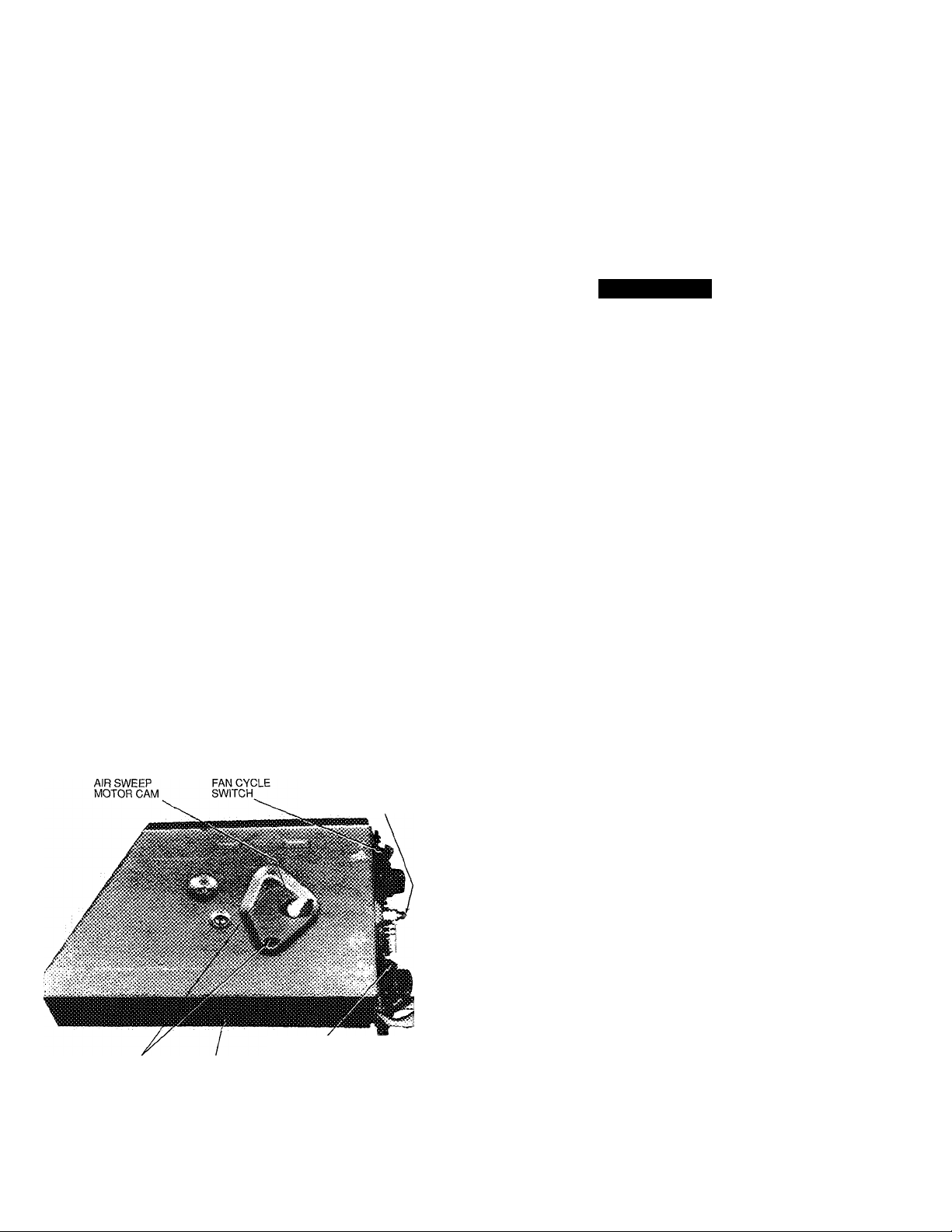
3. Remove 2 screws securing fan cycle switch (Fig. 13)
and remove switch.
4. Reverse above procedure for reassembly.
INDICATOR LIGHT
(MODELS 73YCA213P
AND 243P ONLY)
AIR SWEEP
SWITCH (MODELS
SCREWS FOR
AIR SWEEP MOTOR
73YCA213P AND
243P ONLY)
Fig. 13 — Removing Air Sweep Motor
Air Sweep Switch Removal (Models 73YCA213P
and 73YCA243P Only)
1. Slide out control box. Refer to Control Box Removal
instructions, page 5.
2. Disconnect wires from switch. Label wires to aid in
reassembly.
3. Remove 2 screws securing air sweep switch (Fig. 13)
and remove switch.
4. Reverse above procedure for reassembly.
Chassis Removal
A CAUTION
Coil fins are sharp. Use care when removing chassis
from casing to avoid personal injury. Do not use plas
tic parts for lifting or pulling. They are not structural
members of the chassis. Lift using basepan only. Chas
sis is heavy. Obtain assistance for lifting.
Chassis can be serviced without removing unit casing from
window or wall location.
1. Remove front grille. See Front Grille Removal instruc
tions, page 5.
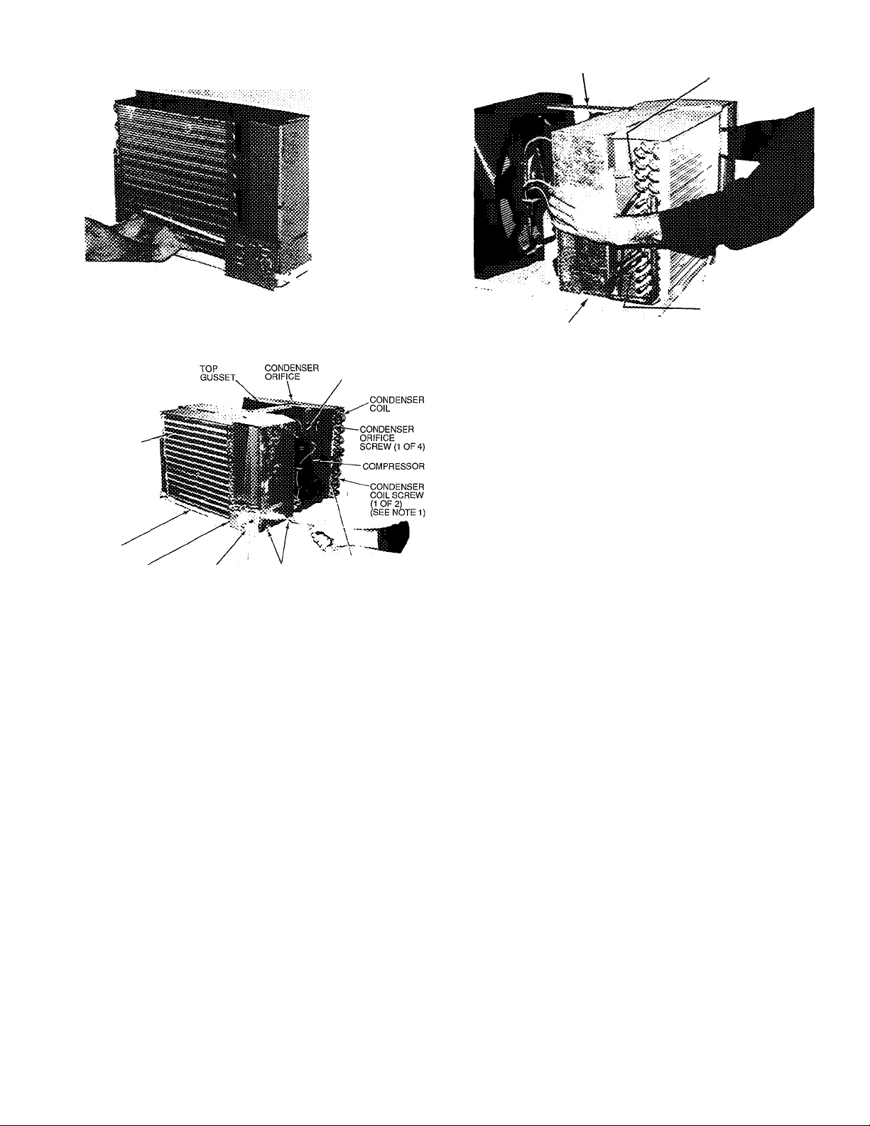
2. Slide chassis out of casing. See Fig. 14.
3. Reverse above procedure to reinstall chassis in casing.
Be sure to replace and tighten left-hand screw and righthand security screw on the front grille.
Air Sweep Motor Removal (Models 73YCA213P
and 73YCA243P Only)
1. Remove control box. See Control Box Removal instruc
tions, page 5.
2. Carefully disconnect air sweep motor (Fig. 9) wire
terminations.
3. Carefully pull plastic air sweep motor cam from shaft.
See Fig. 13.
4. Remove 2 screws securing air sweep motor to control
box and remove motor.
5. Reverse above procedure for reassembly.
Evaporator and Condenser Coils Removal (See
Fig. 15)
NOTE; Coils and interconnecting tubing are copper.
1. Reclaim all refrigerant from system using a Carrier
Totalclaim® or Carrier Totalsave recovery system, or a
comparable refrigerant recovery system. Refer to Serv
ice section, page 1.
2. Remove chassis from casing. See Chassis Removal in
structions, above.
3. Remove air handling system. See Air Handling System
Removal instructions, page 9.
4. Cut interconnecting tubing and remove evaporator coil
from basepan by removing 2 evaporator screws. See
Fig. 15.
5. Cut interconnecting tubing and remove condenser coil
from basepan by removing 2 condenser coil screws. See
Fig. 15.
6. Reverse above procedure for reassembly.
Page 9
TOP GUSSET
SCREW SECURING
EVAP SCROLL TO
EVAP TUBE SHEET
Fig. 14 — Removing Chassis
COMPRESSOR
TERMINAL
COVER
EVAPORATOR
COIL
EVAPORATOR
SCREW
{1 OF 2)
BASEPAN
EVAPORATOR-" POWER PARTITION ORIFICE SCREW
SCREW (1 OF 2) CORD SCREWS (2) (1 OF 4)
NOTES:
1 Second condenser coil screw is iocated on the back of unit.
2. Third and fourth condenser orifice screws are iocated in same
area on opposite end of condenser orifice
CONDENSER
Fig. 15 — Unit Chassis
Air Handling System Removal
1. Remove chassis from casing. See Chassis Removai in
structions, page 8.
2. Remove 2 screws securing partition to basepan as shown
in Fig. 15, and one screw on left side (Fig. 16), and one
screw on rear side of partition (Fig. 17), in area of
motor.
3. Remove 2 screws securing evaporator scroll to evapo
rator tube sheet. See Fig. 16.
4. Remove 4 screws (2 on right side and 2 on left side)
securing condenser orifice to condenser coil tube sheet.
See Fig. 15 for location of right-side screws; left-side
(2) screws are in similar location on left side.
5. Remove compressor terminal cover. Disconnect wires
from compressor and external overload protector termi
nals. Label wires to aid in reassembly. See Fig. 15.
NOTE: Not all models have compressors with external
overload protectors; certain models use compressors with
internal overload protectors
6. Remove fan motor clip. See Fig. 17.
LEFT SIDE
PARTITION SCREW'
SCREW SECURING
EVAP SCROLL TO
EVAP TUBE SHEET
Fig. 16 — Preparing to Lift Air Handling System
7. Carefully disengage one of the vertical air deflectors, al
lowing access to assist in removing air handling system
assembly. See Fig. 18.
8. Carefully lift assembly from chassis. See Fig. 19.
9. Reverse above procedure for reassembly, ensuring air
handling system is positioned correctly. Tighten all screws.
Exhaust Door Removal (See Fig. 20)
1. Remove chassis from casing. See Chassis Removal in
structions on page 8.
2. Remove air handling system. See Air Handling System
Removal Instructions, on this page.
3. Remove control box from chassis. See Control Box Re
moval instructions, page 5.
4. Remove 3 screws securing partition to indoor plastic scroll.
(See Fig. 21.)
5. Carefully separate sheet metal partition slots from scroll
tabs on both sides by spreading sheet metal sides apart.
Remove scroll from sheet metal partition. (See Fig. 22.)
Exhaust door and cable assembly from door to rotary
knob (Fig. 20) are now exposed for required repairs or
adjustments.
6. Reverse above procedure for reassembly.
Vent Door Removal (Models 73YCA213P and 73YCA243P Only) (See Fig. 20)
1. Remove chassis from casing. See Chassis Removal in
structions, page 8.
2. Remove air handling system. See Air Handling System
Removal instructions, on this page.
3. Remove control box from chassis. See Control Box Re
moval instructions, page 5.
4. Remove 3 screws securing center partition to indoor plas
tic scroll. See Fig. 21.
5. Carefully separate sheet metal partition slots from scroll
tabs on both sides by spreading sheet metal sides apart.
Remove scroll from sheet metal partition. See Fig. 22.
Vent door and cable assembly from door to rotary knob
(Fig. 20) are now exposed for repairs or adjustments.
6. Reverse above procedure for reassembly.
Page 10
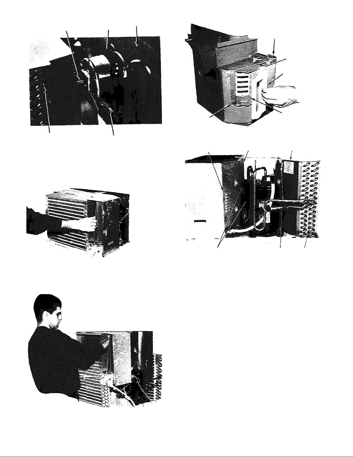
FAN MOTOR
CLIP (SPRING)
FAN
MOTOR
PARTITION
ROTARY KNOB
CABLE
VENT DOOR
(73YCA213P
AND 243P ONLY)
AIR HANDLING SYSTEM
REMOVAL SCREW
LEFT SIDE SCREW TOP
REAR SIDE
PARTITION SCREW
Fig. 17 — Removing Fan Motor Clip
Fig. 18 — Disengaging Vertical Air Deflector
EXHAUST
DOOR
EXHAUST DOOR
SPRING CLIP
Fig. 20 — Indoor Plastic Scroll Assembly
INDOOR PLASTIC
SCROLL (HIDDEN)
SCREWS
(2 OUT OF 3)
NOTE: Third screw is located on left side of partition as viewed from
front of unit.
SHEET METAL
PARTITION
TYPICAL STRAINER
LOCATION
CONDENSR
ORIFICE
CONDENSER
COIL
Fig. 21 — Screws Securing Partition to indoor
Plastic Scroll Assembly
Fig. 19 — Removing Air Handling System
Indoor Blower Wheel Removal (See Fig. 22)
1. Remove chassis from casing. See Chassis Removal in
structions, page 8.
2. Remove air handling system. See Air Handling System
Removal instructions, page 9.
3. Mark shaft at a point where wheel hub and motor shaft
meet to aid in reassembly.
4. Remove spring metal clip from blower wheel hub. See
Fig. 22.
5. Slide off blower wheel from motor shaft.
6. Reverse above procedure for reassembly.
Outdoor Propeller Fan Removal (See Fig. 23)
1. Remove air handling system. See Air Handling System
Removal instructions, page 9.
2. Mark shaft at a point where fan hub and motor shaft
meet to aid in reassembly.
3. Remove spring metal clip from fan hub. See Fig. 23.
4. Remove fan from motor shaft.
5. Reverse above procedure for reassembly.
10
Page 11
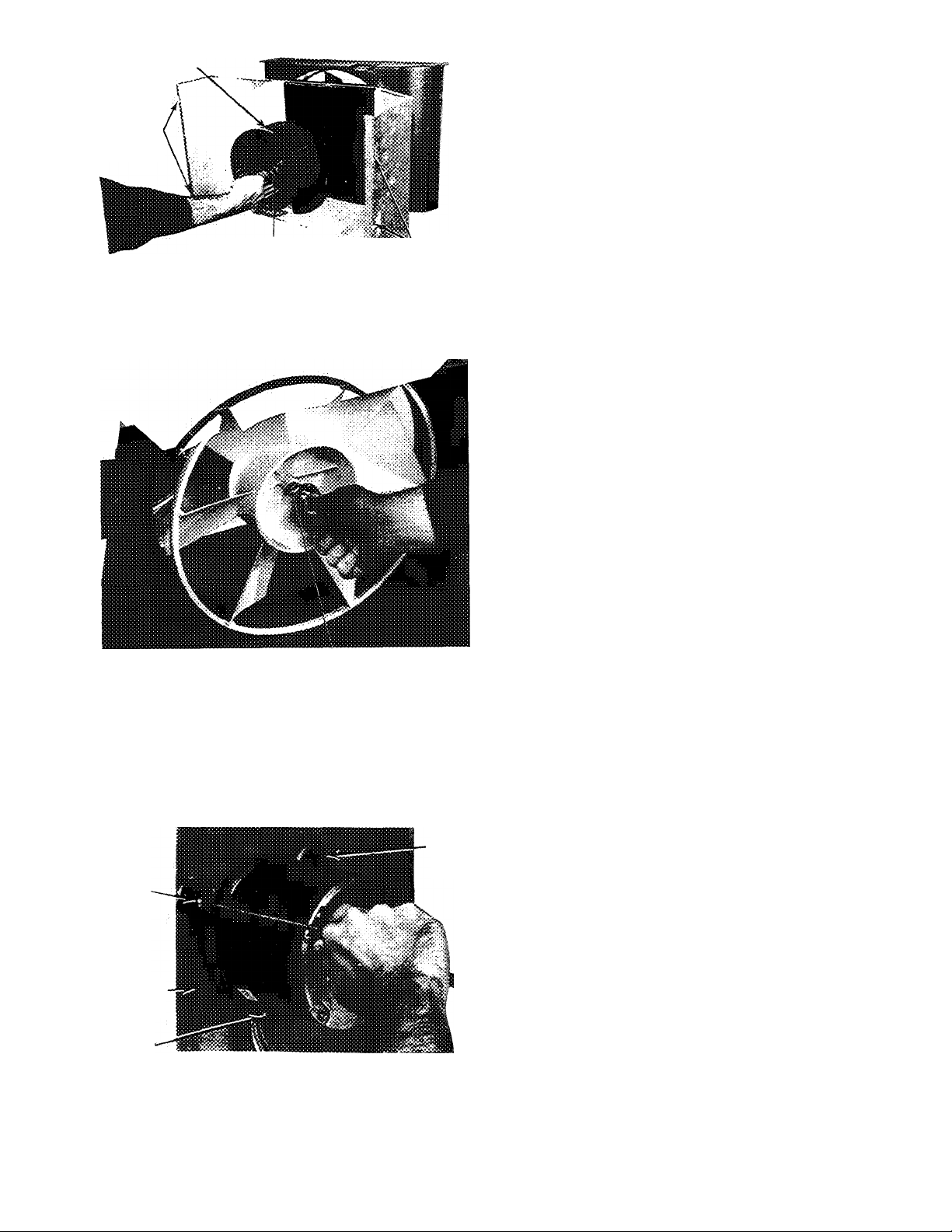
BLOWER WHEEL
PARTITIONSLOTS
3. Remove indoor blower wheel and outdoor fan. See
Indoor Blower Wheel Removal and Outdoor Propeller
Fan Removal instructions, page 10.
4. Remove control box. See Control Box Removal instruc
tions, page 5.
5. Carefully disconnect fan motor wiring.
6. Remove 3 screws securing motor to partition. See
Fig. 24.
7. Reverse above procedure for reassembly.
SPRING METAL
CLIP
PARTITION
SLOTS
Fig. 22 — Removing Blower Wheei
SPRING METAL CLIP
Fig. 23 — Removing Outdoor Propeiler Fan
Fan Motor Removal (See Fig. 24)
1. Remove chassis from casing. See Chassis Removal in
structions, page 8.
2. Remove air handling system. See Air Handling System
Removal instructions, page 9.
SCREW
SCREW
PARTITION
SCREW
Fig. 24 - Removing Fan Motor
Compressor Removal (See Fig. 15)
NOTE: Before removing compressor, refer to Service sec
tion, page 1, and Carrier Standard Service Techniques
Manual, Chapters 1 and 2.
1. Reclaim all refrigerant from system using a Carrier
Totalclaim® or Carrier Totalsave recovery system, or a
comparable refrigerant recovery system.
2. Remove chassis from casing. See Chassis Removal in
structions, page 8.
3. Remove compressor terminal cover. (See Fig. 15.)
4. Disconnect wires from compressor and external
overload protector terminals Label wires to aid in
reassembly.
NOTE: Some models may have compressors with inter
nal overload protectors.
5. Replace external overload protectors, if needed.
6. Disconnect piping. Refer to Compressor Replacement
section, page 2, being careful to observe all
CAUTIONS.
Strainer Removal and Replacement
NOTE: Two strainers are installed in the interconnecting
tubing: one is between the condenser and capillary tube,
and one is between the evaporator and capillary tube. (For
typical location, see Fig 21.)
1. Remove chassis from casing. See Chassis Removal in
structions, page 8.
2. Reclaim all refrigerant from system using a Carrier
Totalclaim or Carrier Totalsave recovery system, or a
comparable system. Refer to Service section, page 1.
3. Cut tubing 1 in. from capillary tube insertion point.
4 Use a thin piece of wire to remove strainer from tubing.
5. Insert new strainer into tubing Reassemble tubing with
field-supplied copper coupling.
Electric Heater Assembly Removal
1. Remove chassis from casing. See Chassis Removal in
structions, page 8.
2. Remove plastic access cover on top of partition. (See
Fig. 25.)
3. Remove heater assembly (Fig. 26) by lifting straight up,
taking care not to cause fin damage to top of evaporator
coil when heater assembly mounting bracket is lifted off
coil.
4. Remove 2 wires from heater assembly (Fig. 25). Mark
wires to aid in reassembly
5. Repair or replace limit switches (Fig. 26) as needed.
6. Reverse above procedure for reassembly.
11
Page 12
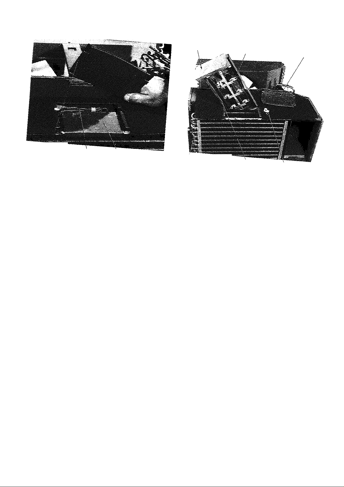
MOUNTING BRACKET
PLASTIC
access
COVER
WIRES (2,
'9- 25 Heater Assembly Wires
evaporator
Fig. 26 - rho» ■
H^TERWIRH
9 Chassis »i,h Elactn,! Haatar
12
c
Page 13

SERVICE POINTS
(Check Annually)
Clean evaporator and condenser coils.
1.
Indoors — Use a hooked wire or bristle brush to re
move dirt from fins.
Outdoors — Use compressed air or a vacuum cleaner.
Clean basepan and other painted surfaces.
Clean all drain passages.
3.
Clean motor and fans.
Vacuum clean the insulation.
5.
Paint parts that show evidence of rust with a good rust-
resistant paint.
7. Check refrigerant connections for evidence of leakage.
Repair if necessary.
8. Check wires for deterioration.
9. Check damper controls.
10. Fans should be tight on motor shaft.
11. Run the unit and eliminate any piping vibration.
12 Check thermostat capillaries for proximity to refriger
ant tubing (should not be touching). Check to be sure
protective sleeve is in place.
13
Page 14
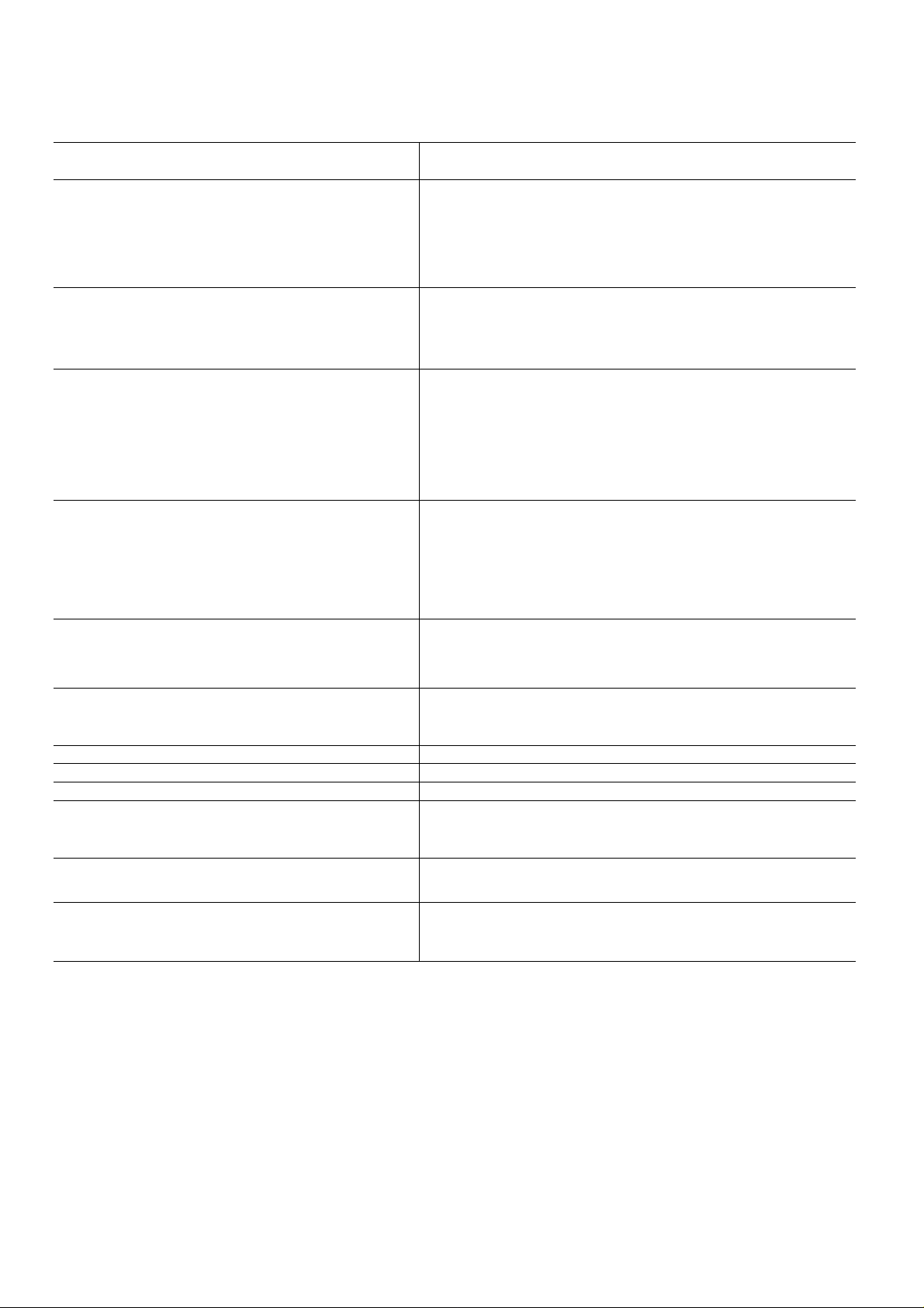
TROUBLESHOOTING
SYMPTOM AND
PROBABLE CAUSE
COMPRESSOR DOES NOT RUN
Opening in Power Circuit
1. Controi off
2. Biown fuse
3. Defective wiring
4. Defective service cord
5. Loose eiectricai connections
6. Faulty switches, thermostat, or fan
Compressor Power Supply Open
1. Loose leads at compressor terminals
2. Defective motor overload switch
3. Defective capacitor
4. Open compressor windings
5. Seized compressor
COMPRESSOR RUNS BUT CYCLES
Fan Operating Erratically
1. Loose lead at fan motor
2. Defective or burned out motor
3. Outdoor air restricted or recirculating
4. Overcharge or noncondensables in system
5. Restricted discharge line
6. Defective motor overload switch
Cycles on Compressor Overload
1. Defective run capacitor
2. Defective compressor bearings or valves
3. Greatly restricted indoor air (iced indoor coil)
4. Low refrigerant charge
5. Indoor capillary restricted
6. Liquid line restricted
7. Compressor hot
8. Weak or inconsistent line power
INSUFFICIENT COOLING
Cooling Air Not Adequate
1. Dirty filter or coil
2. Iced indoor coil (slightly low refrigerant charge)
3. Defective fan motor
Condenser Air Not Adequate
1. Outside air restricted
2. Dirty coil
3. Defective fan motor
Unit Undersized
Air Leakage
Capillary Restricted
Compressor Flooding
1. Unit overcharged
2. Low indoor airflow
AIR SWEEP NOT WORKING
1. Linkage in upper control box stuck
2. Air sweep motor failure
HEATER CYCLES ON LIMIT SWITCH
1. Dirty filter
2. Blocked indoor air inlet
3. Low airflow due to fan motor speed
PROBABLE REMEDY
1 Reset control button
2. Replace fuse.
3 Replace wiring.
4 Replace service cord
5. Tighten connections.
6. Replace defective component.
1 Tighten leads.
2. Replace switch
3 Replace capacitor
4 Replace compressor
5. Replace compressor
1. Tighten lead
2. Repair or replace motor
3. Check for dirty filter, proper clearances around unit —
remove any obstructions
4 Reclaim refrigerant, evacuate and recharge system according to
nameplate specifications.
5. Check for obstruction in line, replace tubing if required.
6 Replace switch.
1 Replace capacitor.
2. Replace compressor
3 Defrost indoor coil.
4 Add charge according to approved method.
5. Replace capillary.
6. Replace strainer
7. Verify refrigerant charge.
8. Check line voltage at time of compressor start-up
1. Clean as required
2. Recharge.
3. Replace fan motor.
1. Check for obstructions and dirty filter. Remedy as required.
2 Clean coil.
3. Replace fan motor.
Re-evaluate unit for proper capacity
Check caulking around sleeve Repair if necessary.
Replace capillary.
1 Reclaim refrigerant, evacuate and recharge system according to
nameplate specifications.
2 Clean filter and/or evaporator coil
1 Lubricate linkage. Check for proper assembly
2 Replace motor
1 Clean or replace filter
2 Remove blockage.
3 Check fan motor. Repair or replace as necessary.
14
Page 15

Copyright 1994 Carrier Corporation
Bookll 14 PC 131 Catalog No 537-320 Printed in U S.A Form 73X,Y-1SS Pg 16 3-94 Replaces: New
Manufacturer reserves the right to discontinue, or change at any time, specifications or designs without notice and without incurring obligations.
Tab |8a|10a
 Loading...