

Page 1

HEATING & COOUNG
Gas-Fired Induced-Combustion Water Boilers
Installation, Start-Up, and Operating Instructions
Sizes 042—225, Series 101
NOTE: AFFIX THESE INSTRUCTIONS ADJACENT TO THE
BOILER.
NOTE: Read the entire instruction manual before starting the
installation.
SAFETY CONSIDERATIONS
Installing and servicing heating equipment can be hazardous due to
gas and electrical components. Only trained and qualified person
nel should install, repair, or service heating equipment.
When working on heating equipment, observe precautions in the
literature, tags, and labels attached to or shipped with the unit and
other safety precautions that may apply.
Follow all safety codes. In the United States, follow all safety
codes including the National Fuel Gas Code NFPA No. 54-
1988/ANSI Z223.1-1988. Wear safety glasses and work gloves.
Have fire extinguisher available during start-up and adjustment
procedures and service calls.
Recognize safety information. This is the safety-alert symbol ^ .
When you see this symbol on the unit and in instructions or
manuals, be alert to the potential for personal injury,
Understand the signal word DANGER, WARNING, or CAU
TION. These words are used with the safety-alert symbol. DAN
GER identifies the most serious hazards which will result in severe
personal injury or death. WARNING signifies hazards that could
result in personal injury or death. CAUTION is used to identify
unsafe practices which would result in minor personal injury or
product and property damage.
These instructions cover minimum requirements and conform to
existing national standards and safety codes. In some instances,
these instructions exceed certain local codes and ordinances,
especially those that may not have kept up with changing residen
tial construction practices.
minimum for a safe installation.
Model 61SW is a low-pressure, sectional, cast-iron water boiler.
The design of model 61SW is certified by A.G.A. for use with
natural and propane gases (model 61SWC with natural gas and
61SWE with propane gas). It is tested for a maximum working
pressure of 50 psi on water in accordance with American Society
-of—Mechanical—Engineers-(A.S.M.E..)—Code_IM_Standards_for_
cast-iron boilers. It is to be installed indoors only. All boilers are
factory assembled.
“All installations are subjectTo Codes established by localTitiiities or
other authorities having jurisdiction. This jurisdiction normally
covers electrical wiring, gas piping, flue specification, and insula
tion of adjacent combustible material where required clearances
cannot be maintained. The installation must conform with the
National Fuel Gas Code, NFPA No. 54-1988/ANSI Z223.1-1988.
Where required by the authority having jurisdiction, the installa
tion must conform to the American Society of Mechanical Engi
neers’ Safety Code for Controls and Safety Devices for Automat
ically Fired Boilers, No. CSD-1.
We require these instructions as a
INTRODUCTION
61 sw
lama
Fig. 1—Model 61SW-075100
Consult the local building codes or ordinances that may apply.
INSTALLATION
£k CAUTION
Do not install the boiler in a corrosive or contaminated
"atmosphere. Make~sure~ all”combustion“and“circulating-air
requirements are adhered to, in addition to all local codes and
ordinances.
Do not use this boiler during construction when adhesives,
"sealersrand/or new carpets are being installed-If-lhe-boiler-is-
required during construction, use clean outside air for com
bustion and ventilation. Compounds of chlorine and fluorine
when burned with combustion àirïbim“aci3swKiclrwill cause
corrosion of the sections and metal vent systems. Some of
these compounds are found in paneling and dry wall adhe
sives, paints, thinners, masonry cleaning materials, and many
other solvents commonly used in the construction process.
Step 1—Location
1. The boiler must be installed on a level foundation. Metal
shims may be used to level if required. Locate the boiler near
a gas vent or a chimney.
A.S.M.E.
A85085
Manufacturer reserves the right to discontinue, or change at any time, specifications or designs without notice and without incurring obligations.
Book 1 4 PC 101
Tflh Iftalfta
Catalog No. 536-113 Printed in U.S.A.
Form 61S-2SI
pgi
10-92 Replaces: 61S-1SI
Page 2
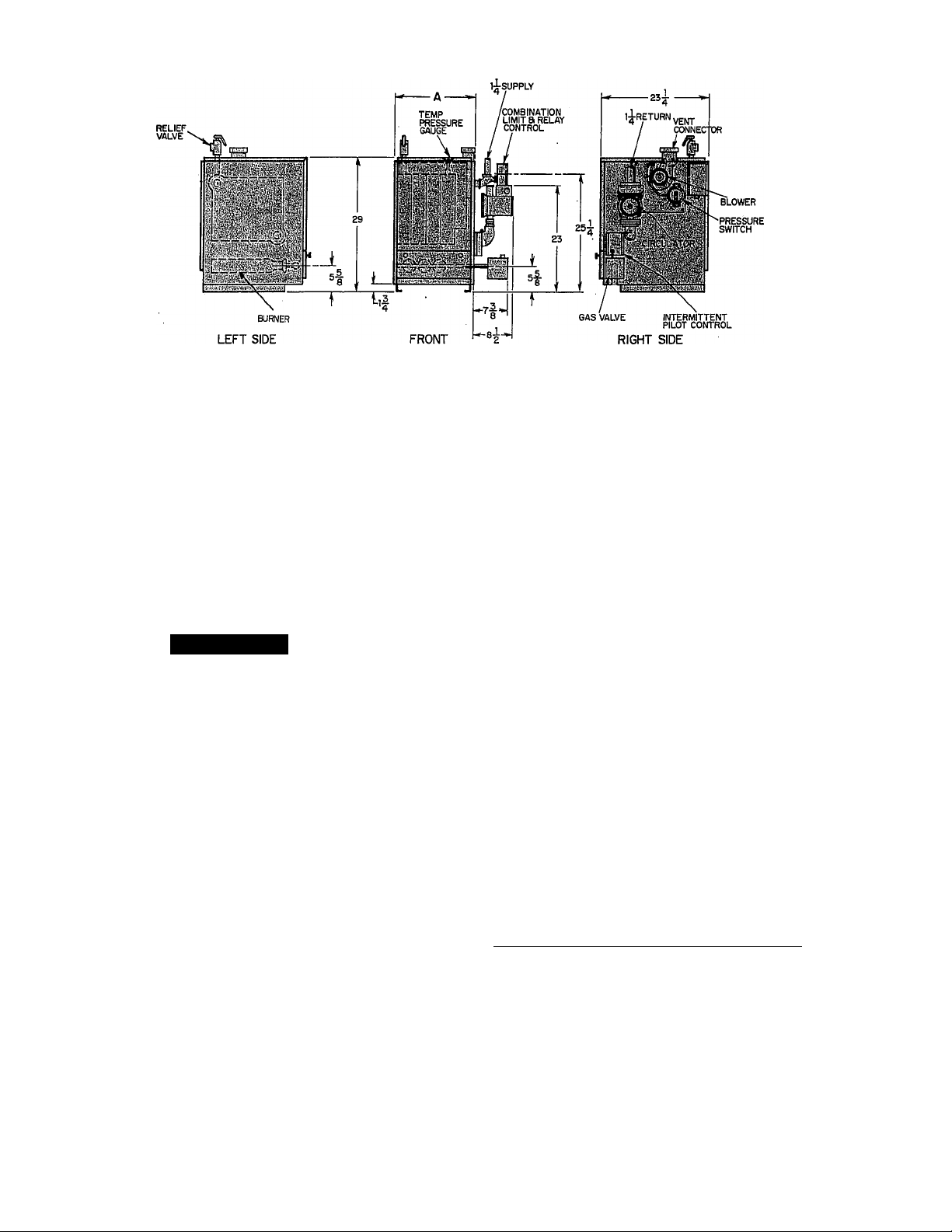
Fig. 2—Dimensional Drawing
A85084
2. Combustible floors-Do not install the boiler on carpeting.
When the boiler is installed on a combustible floor, you must
use a factory-supplied combustible floor installation kit con
taining a rectangular piece of insulation material. Position the
insulation on the combustible floor and place the boiler on top
of the insulation.
3. Alcove installation only — Maintain at least 6 in. from com
bustible material on the left-hand (LH) side, 6 in. from the
back and 6 in. from the top.
4. Leave enough room for service access on the right-hand (RH)
side and front. A minimum of 24 in. is required.
A WARNING
The boiler, when installed, must be electrically grounded in
accordance with the National Electrical Code, ANSI/NFPA
No. 70-1988.
Step 2—Air For Combustion and Ventilation
Table 2—Dimensions (In.)
MODEL
AND SIZE
61SW-042100
61SW-075100
61SW-112100
-etsw^rsoioo”
61SW-187100
61SW-225100
*With factory-supplied adaptor installed.
11
14-1/4.
17-1/2
■'20-3/4“
24
27-1/4
The relief-air supply must be in the same atmospheric pressure
zone as the combustion-air inlet supply to the boiler.
^^1 gas-fired equipment must'be'supplied^witlrthe airthat enters’
into the combustion process and is then vented to the outdoors.
Sufficient air must enter the boiler room to replace that air drawn
up the vent stack. Replacement air must be provided by means of
ducts from the outside to the boiler location or conditioned space.
Under all conditions, enough air must be provided to insure there
will not be a negative pressure condition within the boiler room or
space.
In the past, the infiltration of outside air assumed in heat loss
calculations (1 air change per hour) was assumed to be sufficient.
However, current construction methods using more insulation and
WA
VENT
CONNECTION
4*
4*
4*
■ 4*~
vapor barriers, tighter fitting and gasketed doors and windows or
weather-stripping, and mechanical exhaust fans now require the
positive introduction of outside air.
The requirements for combustion and ventilation air depend upon
whether the boiler is located in a confined or unconfined space.
An unconfined space is defined as a space whose volume is not
less than 50 cu ft per 1000 Btuh of the total gas input rating of all
appliances installed in that space.
Advise the owner of the necessity for keeping air passages to the
boiler area free of obstructions. This clearance is necessary so
combustion air can enter freely into the combustion chamber. It is
also necessary to provide adequate ventilating air.
EQUIPMENT LOCATED IN CONFINED SPACES
1. All Air From Inside Building
The confined space shall be provided with 2 permanent
openings communicating directly with an additional room(s)
of sufficient volume so that the combined volume of-all spaces
meets the criteria for an confined space. The total input of all
gas utilization equipment in the confined space shall be
considered in making this determination. Each opening shall
have a minimum free area of 1 square in. per 1000 Btuh of the
total input rating of all gas utilization equipment in the
confined space, but not less than 100 square in. One opening
shall be within 12 in. of the top and 1 within 12 in. of the
bottom of the enclosure. (See Fig. 3.)
—2wUl-Air-FTom-Outdoors
--------------------------^---------------------------
The confined space shall be provided with 2 permanent
openings, 1 within 12 in. of the top and 1 within 12 in. of the
bottom of the enclosure. The openings shall communicate
directly, or by ducts, with the outdoors or spaces (crawl of
attic) that freely communicate with the outdoors.
a. When directly communicating with the outdoors, each
-^^opening^shall-have-a-minimumTreerareamf-l-square-in-per=
4000 Btuh of total input rating of all equipment in the
enclosure. (See Fig. 4.) Use F and G.
b. When communicating with the outdoors with vertical
ducts, each opening shall have a minimum free area of 1
square in. per 4000 Btuh of total input rating of all
equipment within the enclosure. (See Fig. 4.) Use D and E.
c. When communicating with the outdoors with vertical
ducts, each opening shall have a minimum free area of 1
square in. per 2000 Btuh of total input rating of all
equipment in the enclosure. (See Fig. 4.) Use A and B or A
and C.
Page 3

Table 1—Ratings and Capacities
MODEL
AND
SIZE
TYPE
Max Input Btuh
61SW-042100 Water 42,500 36,000
61SW-075100
Water
75,000 63,000
61SW-112100 Water 112,500
61SW-150100
Water
150,000 125,000
61SW-187100 ■ Water 187,500
61SW-225100 Water
‘The above gas inputs are certified for altitudes to 2000 ft.
are computed at 150 Btuh/sq ft.
The seiection factors providing for piping loss and starting
are based on an allowance of 1.15.
tin accordance with U.S. Government test procedures.
225,000 186,000
RATINGS*
For elevations above 2000 ft, reduce input 4 percent for each 1000 ft above sea level. Ratings in square ft
load are those recommended by the Institute of Boiler and Radiator Manufacturers. Net water boiler ratings
ill 12
I
___
= 1 SQ. INCH
•=• PER 1000
= BTUH
Heating Capacilyf
Btuh
94,000
155,000
12 MAX
i
RATINGS
Sq Ft
240
Btuh Sq Ft
31,000
420 55,000
620 82,000
827 109,000
1033 135,000
1240 162,000
Г'
12 MAX
1 so. INCH PER
2000 BTUH
NET
BOILER WATER APPROX
CAPACITY IN
GALLONS WEIGHT
207 1.75
367
547
727
3.00 263
4.25 320
5.50 369
900 6.75 426
TO VENTED
ATTIC
:i
1080
TO ROOF
¡1 so. INCH PER
4000BTUH
8.00 476
DUCTS
1 SO. INCH PER
SHIPPING
211
4000BTUH
VENT
TO ROOF
^=-1 SO. INCH
PER 1000
I^BTUH
____L____L____
L_.
12 MAX
A90060
Fig, 3—Air From Inside Building
d. When ducts are used, they shall be of the same cross-
-----------
“EQUIPMENT LOCATED IN ÜT^CONFÎNËD SPACÈS
seetional-area-as-the-free-area-of-the-openings-to-which-they“
connect. The minimum diniension of rectangular air ducts
shall not be less than 3 in.
An unconfined space is defined as a space whose volume is not
less than 50 cu ft per 1000 Btuh of the total gas input rating of all
appliances installed in that space. Rooms communicating directly
with the space in which the appliances are installed, through
openings not furnished with doors, are considered part of the
unconfined space.
In unconfined spaces in buildings, infiltration may be adequate to
provide air for combustion, ventilation, and dilution of flue gases.
However, in buildings of tight construction (weather stripping,
heavily insulated, caulked, vapor barrier, etc.), additional air may
need to be provided using the methods described in section,
“Equipment Located in Confined Spaces.”
VENT
TO ROOF
DUCTS TO
OUTSIDE
1 SQ. INCH PER
2000 BTUH
.
12 MAX
_________
—;гт~7'
[.
12 MAX
L-
I so. INCH PER
4000BTÜH:—
TO VENTED
CRAWL .rn
RPACF DUCT TO
OUTSIDE
-------------------
Fig*-4—Air-From-Outdoor
LOUVERS, GRILLES, AND SCREENS
-In-calculating-the^ee-arear'Consideration“shall~be“given“tO“the“
blocking effect of louvers, grilles, or screens protecting openings.
Screens used must not be smaller than 1/4-in. mesh. If the free area
through a design of louver or grille is knotvn, it should be used in
calculating the size opening required to provide that free area
specified. If the design and free area is not known, it may be
assumed that wood louvers will have a 20- to 25-percent free area
and metal louvers and grilles will have a 60- to 75- percent free
area. Louvers and grilles that provide combustion and dilution air
must be constructed so they cannot be closed.
Step 3—Water Line Connection
For water-type boilers with the circulator pump mounted on the
RH side, the water outlet (supply to system) must be on the RH
liso. INCH PER
) 2000 BTUH
------------------
A90059
Page 4

Table 3—Fresh Air Duct Capacities for Tightly
Sealed Houses*
FRESH AIR
DUCT SIZE
(IN.)
3 X 12
8x8
8 X 12
8-1/2 X 16
‘Based on opening mesh soreen, or metal louvers.
1/4-MESH
SCREEN
(BTUH)
144,000
256,000
384,000
512,000 128,000
WOOD
LOUVERS
(BTUH)
36,000
64,000
96,000
FRESH
METAL
LOUVERS
(BTUH)
108,000
192,000
288,000
384,000
^AIR
DUCT
FRESH AIR DUCT
FOR TIGHTLY
SEALED HOUSE
Fig. 5—Fresh Air Duct for Tightly Sealed Buildings
side. (See Fig. 6.) Any other piping method will short-circuit water
flow through the boiler and insufficient heat will result from the
premature limit control cutout. When a boiler is installed on an
oversized piping system (a typical example is replacement of a
gravity boiler with a forced circulation boiler) and piping or
radiation are not changed, an adjustable flow control valve or
square head cock must be added to reduce the water flow through
the boiler. This allows proper water temperature (160° F mini
mum) to be obtained which eliminates continuous condensate on
the sections. If more than 1 return is used, use a flow control valve
or square head cock in each return. (See Fig. 6.)
RETURN
BOILER
A90065
SUPPLY
exposed to refrigerated air circulation, the boiler piping system
must be equipped with flow control valves or other automatic
means to prevent gravity circulation of the boiler water during the
cooling cycle.
A84191
Fig. 7—Piping With Refrigeration System
Step 5—Gas Piping
The gas supply line should be a separate line directly from the
meter to the boiler, if possible. Refer to Table 4 for the recom
mended gas pipe sizing. Do not use cast-iron or galvanized pipe.
For additional information, refer to “National Fuel Gas Code”
NFPA No. 54-1988/ANSI Z223.1-1988.
Table 4-Gas Pipe/Tubing Capacity
NATURAL GAS
Iron Pipe—Btuh Input
(Ft)*
20
40
60
1/2 in.
92,000 190,000
63,000
50,000
3/4 in.
130,000 245,000
105,000 195,000
PROPANE GAS
Length
(Ft)*
20
40 . 90,000
60 72,000
‘The length of pipe or tubing should be measured from the gas meter or
propane second stage regulator.
Copper Tubing—OD
5/8 in.
3/4 in.
131,000 216,000 189,000
145,000
121,000
1 in. 1-1/4 in.
350,000
625,000
445,000
365,000
Iron Pipe
-1/2 in. 3/4 in.
393,000
129,000
103,000
267,000
217,000
FLOW CONTROL VALVE
SQUARE HEAD COCK
OR
A84190
Fig. 6—System Water Line Connection
Step 4—Boiler With Refrigeration System
When a water boiler is used in connection with a chilled-water
system, it must be installed so that the chilled medium is piped in
parallel with the heating boiler with appropriate valves to prevent
the chilled medium from entering the heating boiler. An example
of such piping is shown in Fig. 7. When the boiler is connected to
heating coils located in air handling units where they may be
"liTOidTow spbfriiTlohgTTihTbf piperld's'best to'^slope all pipeTiyA--
in. every 15 ft to prevent traps. All horizontal runs should slope
away from the meter to risers. Risers should be used to connect to
the boiler and to the meter.
Joint compounds (pipe dope) should be applied sparingly and only
to the male threads of the joints. Consult your local supplier for the
-type-of-compound-to.-berusedzThisTpipe-dQp.ermusl-be-resistant-tothe action of propane gas.
Install a sediment trap in the riser leading to the boiler. This
sediment trap will serve as a trap for dirt or condensate. This
sediment trap can be installed by connecting a tee to the riser
leading to the boiler, so that the straight-through section of the tee
is vertical. Then, connect a capped nipple into the lower end of the
tee. The capped nipple should extend below the level of the gas
controls. (See Fig. 8.)
When a gum filter is required by local codes, install it in
accordance with their requirements.
Page 5

An accessible manual shutoff valve shall be installed upstream of
the gas controls and within 5 ft of the gas boiler.
Place a ground joint union between the gas control manifold and
the manual gas shutoff valve, or use an approved flexible or
semi-rigid conductor.
Support all piping with the appropriate straps, hangers, etc. (1
hanger every 10 ft minimum).
Piping should be pressure tested before any appliance or shutoff
valve has been attached, in accordance with the requirements of
the local plumbing or gas code.
if the pressure exceeds 0.5 psig (14-in. wc), the gas supply pipe
must be disconnected from the furnace before the pressure test. If
the test pressure is equal to or less than 0.5 psig (14-in. wc), close
the manual shutoff valve located on the gas valve before the test.
If is recommended that the ground joint union be loosened before
pressure testing.
3. If venting into a masonry chimney without a liner, line
chimney from top to bottom with either:
a. listed Type-Bl vent pipe
b. listed flexible vent liner
c. poured ceramic liner
4. Outside chimneys should not be used unless they are either:
a. enclosed in a chase
b. lined with Type-Bl vent pipe
5. The vent connector from the boiler to the chimney should run
as directly as possible with as few elbows as possible.
6. The vent connector from the boiler to the chimney must be
4-in. pipe. The boiler’s induced-draft blower has a 3-in. outlet.
A 3- X 4-in. adaptor fitting is included in the parts bag. Locate
the adaptor fitting on the outlet of the induced-draft blower,
and ensure it is gastight with a bead of the furnished silicone
‘ sealant.
The boiler installation for chimney venting is not complete
unless the 3- x 4-in. adaptor fitting is located and secured.
7. Where possible, it is recommended to common vent the water
heater and boiler. Each appliance must have its own vent
connector. The 2 vent connectors at the chimney must be kept
at least 6 in. apart. (See Fig.'9.)
A WARNING
-Never-puige-aJine_intQ_a combustion chamber. Never use
matches, candlesrflameror-other-sources-of-ignition-forahepurpose of checking leakage. Use a soap-and-water solution
to check for leakage. After all connections have been made,
purge the lines and check for leakage.
Step 6—Venting
-This-is a-very-important-par.t-of_your heating system. It must be
clean, the right size, properly constructed and in GOOD CONDI
TION.
1. Use local codes for installation or National Fuel Gas Code,
NFPA No. 54-1988/ANSI Z223.1-1988. It is very important to
properly size the venting system for induced-draft appliances.
Consult the New Vent Sizing Tables, available from A.G.A. or
Venting Tables Category I Central Furnaces, available from
Gas Appliance Manufacturers Association (GAMA) for cor
rect sizing information.
2. These are high-efficiency boilers with a low stack or exhaust
temperature.
Fig. 9—Type»B1 Venting Through the Roof
—8.-Tf-the-hoiler is the only appliance connected to thejyejihj^ype^
B1 vent pipe is recommended for the vent connector.
9. Slope pipe up from boiler to chimney 1/4 iii. per ft.
10. End of vent pipe must be flush with the inside face of the
chimney flue. Use a sealed-in thimble for the chimney
connection.
11. 'The sections ofVenf’p^ipfrsIiouId'be'fastened'with-sheet-raetalscrews to make the piping rigid. Use stovepipe wires to
support the pipe from above.
12. Do not connect to fireplace flue.
13. Do not install a damper on this boiler.
MINIMUM VENT PIPE CLEARANCE
If the vent pipe must go through a crawl space, Type-Bl vent pipe
should be used. Where vent pipe passes through a combustible
wall or partition, use a ventilated metal thimble. The thimble
should be 4 in. larger in diameter than the vent pipe.
Page 6

If boiler is installed with single wall vent, it must have a 6-in.
clearance between its surface and any combustible material. A new
Type-Bl vent pipe or flexible liner must be installed in accordance
with the instructions furnished with the vent.
Check the vent pipe to see if it is firestopped where it goes through
the floor or ceiling. It should have an approved vent cap with
clearances from the roof as shown in Fig. 9. If clearances are less
than shown in Fig. 9, have the vent checked by local authorities.
- LINER
- CHIMNEY
A92406
Fig. 10—Venting Boiler Into Masonry Chimney
For boilers connected to gas vents or chimneys, vent installations
shall be in accordance with Part 7, Venting of Equipment, of the
National Fuel Gas Code, ANSI Z223.1-latest issue and applicable
provisions of the local building codes.
Vent connectors serving appliances vented by natural draft shall
not be connected into any portion of mechanical draft systems
operating under positive pressure.
The induced-combustion boiler can be common vented with a
water heater. (See Fig. 11.)
REMOVAL OF EXISTING BOILER FROM COMMON VENT
SYSTEM
1. In replacement installations where an existing vent system
may be used, inspect the vent system for condition, size, type
of material, and height to meet the appliance application
requirements. If it is oversized, condensation could corrode
the venting system. Installation of a new venting system may
be required.
2. When removing an existing boiler from a venting system
serving other appliances, the vent system is likely to be too~
large to vent the remaining attached appliances properly.
The following steps shall be followed with each appliance
remaining, connected to the common venting system placed in
“operation7while-the"otherappliances-remaining-connected-to-
the common venting system are not in operation:
a. Seal any unused openings in the common venting system.
b. Visually inspect the venting system for proper size and
horizontal pitch and determine there is no blockage or
restriction, leakage, conosion and other deficiencies which
could cause an unsafe condition.
c. Insofar as is practical, close all building doors and windows
and all doors between spaces in which appliances remain
ing connected to the common venting are located and other
spaces of the building. Turn on clothes dryers and any
appliance not connected to the common venting system.
Turn on any exhaust fans, such as range hoods and
bathroom exhausts, so they will operate at maximum speed.
Do not operate a summer exhaust fan. Close fireplace
dampers.
d. Follow the lighting/operating instructions. Place the appli
ance being inspected in operation. Adjust thermostat so
appliance will operate continuously.
e. Test for spillage at the drafthood relief opening after 5
minutes of main burner operation using the flame of a
match or candle.
f. Mter it has been determined that each appliance remaining
connected to the common venting system properly vents
when tested as outlined above, return doors, windows,
exhaust fans, fireplace dampers and any other gas-burning
appliance to their previous conditions of use.
g. If improper venting is observed during any of the above
tests, the common venting system must be corrected. The
vent system or vent connectors may need to be resized
-----
according-to-these-instruetions-to-approaeh-the-minimum—
sizénñsiñgfKeTppWpfiáté^GAMA'Vehting Tables7Paft 7 bf~
the National Fuel Gas Code NFPA 54-1988/ANSI Z223.1-
1988.
-ELECTRICAL-
IMPORTANT: Before proceeding with the electrical connections,
make certain the volts, hertz, and phase correspond to that
specified on the boiler rating plate. -
The specific unit Installation Instructions contain wiring diagrams
which show the proper field high- and low-voltage wiring. Make
all connections in accordance with the National Electrical Code
and any loeal codes or ordinances that might apply.
The boiler, when installed, must be electrically grounded in
accordance with the National Electrical Code, ANSI/NFPA No.
70-1990.
A permanent, separately fused electrical power supply, complete
with manual disconnect switch, must be provided for this unit.
Page 7

If a manual disconnect switch is to be mounted on the appliance,
select a location where a drill or fastener will not contact electrical
or gas components.
NOTE: Use only copper wire between the disconnect switch and
the unit.
Check all electrical connections (both factory and field) for
tightness. Recheck tightness of electrical connections after the unit
has reached operating temperatures.
Step 1—Filling The Boiler
Check to be sure that all connections have been made. Before
atternpting any operations, fill the system with water.
A CAUTION
I Never light a burner under an empty boiler.
1. Close air vents on all radiation units,
2. Open water supply valve on each radiation unit.
3. Close drain cock and air bleed screw on boiler expansion tank.
4. Open valve in line from boiler to expansion tank.
5. Open water inlet valve to boiler and leave open.
6. Starting with lowest radiation unit, open air vent.
7. Working from the lowest to the highest radiation unit, repeat
item 6 until you have vented every radiation unit in the
system.
NOTE: Systems with an automatic vent on each radiation unit
will not require manual venting.
8. Check temperature/pressure gage. It should read between 10
and 15 psig.
9. Check system piping connections for leaks.
START-UP AND ADJUSTMENTS
NOTE: Safe lighting and other performance criteria were met
with the gas manifold and control assembly provided with the
boiler when it underwent testing as specified in ANSI Z21.13b-
1991.
Check to be sure that all connections have been made. Before
attempting any operation, fill thé system with water. For steam
boilers, fill to the water line. Never light a burner under an empty
boiler.
CHECK PILOT TO BE SURE THAT ALL CONNECTIONS
HAVE BEEN PROPERLY MADE.
Light the pilot, using the procedure outlined on the lighting
instruction plate attached to the boiler.
___________________
A CAUTION
The boiler is equipped with an intermittent-type ignition
device that functions during each thermostat on cycle. DO
NOT USE MATCH OR OTHER OPEN FLAME TO LIGHT
-pilot:
flame should not touch the boiler section. If the pilot flame
does not have the appearance as described, it can be adjusted.
a. The gas valve is equipped with an adjustable screw.
Remove capscrew to expose adjustable screw. Turn screw
until flame has desired appearance.
b. Replace capscrew.
A WARNING
The boiler is equipped with an intermittent ignition device
(IID). Check the safety pilot operation as follows; Attach a
low-voltage test light to the electrical leads of the gas valve at
terminals marked 1 (or TH) and 2 (or TR). With the
thermostat set above room temperature (pilot and main
|
burners operating), turn OFF the gas supply to burners and
pilot with main shutoff valve. If the test light goes out within
45 sec, the safety pilot is functioning properly. If the light
, does not go out within 60 sec, replace the safety pilot. Place
the boiler in normal operation by following the lighting
instructions on the boiler.
GAS INPUT-DETERMINE THE GAS INPUT
1. Natural gas
a. Turn off all other gas appliances and pilots.
b. Measure time (in sec) for gas meter test dial to complete 1
revolution.
c. Refer to Table 5 for cu ft of gas per hr.
d. Multiply cu ft/hr X heating valve' of gas. Obtain heating
valve of gas from local gas utility.
EXAMPLE: .
Btu heating input = Btu/cu ft x cu ft/hr
Heating value of gas = 1070 Btu/cu ft
Time for 1 revolution of 2-cu ft dial = 72 sec
Gas rate = 100 x 1070 = 107,000 Btuh
e. The measured gas input should not exceed the gas input
shown on the unit rating plate.
f. Observe manifold pressure. It should be adjusted to read
3.5- ±0.3-in. wc. Adjust pressure by using an adjusting
screw in the gas pressure regulator stem. (This screw is
concealed under the regulator sealing cap.) Turn screw
clockwise to increase pressure and counterclockwise to
decrease pressure.
-Small-changes~ihHnput-can-be-made--by-changing-the-manifold“
pressure as previously described. However, the manifold pressure
should not vary more than 0.3-in. wc from the rated pressure.
A further change in gas rate can be accomplished, if necessary due
to high altitude, by changing the fixed orifice at the burners.
___________________________
1. If the gas supply line was not purged before connecting the
^^=^boilerrit‘will“be~full'of'aii77'is'it"would'talce^long time to vent
this air through the small pilot port, it is recommended that
pilot supply line be disconnected and be allowed to purge until
the odor of gas is detected. Never purge gas lines into the
combustion chamber. Iinmediately upon detection of gas
odor, reconnect pilot supply tube. Allow 5 minutes to elapse,
then light pilot using the procedure outlined on the lighting
instruction plate attached to the boiler.
2. The pilot flame should be soft blue in color and should be
checked periodically. The flame lies under the carryover ports
■ of burners and merges with the carryover flames. The pilot
A CAUTION
I Do not under any circumstances redrill orifices.
2. Propane gas models
a. These units are equipped with pressure regulators. The
burner orifices are sized to give rated input at a manifold
pressure of 10-in. wc. Check manifold pressure and, if
necessary, adjust pressure.
3. High altitude ratings are approved for altitudes to 2000 cu ft
for all gases. Ratings for altitudes over 2000 ft are 4 percent
less for each 1000 ft above sea level.
________________
Page 8

Table 5—Gas Rate Cu Ft/Hr
SECONDS
FOR 1
REVOLUTION
10
11
12
13
14
15
16
17
18
19
20
21
22
23
24
25
26
27
28
29
30
31
32
33
34
35
36
37
38
39
40
41
42<
43
44
45
46
47
48
49
SIZE OF TEST DIAL
2
1
cu.ft
cu ft
360 720 1800
327 655 1636 51
300 600
277 555
514
257
240 480
450
225
424
212
200 400 100
189
180 360 900
171
164
157 .
150 300 750
144 288
138
133
129 257
124 248
120 240 600
116 232
113 225
109 218 545 86
106 212 529
103
100 200
97 195
95
92 185
90
88
86
84
82 164
80
78
76
75
73
1059
379 947
343 857
327 818 64
313 783 66
277.
267
, 643 76
621 78
581 82 44
563
206
514 90
500 92
466 94
189 474
462 98 37
180
450 100 36
176 439 102 35 71 .
172 429 104
167 419 106 34
409 108
160 400 110
157- 391 112 32
153 383 116 31
150 375 120 30
147 367
SECONDS
FOR 1
5
REVOLUTION
cu ft
50
1500 52 69
1385 53
1286
1200 55
1125 56
720 70 51
692
667
54
57
58 62 124
59
60
62 58
68 53
72 50
74 48 97
80 45
84
88 41
96 ■ 38
MAIN BURNER FLAME — The main burner flame should be
clear blue, almost transparent, with a well-defined inner cone. If
there is too much primary air, the flame will be well defined, but
with a tendency to float or lift off the burner ports. (See Fig, 12.)
OUTER MANTLE
OUTER CONE
INNER CONE
SIZE OF TEST DIAL
1
2 5
cu ft
cu ft
144
72
71
141 355
136 346
68 136
67
133 333
65 131 327
64 129
63 126 316
61 122
60 120 300
116 290
56
112 281
54
109 273
106 265
103 257
100 250
47
95
46 92
90 225
88 220
43
86
42
84 209
62 205
40
80 200
39 78 196
38 76 192 ■
75 188
74 184
72 180
35 69’ 173
33 67 167
33 65
.178 ■
68 170
64 161
62 155
60 150
A86002
Fig. 12—Proper Flame Appearance
____
IHERM.QS.TAT-HEAT=ANTIGIPATQR-GHEGK--------------------------^------The thermostat heat anticipation must be set to match the amp
draw of the gas valve and electrical components in the R-W circuit.
cu ft
360
340
321
310
305
243
237
231
214.
164
THEHHOSTAT y I
TERMINALS
---------
H ® ® ® © I
HOOK-AROUND
VOLT/AMMETER
10 TURNS AROUND JAWS
= 0.5 AMPS FOR THERMOSTAT SETTINO
A80201
Fig. 13—Amp Draw Check With Ammeter
CARE AND MAINTENANCE
A CAUTION
Because of possible damage to the equipment or personal
injury, maintenance should be performed by qualified persons
' only.
A WARNING
Never store anything on, or in contact with, the boiler, such
as;
Spray or aerosol cans, rags, brooms, dust mops, vacuum
cleaners, or other cleaning tools.
Soap powders, bleaches, waxes, or other cleaning com
pounds, plastic or plastic containers, gasoline, kerosene,
cigarette lighter fluid, dry cleaning fluids, or other volatile
fluids.
Paint thinners and other painting compounds, paper bags, or
other paper products.
For continuing high performance, and to minimize possible
equipment failure, it is essential that periodic maintenance be
performed on this equipment. Consult your local dealer as to the
proper frequency of maintenance and the availability of a mainte
nance contract.
The ability to properly perform maintenance on this equipment
-requires-eertain-mechanical-skills-and'toolsrlfyoTTdoTiot possess'
"these skiliraiidlodls, contact'your dealer for maintenance.
A WARNING
Turn OFF gas and electrical supplies to the unit before
performing-any maintenance or service. Follow the relighting
instructions ou-the-plate-attached-to-the-boileri
--------------------
—
terminals R and W. Fig. 13 illustrates an easy method of obtaining
the actual amp draw. The amp reading should be taken after the
pump motor has started.
FLUE PASSAGES — Flue passages between the sections should
be examined yearly and cleaned as required.
BOILER CONTROLS — Check all boiler controls for proper
operation at the start of each heating season. If the boiler is
operated year-round, check the controls at least every 6 months.
DRAINING BOILER — Do not drain the boiler between heating
seasons. In fact, the boiler should never be drained, flushed, or
boiled out unless it is absolutely necessary.
LEAKAGE — Make certain that there is no leakage in the system
at any time.
Page 9

FLUE — Inspect the flue connection and chimney annually to
make sure they are in good condition and have not become
obstructed.
CIRCULATOR SYSTEM LUBRICATION ' - The circulator is a
water self-lubricating type and does not require any further
lubrication.
Step 1—Cleaning The Boiler
1. Remove burner access door.
2. Remove burners and pilot.
3. Remove vent pipe.
4. Remove top panel and swing aside.
5. Remove flue collector.
6. Use flexible handle wire brush to clean passageways. (See Fig
14.)
7. Using vacuum cleaner with soft brush attachment, clean
burners. After cleaning, reinstall burners and pilot.
8. Reassemble boiler.
A66289
Fig. 14—Cleaning Boiler Passageways
Page 10

LINE-TO-LINE WIRING DIAGRAM
If any of the original wire as supplied with the boiler must be replaced, it must be replaced with the same type wire or its equivalent.
o
TJ
>
o
3]
m
3J
o
TJ
=. (O
3. a
œ A«
5‘
C •
Ò) d:
> i
3 ?
w
IÒ
CO
<5 â
-
X (O
fi> íL
o —
o (Q
2
4^
HOT
PRESSURI
SWITCH
INTERMITTENT
PILOT CONTROL
NEUTRAL
TO GAS VALVE
NEUTRAL
HOT _
FUSED
DISCONNECT
120/60/1
POWER SUPPLY
PRESSURE
swrrcH
24-V THERMOSTAT
L8148A AQUASTAT
DRAFT INDUCER
] AT 140C TRANSFORMER
S’ ^
Û > -5,
iiaOw S
B
^ of
ROLLOUT
SWITCH
VR8204A/VR8304M
GAS VALVE
5i 6
G
--------
UNE-VOLTAGE WIRING
--------
LOW-VOLTAGE WIRING
--------
LOW-VOLTAGE FIELD WIRING
B - BLACK
BT - BLACK WITH TRACER
W-WHITE
G - GREEN
R - RED
O- ORANGE
INTERMITTENT PILOT
bC
oc
CONTROL
á
S8600F - NATURAL GAS
to
S8600M - NATURAL OR
TO PILOT
pv
MV;PV
MV
PROPANE GAS
Fig. 15—Boiler Wiring Diagram
A92408
 Loading...