

Page 1

5F,H
HEATING A COOLING
Open-Drive Compressors
• Installation, Start-Up and Service Instructions
CONTENTS
Page
SAFETY CONSIDERATIONS .................................. 1
INSTALLATION
Step 1 — Prepare for Installation
.......................................................
............................
I
• PREPARE EQUIPMENT ROOM
Step 2 — Receive Machine
.....................................
• BEFORE UNLOADING
• RIG UNIT CAREFULLY
Step 3 — Install Unit
..............................................
10
• TO MOUNT MOTOR ON BASE
• TO MOUNT CARRIER COMPRESSOR UNITS
AND CONDENSER PACKAGES
• TO MOUNT COMPRESSOR BASE ON
SUPPORT STANDS
Step 4 — Assemble Refrigerant Piping
and Components.................................................... 10
• COMPRESSOR DISCHARGE PIPING
• REFRIGERANT DRIER
• FELT FILTERS
Step 5 — Install Multiple Compressors
................
11
• EQUALIZING LINES
Step 6 — Make Electrical Connections
................
II
• GENERAL NOTES
• ATTACH POWER WIRES TO COMPRESSOR
MOTOR
• CHECK MOTOR ROTATION
• INSTALL CRANKCASE HEATER
Step 7 — Check Compressor/Motor
Alignment............................................................ 13
• BELT DRIVE
• DIRECT DRIVE
• HOT CHECK AND DOWELING
Step 8 — Assemble Water Piping
Step 9 — Prepare Lubrication System
........................
.................
13
13
• INSTALL OPTIONAL EQUIPMENT
• CHECK OIL LEVEL
PREPARE FOR INITIAL START-UP....................... 13
Evacuate, Dehydrate, and Leak Test
...................
13
Refrigerant Charging ............................................ 13
START-UP............................................................... 13
Preliminary Steps
..................................................
13
Start Compressor................................................... 14
Check Control Operation
.....................................
14
Check High-Pressure Switch................................ 14
Check Low-Pressure Switch
...............................
14
Adjust Capacity Control (if required)................... 14
SCHEDULED MAINTENANCE............................... 17
Check Lubrication System
...................................
17
Check Water-Cooled Heads.................................. 19
SERVICE INSTRUCTIONS
Service Notes
.........................................................
Lubrication System
Pressure-Relief Valves
Suction Strainer
.....................................................
Cylinder Head and Valve Assemblies
.....................................
...............................................
..........................................
..................
19
19
19
26
26
27
Cylinder and Unloader Sleeves............................ 27
Connecting Rods and Pistons
Capacity Control Operation
.............................
..................................
28
28
1
1
Capacity Control Inspection and Service
Crankshaft Inspection and Service
Pump-End Main Bearing
............................................
.........................
Center Main Bearing.................................................... 33
Seal-End Main Bearing
..............................................
Crankshaft Seal Inspection and
Replacement.............................................................. 34
TROUBLESHOOTING
.................................................
SAFETY CONSIDERATIONS
Installation, start-up and servicing of this equipment
can be hazardous due to system pressures, electrical
components and equipment location.
Only trained, qualified installation and service per
sonnel should install, start-up or service this equipment.
When working on this equipment, observe precautions
in the literature, tags, stickers and labels attached to the
equipment and any other safety precautions that apply.
• Follow all safety codes.
• Wear safety glasses and work gloves.
• Use care in handling, rigging and setting bulky
equipment.
A WARNING
Before performing service or maintenance operations
on unit, shut off and tag main power supply to unit.
Electrical shock could cause personal injury.
INSTALLATION
Step 1 — Prepare for Installation
PREPARE EQUIPMENT ROOM — Locate compres
sor or condensing unit in a well-ventilated area. If natural
ventilation is inadequate, provide forced ventilation
through ductwork. Check applicable code requirements.
Provide freeze-up protection for water-cooled con
densers, water lines and accessories if freezing tempera
tures can occur during winter shutdown periods.
Provide sufficient clearance for removal of compressor
cylinder heads and valve plates. Allow space on the oil
pump end for crankshaft removal as follows:
5F20, 30, 40, and 60 compressors...............................20in.
5H40, 46, 60, and 66 compressors
5H80, 86, 120, and 126 compressors
Provide space equal to condenser length for tube
removal and cleaning.
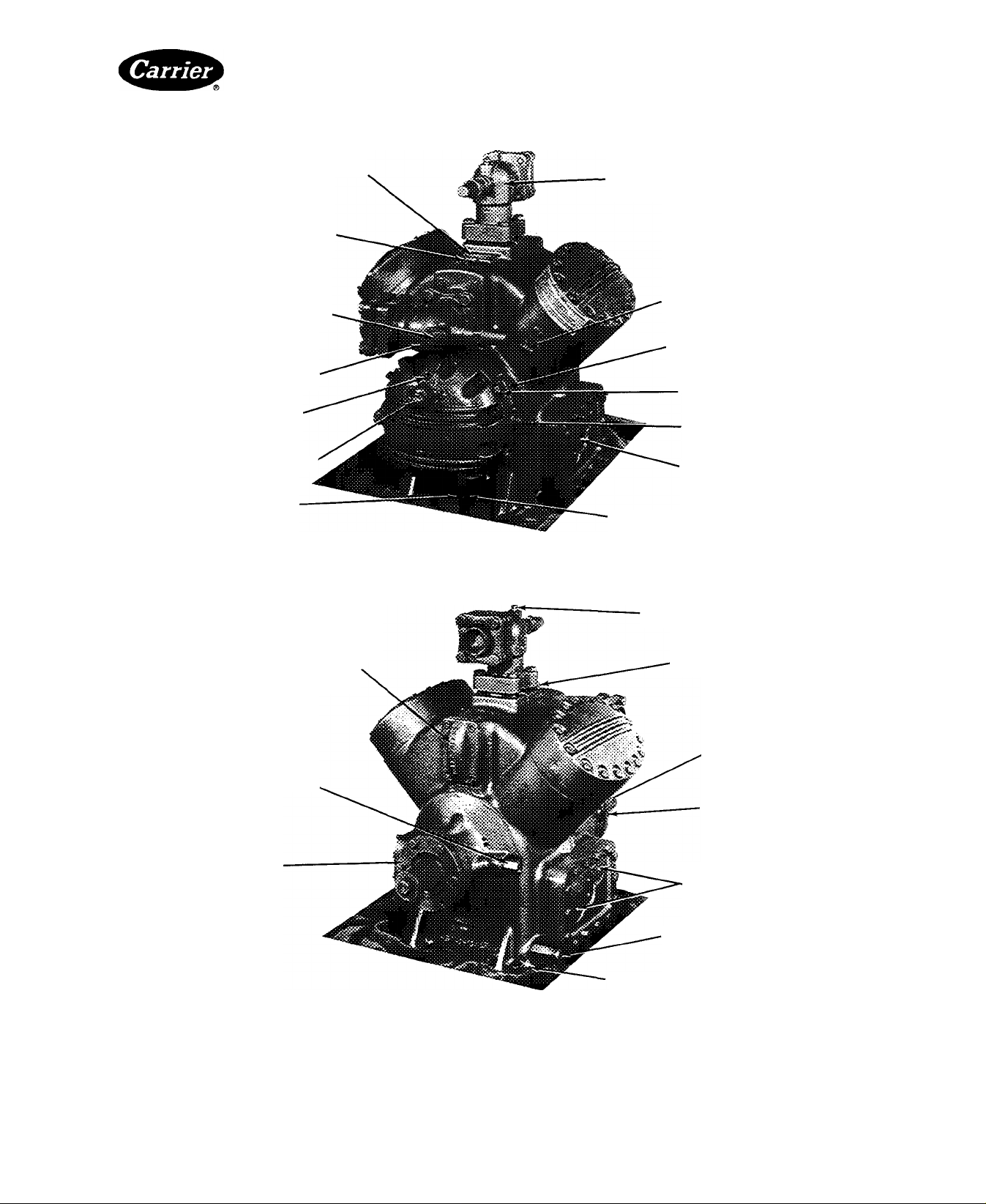
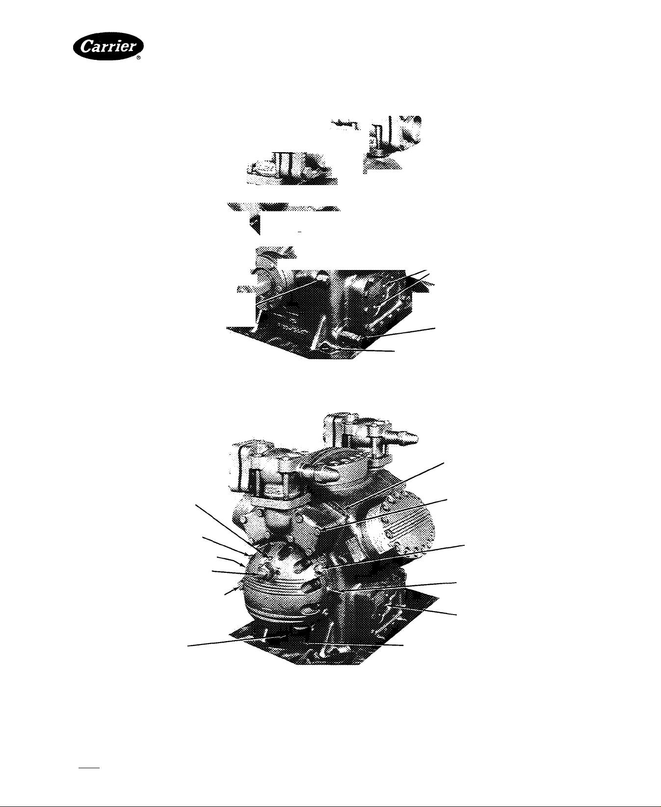
Step 2 — Receive Machine (Fig. 1 through 8)
BEFORE UNLOADING — Check unit nameplates
against model and serial numbers recorded in job speci
fications. Check all items against shipping list, and
examine items carefully for any shipping damage. If
damage is found or any major component has torn loose
from its anchorage, have transportation inspectors
examine it before unloading. File claim immediately with
shipping company for any loss or damage.
..............................
..........................
(Continued on page 10.)
______
Page
31
32
33
34
37
20 in.
30 in.
Manufacturer reserves the right to discontinue, or change at any time, specifications or designs without notice and without incurring obligations.
Book
Tab
2a
PC 111
Catalog No 530-526
Printed inUS A Form5F,H-11SI
For replacement Items use Carrier Specllled Parts
Pg 1
2-86 Replaces: 5F,FI-9SI
Page 2
5F,H
HKATtNG A COOLING
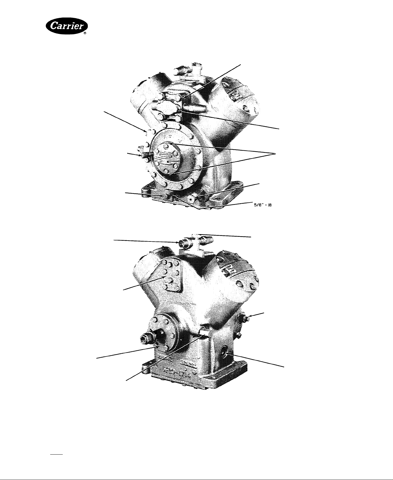
OIL FILLER PLUG
5/8"-18
OIL PRESSURE CONNECTION'
1/4" IPS
OIL DRAIN PLUG 5/8"-18
Open-Drive Compressors
SUCTION SHUTOFF VALVE
I- I /8" ODF
GAGE CONNECTION
1/4" IPS
OIL PUMP ROTATION
ARROWS
CRANKCASE HEATER CASING
(PIPE CAP 1/2" FPT)
PUMP INTAKE PLUG (MAGNETIC)
DISCHARGE SHUTOFF.
VALVE-7/8^ ODF
SUCTION AND DISCHARGE
MANIFOLD COVER-REMOVE
FOR ACCESS TO SUCTION
STRAINER
SEAL COVER
OIL PRESSURE REGULATOR
Fig. 1 — 5F20; 2-Cylinder Compressor
GAGE CONNECTION
1/4" IPS
OIL PRESSURE CONNECTION
5/8" - 18
OIL LEVEL SIGHT
GLASS
© Tab 2a
Manufacturer reserves the right to discontinue, or change at any time, specifications or designs without notice and wilhout incurring obligations.
Book 12
PC111 Catalog No 530-526 PrintedinUSA Form 5F,H-11SI Pg2 588 2-86 Replaces: 5F,H-9SI
For replacement Items use Carrier Specified Parts
Page 3
5F,H
HEATING A COOLING
DISCHARGE SHUTOFF VALVE
1-3/8" ODF
GAGE CONNECTION
1/4"-IPS
SEAL COVER
Open-Drive Compressors
OIL PRESSURE
REGULATING VALVE
OIL LEVEL SIGHT
GLASS
OIL FILLER PLUG
5/8"-18
OIL PRESSURE CONNECTION
5/8"-18
OIL PRESSURE CONNECTION
1/4" IPS
OIL DRAIN PLUG (HIDDEN)
5/8"- 18
PUMP INTAKE PLUG (MAGNETIC)
5/8 '-18
Fig. 2 — 5F30; 3-Cylinder Compressor
SUCTION SHUTOFF VALVE
1-5/8" ODF (REMOVE FOR
ACCESS TO SUCTION STRAINER)
1/4" IPS GAGE CONNECTION
OIL PUMP ROTATION ARROWS
CRANKCASE HEATER
CASING (PIPE CAP 1/2" FPT)
Manufacturer reserves the right to discontinue, or change at any time, specifications or designs without notice and without Incurring obligations.
Book|2 PC 111 Catalog No 530-526 PrintedinUSA Form5F,H-11SI Pg3 2-86 Replaces: 5F,H-9SI
Tab 2a
For replacement Items use Carrier Specitled Parts.
Page 4
5F,H
HEATING A COOLING
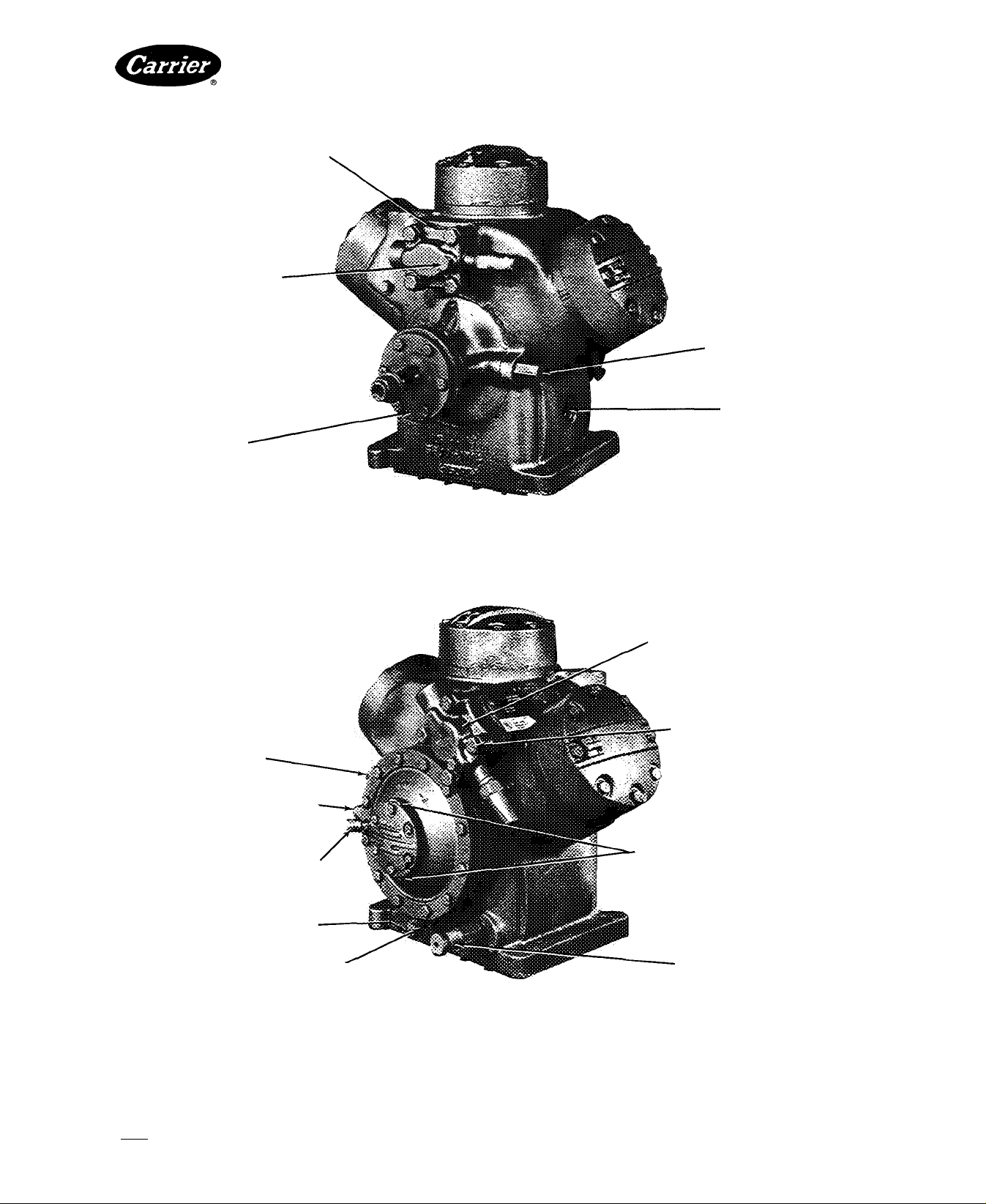
DISCHARGE SHUTOFF VALVE
1-3/8" ODF
HIGH-PRESSURE CONTROL
CONNECTION
1/4" IPS
SUCTION MANIFOLD COVER PLATE
(REMOVE FOR ACCESS TO SUCTION
STRAINER)
OIL PRESSURE REGULATOR
SEAL COVER
DOWEL HOLE
Open-Drive Compressors
1/4" IPS GAGE CONNECTION
1/4 IPS PNEUMATIC
CONTROL CONNECTION
OIL PUMP PRESSURE
3/8 IPS
OPENING TO CRANKCASE
CONTROL OIL PRESSURE
CAPACITY CONTROL VALVE
CRANKCASE HEATER CASING
(PIPE CAP 1/2" FPT)
SUCTION SHUTOFF VALVE
1-5/8" ODF
OIL FILLER PLUG
5/8"-18
OIL PRESSURE CONNECTION
1/4" IPS
DOWEL HOLE.
PUMP INTAKE PLUG (MAGNETIC)5/8"-l8
NAMEPLATE
Fig. 3 — 5F40; 4-Cylinder Compressor
1/4" IPS GAGE CONNECTION
OIL PUMP ROTATION ARROWS
OIL DRAIN PLUG 5/8 -18
LOW-PRESSURE CONTROL
CONNECTION TO DUAL
PRESSURESTAT 1/4" IPS
Manufacturer reserves the right to discontinue, or change at any time, specifications or designs without notice and without incurring obligations.
Bool<|2 PC 111 Catalog No 530-526 PrintedinUSA Form5F,H-11SI Pg4 2-86 Replaces: 5F,H-9SI
Tab 2a
For replacement items use Carrier Specified Parts.
Page 5
5F,H
HEATING A COOLING
SUCTION SHUTOFF VALVE
2-1/8" ODF
DISCHARGE SHUTOFF VALVE
1-5/8" ODF
HIGH-PRESSURE CONTROL
CONNECTION (HIDDEN)
1/4" IPS
LOW-PRESSURE CONTROL
CONNECTION
1/4" IPS
SEAL COVER
DOWEL HOLE
Open-Drive Compressors
1/4" IPS PNEUMATIC
CONTROL CONNECTION
CONTROL OIL PRESSURE
CAPACITY CONTROL VALVE
OIL PRESSURE REGULATOR
CRANKCASE HEATER CASING{PIPE CAP 1/2" FPT)
I
SUCTION MANIFOLD
(REMOVE FOR ACCESS TO
SUCTION STRAINERS)
OIL FILLER PLUG
5/8"-l8
OIL PUMP PRESSURE
CONTROL OIL STRAINER
OIL PRESSURE CONNECTION
1/4" IPS
3/8" IPS (OPENING TO CRANKCASE)
PUMP INTAKE PLUG (MAGNETIC)
5/8"-18
OIL DRAIN PLUG 5/8"-18
Fig. 4 — 5F60; 6-Cylinder Compressor
NAMEPLATE
OIL PUMP ROTATION ARROWS
PRESSURE
CONTROL SWITCH STUDS
Manufacturer reserves the right to discontinue, or change at any time, specifications or designs without notice and without incurring obligations.
Book|2 PC 111 Catalog No 530-526 Printed inUS A Form5F,H-11SI Pg5 2-86 Replaces: 5F,H-9SI
Tab |2a
For replacement items use Carrier Specified Parts.
Page 6
5F,H
HEATINQ t COOLING
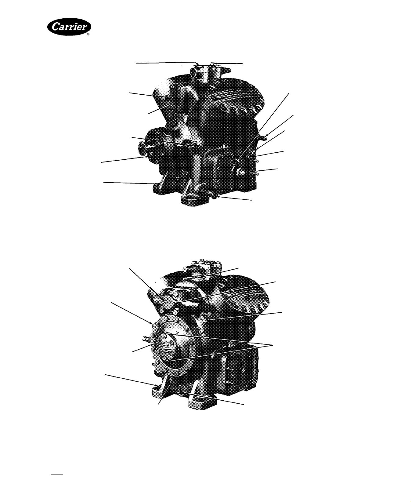
HIGH-PRESSURE CONNECTION
1/4" IPS
SUCTION GAGE CONNECTION
1/4" IPS
SUCTION SHUTOFF VALVE
2-5/8“ OOF
PNEUMATIC CONTROLCONNECTION
1/4" IPS
CAPACITY CONTROL VALVE'
DRAIN PLUG
NAMEPLATE
Open-Drive Compressors
DISCHARGE SHUTOFF VALVE
2-1/8" ODF
LOW PRESSURE CONNECTION
1/4" IPS
OIL PUMP ROTATION ARROW
OIL FILLER PLUG 5/8 -18
CONTROL OIL PRESSURE
OIL LEVEL SIGHT GLASS
CRANKCASE DRAIN
SUCTION DISCHARGE MANIFOLD COVER
(REMOVE FOR ACCESS TO SUCTION
STRAINER AND HIGH-PRESSURE
RELIEF VALVE)
OIL PRESSURE REGULATOR
SEAL COVER PLATE
Fig. 5 — 5H40, 46; 4-Cylinder Compressors
DISCHARGE GAGE CONNECTION
1/4" IPS
HIGH-PRESSURE CONTROL
CONNECTION 1/4" IPS
OPENING TO
CRANKCASE (HIDDEN)
1/4" IPS
OIL PUMP PRESSURE
PLUGGED OPENINGS
FOR INTERCONNECTION
(NOT STANDARD)
CRANKCASE HEATER CASING
(PIPE CAP 1/2" FPT)
DOWEL HOLE
Manufacturer reserves the right to discontinue, or change at any time, specifications or designs without notice and without incurring obiigations.
Book|2 PC 111 Catalog No 530-526 PrintedinUSA Form5F,H-11SI Pg6 2-86 Replaces: 5F,H-9SI
Tab |2a
For replacement Items use Carrier Specltled Parts
Page 7
5F,H
.......CO.... Open-Drive Compressors
i
^ DISCHARGE SHUTOFF " I
'PS 3-1/8 OOF
i ^ . .
'.
......................
J W-
HIGH-PRESSURE CONTROL ’’'i ;
CONNECTION 1/4" IPS--------------------------------ig ?■
SEAL COVER PLATE—^ ■- sjfe-^ , (NOT STANDARD)
OIL PRESSURE REGULATORc^SmB .CRANKCASE HEATER
EilllllllllllllllKi^ № «>.
* C ■"
-DOWEL HOLE
PLUGGED OPENINGS
^ FOR INTERCONNECTION
CASING (PIPE CAP 1/2" FPT)
#
PNEUMATIC CONTROL
CONNECTION 1/4" IPS
OPENING TO CRANKCASE
1/4" IPS
OIL PUMP PRESSURE (HIDDEN)
CAPACITY CONTROL VALVE
CONTROL OIL STRAINER PLUG
5/8"-18
PUMP INTAKE PLUG
MAGNETIC 5/8"-18
Fig. 6 — 5H60. 66; 6-Cylinder Compressors
CRANKCASE DRAIN
ACCESS TO HIGHPRESSURE RELIEF VALVE
SUCTION MANIFOLD
(REMOVE FOR ACCESS
TO SUCTION STRAINER)
OIL FILLER PLUG
5/8"-18
CONTROL OIL PRESSURE
OIL LEVEL SIGHT GLASS
Manufacturer reserves the right to discontinue, or change at any time, specifications or designs without notice and without incurring obligations.
Book I2 PC111 Catalog No 530-526 Printed in U.S A Form5F,H-11Si Pg7 588 2-86 Repiaces: 5F,H-9Si
Tab 2a
For replacement items use Carrier Specified Parts.
Page 8

5F,H
HEATING & COOLING
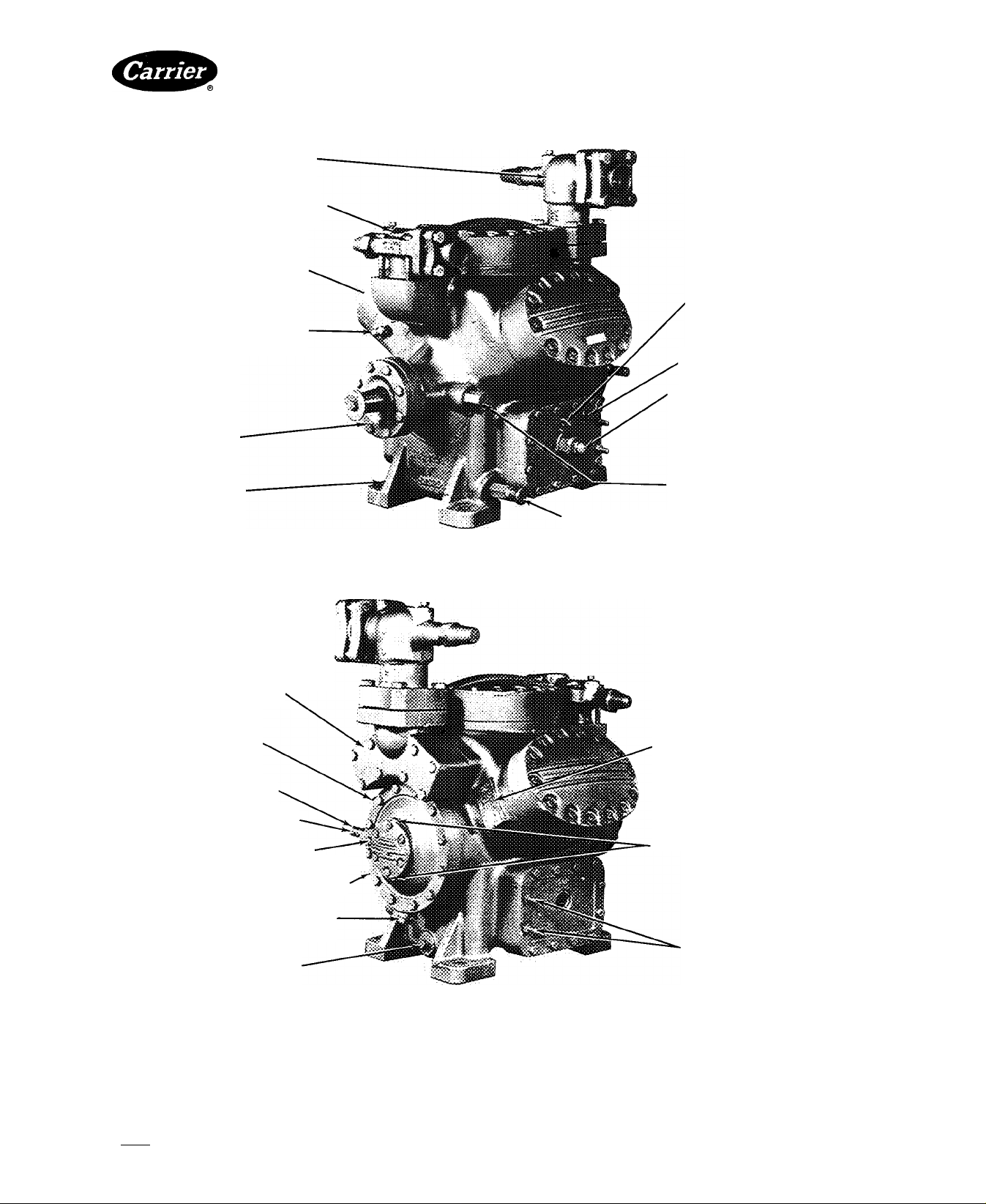
HIGH-PRESSURE RELIEF VALVE AND
MANIFOLD COVER PLATE
SEAL COVER PLATE
OIL PRESSURE REGULATOR
Open-Drive Compressors
NAMEPLATE
plugged openings
FOR interconnection
{NOT STANDARD)
CRANKCASE HEATER CASINGS
(PIPE CAP 1/2" FPT)
SUCTION SHUTOFF VALVE
3-1/8“ ODF
SUCTION MANIFOLD COVER
(REMOVE FOR ACCESS TO
SUCTION STRAINER)
PNEUMATIC CONTROL
CONNECTION 1/4" IPS
OPENING TO CRANKCASE
1/4" IPS
CAPACITY CONTROL VALVE
ADJUSTING STEM
CONTROL OIL STRAINER
PLUG 5/8"-18
OIL FILLER PLUG
CRANKCASE DRAIN
Fig. 7 — 5H80, 86; 8-Cylinder Compressors
DISCHARGE SHUTOFF VALVE
3-1/8" ODF
GAGE CONNECTIONS
1/4" IPS
HIGH-PRESSURE CONTROL
CONNECTION 1/4" IPS
LOW-PRESSURE CONTROL
CONNECTION 1/4" IPS
CENTER MAIN BEARING
RETAINING SCREW ACCESS
OIL PUMP
ROTATION ARROW (TAG)
- CONTROL OIL PRESSURE
OIL LEVEL SIGHT GLASS
Manufacturer reserves the right to discontinue, or change at any time, specifications or designs without notice and without incurring obiigations.
Book|2 PC 111 Catalog No 530-526 PrintedinUSA Form 5F,H-11SI Pg8 588 2-86 Replaces; 5F,H-9SI
Tab T2a
For replacement items use Carrier Specified Parts
Page 9

5F,H
HEATING A COOLING
DISCHARGE SERVICE-
i
VALVE 4-1/8" ODF
GAS EQUALIZER CONNECTION
OIL EQUALIZER
CONNECTION
OIL PUMP PRESSURE
(BEFORE OIL FILTER)
FULL FLOW HIGH-PRESSURE
OIL FILTER
Open-Drive Compressors
RELIEF VALVE DISCHARGE
PRESSURE
SUCTION SERVICE VALVE
4-1/8 "ODF
SUCTION MANIFOLD
COVER PLATE
(REMOVE FOR ACCESS
TO SUCTION
STRAINER)
OIL FILLER
PLUG (ALSO USED
FOR LOW-PRESSURE
OIL LINE CONNECTION)
CAPACITY CONTROL
VALVE
OIL PUMP ROTATION ARROW
ON OIL PUMP COVER
CONTROL aL PRESSURE
CONNECTION 1/4' FPT
CRANKCASE DRAIN PLUG
OIL PRESSURE GAGE SHUTOFF
VALVE (AFTER OIL FILTER)
DISCHARGE GAGE
CONNECTION 1/4" IPS
OIL PRESSURE REGULATOR
CENTER MAIN BEARING
RETAINING SCREW ACCESS
(HIDDEN)
SEAL COVER PLATE
SUCTION MANIFOLD OIL
PASSAGES
Fig. 8 — 5H120, 126; 12-Cylinder Compressors
SUCTION GAGE CONNECTION
1/4" IPS
LEVEL SIGHT GLASS
(ON OPPOSITE SIDE OF COMPRESSOR)
HIGH-PRESSURE OIL CONNECTION
1/4“ IPS
#
Manufacturer reserves the right to discontinue, or change at any time, specifications or designs without notice and without incurring obligations.
Book [2 PC 111 Catalog No 530-526 Printed inUS A Form5F,H-11SI Pg9 2-86 Replaces: 5F,H-9SI
Tab 12a For replacement items use Carrier Specified Parts.
Page 10
5F,H
HEATING A COOLING
RIG UNIT CAREFULLY — Check that rigging equip
ment can safely handle the approximate equipment
weights for compressors and condensing units.
Rig and move unit earefully to prevent damage to
mounting brackets, refrigerant piping or connections.
Step 3 — Install Unit
TO MOUNT MOTOR ON BASE -- The motor fasten
ing set supplied with all compressor units (except 5F20,
30, and all OEM models) includes motor blocks and
shims for motor alignment; cap screws, plate washers
and lock washers for fastening motor to base; taper dowel
pins for securing motor position after alignment; and
beveled washers for fastening the unit base to accessory
vibration isolators.
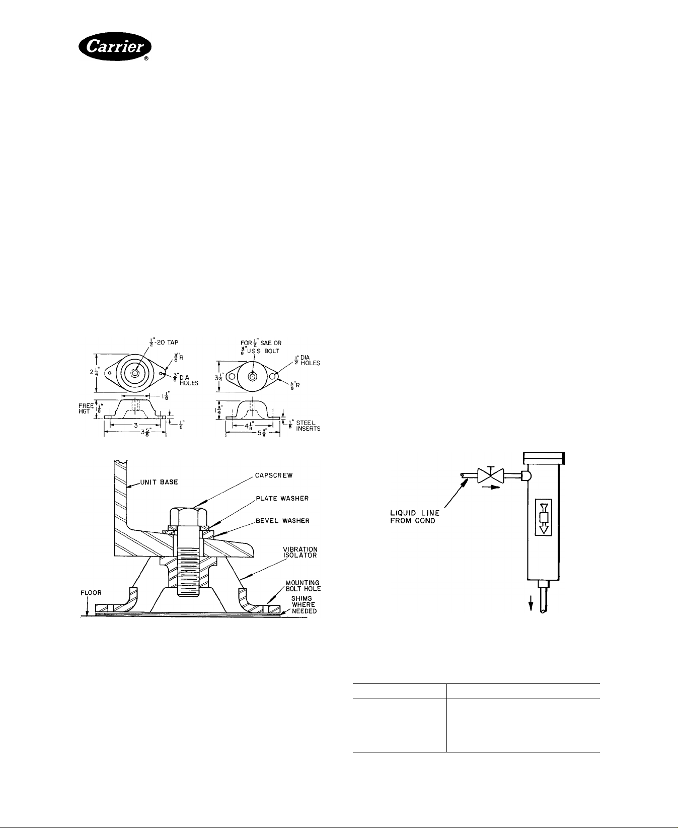
If vibration isolators are used, attach to base (Fig. 9)
To avoid damaging the isolators, lift unit from ends when
attaching isolators.
With compressor and motor positioned on the base,
check the height of the vibration isolators. Shim between
isolators and floor as required to level compressor base.
When level, secure vibration isolators to floor. Check that
beveled washer (Fig. 9) is in place.
Open-Drive Compressors
Remove soldered shipping cap from hot gas inlet. To
prevent solder from dripping into inlet pipe while un
soldering, rotate condenser until pipe is below horizontal
position. Return inlet to upright vertical position.
Tighten lower support straps enough to lift condenser
off stands. Place upper straps loosely in position with a
strip of protective material between condenser and strap
(5F20 and 5F30 units use lower strap only).
TO MOUNT COMPRESSOR BASE ON SUPPORT
STANDS — Place compressor base on support stands
with 2 extra strips of protective material between top of
condenser and base. Bolt base into position with cap
screws and lock washers provided.
Step 4 — Assemble Refrigerant Piping and Com
ponents — Refrigerant connection sizes are given in
Table 4.
COMPRESSOR DISCHARGE PIPING — Refer to
Condensing Unit Piping Installation Instructions for
information.
REFRIGERANT DRIER — A replaceable-core filter
drier is recommended for most systems, and is essential
on all low-temperature systems. Mount the field-supplied
filter drier in the liquid line. Include a shutoff valve to
permit isolation of drier for servicing (Fig. 10).
Install a moisture indicator on downstream side of
drier to indicate when drier cartridges need replacing.
FELT FILTERS — Install felt filter supplied with com
pressor in suction strainer (Fig. 1 through 5). Remove
filter after 50 hours of operation. If clean, discard it; if
dirty, clean with kerosene or neutral spirits and insert for
another 50 hours of operation.
filter was cleaned and reinstalled. Figure 10 and Table 1
give information on replacement filter packages.
Tag unit to show date that
Fig.
Fig. 9 — Typical Vibration Isolator Mounting
TO MOUNT CARRIER COMPRESSOR UNITS AND
CONDENSER PACKAGES — Bolt the compressor’s
lower support straps loosely to underside of each support
stand and place strips of protective material, such as
COMPRESSOR
Fabrica, on straps. Position condenser on stands with hot
gas inlet at top of condenser and liquid shutoff valve
connection facing compressor end of base. Check that
condenser overhangs support stands for same distance
on each end.
Manufacturer reserves the right to discontinue, or change at any time, specifications or designs without notice and without incurring obligations.
Book|2 PC111 Catalog No 530-526 PrintedinUSA Form5F,H-11SI PglO 2-86 Replaces: 5F,H-9SI
Tab 2a
For replacement Items use Carrier Specified Parts.
10 — Refrigerant Filter Drier and
Shutoff Valve Arrangement
Table 1 — Suction (Felt) Filter Packages
FILTER PACKAGE PART NO.
5F40
5F60
5H40,46
5H60,66
5H80,86
5H120,126
5F40-A352
5F60-A352
5H40-A382
5H60-A382
5H80-A382
5H120-A382
Page 11
5F,H
HEATING A COOLING
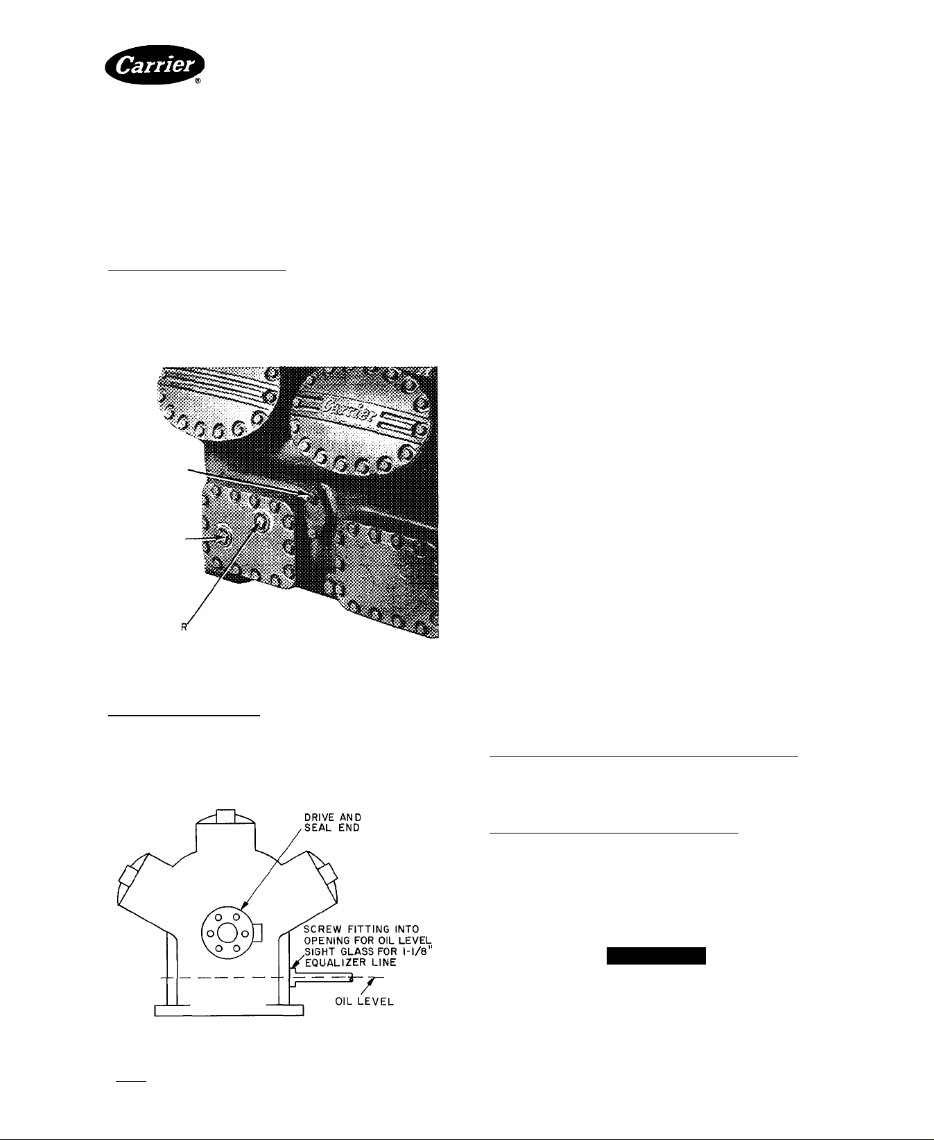
Step 5 — Install Multiple Compressors
EQUALIZING LINES — Compressors operating in
parallel require interconnecting lines for oil and gas
pressure equalization. Special handhole cover plates,
equipped with tapped holes for equalizing lines, are avail
able as options for sizes 5F40 and 5F60, as well as for
sizes 5H40, 46, 60, 66, 80, and 86 eompressors (Fig. 11).
An oil float system is an acceptable alternative to
equalizer lines.
5H120 and 126 Compressors include factory-supplied,
tapped cover plate. On these compressors, use only
lower connection for oil equalization (Fig. 11). Connect
gas equalizing line to flange connection shown. Mat
ing flange for 1-1/8 in. line is Carrier Part No.
DK24CA712 (Mueller Part No. A-5151); gasket Part No.
is DK29GA005 (Mueller Part No. A-5152).
GAS EQUALIZER
CONNECTION
i4"od flange
(5HI20-I26 ONLY!
Open-Drive Compressors
Step 6 — Make Electrical Connections
GENERAL NOTES
1. Factory wiring complies with National Electrical Code
(NEC). Any field modifications or additions must
comply with all applicable codes.
2. *For control circuit information, refer to Accessory
Control Panel Installation Instructions.
3. If control circuit power is supplied from a separate
source, rather than from a transformer, bring 115-v
power through a field-supplied, 15-amp disconnect,
in compliance with NEC Section 440-14 (disconnect
must be in sight from and readily accessible from
unit).
4. Open control-power disconnect only when servicing
unit. Crankcase heaters must remain energized
when unit is not operating.
5. *Factory wiring is for single pumpout control. Do not
use pumpout control on equipment used with DX
coolers. Wiring label shows field connections used
with DX cooler.
6. *Contactor C2 is used with 208-v motors, 25 through
60 hp, and 460-v motors, 50 through 150 hp.
7. *When field interlocks are used, remove jumpers
between terminals 3 and 4, and between terminals
7 and 8 on TB2.
♦Refers to compressor units and condensing units only.
OIL EQUALIZER
connection
l" IPS
GAS EQUALIZE
connection
Fig. 11 — Special Handhole Cover and
Equalizer Connections (Typical)
5F20 and 30 Compressors have no special tapped cover
plate. Use opening for oil sight glass to attach the I -1 / 8 in.
line for gas and oil equalization (Fig. 12). Accessory
Package No. 06DA900072 provides two I/8-in. line
adapters to thread into the sight glass opening. If addi
tional equalization is desired, run a 3/8-in. line to the oilfilter plug connection (Fig. I and 2).
ATTACH POWER WIRES TO COMPRESSOR
MOTOR — Attach power wires in accordance with
motor manufacturer’s instructions and in compliance
with NEC and applicable local codes.
CHECK MOTOR ROTATION — Before connecting
motor to compressor, check direction of motor rotation.
Rotation must be in same direction as that indicated by
arrow on compressor pump cover (or on plate attached
near pump-end bearing housing). If direction is not the
same, reverse motor rotation by reversing any 2 power
leads to motor.
If rotation of oil pump is reversed, reverse direction of
pump rotation arrow as well. At that time make the
following adjustments:
All 5F Compressors and 5H120and 126 Compressors —
Remove 6 cap screws from oil pump cover (Fig. 1-4, 8).
Do not damage gasket. Rotate cover 180 degrees and
replace. Arrow at top of oil cover will indicate new direc
tion of rotation.
5F40, 46, 60. 66. 80 and 86 Compressors — Drain oil
below level of pump-end dome cover (Fig. 5-7). Remove
pump-end cover to expose oil pump cover in center of
main bearing housing. Rotate oil pump cover 180 degrees
and replace it. Replace pump-end cover and reverse
external arrow to match new direction of rotation. Proper
direction can later be checked without removing pumpend cover.
#
A CAUTION
If the special gasket between oil pump cover and
oil pump is damaged, replace with correct gasket
only. Check oil pressure immediately after starting
Fig. 12 — Equalizer Connections (5F20 and 5F30)
Manufacturer reserves the right to discontinue, or change at any time, specifications or designs without notice and without incurring obiigations.
BookI 2 PC 111 Catalog No 530-526 PrintedinUSA Form5F,H-11SI Pgll 2-86 Replaces: 5F.H-9SI
For replacement items use Carrier Specitled PartsTab 2a
compressor.
Page 12
5F,H
HEATING A COOLING
INSTALL CRANKCASE HEATER — Wire heater to
relay or set of normally closed auxiliary contacts on
compressor starter to de-energize it when compressor
is operating.
Remove rubber plug from crankcase heater casing
(Fig. 1-8), and insert heater element entirely into casing.
Element should fit snugly, not loosely. Wire to comply
with applicable electrical codes.
When crankcase heater is installed, system can be
operated on single pumpout cycle, unless used with a DX
cooler.
Table 2 lists crankcase heater packages. Table 3 shows
corresponding relays. Use of 2 heaters on a 5H80 or
5H120 compressor requires only one relay.
Control circuit voltage determines relay coil voltage.
This voltage must be specified when ordering relays.
See Accessory Compressor Crankcase Heater Instal
lation Instructions for additional information.
Table 4 — Physical Data
COMPRESSOR UNIT AND
CONDENSING UNIT
REFRIGERANT
COMPRESSOR DATA
Maximum Rpm
Minimum Rpm
Minimum Rpm Capacity
Control
Number of Cylinders
Bore (in.)
Stroke (In.)
Compressor Connections
(in. O.D.)
Suction
Discharge
Oil Charge* (pt) (See Notes)
Normal Oil Pressure*
Oil Flow Rate (gpm)
Oil Safety Switch
Cut-in (psig) (See Notes
Cutout (psig) 3 and 4)
High-Pressure Switchf
Cutout Range
Differential (psi)
Factory Setting (psig)
Low-Pressure Switchf
Cutout Range
Differential (psi)
Factory Setting (psig)
Low Side Maximum Pressure
CONDENSER DATA
Maximum Refrigerant Storage
Capacity** (lb)
Minimum Refrigerant Operating
Charge (ib)
Maximum Operating Pressure
Refrigerant Side
Water Side
__________
___________
R-12
R-22
R-502
R-12
R-22
R-502
5F20 5F30
600
2
2'/2
2
VA
Ve
5F40 5F60 5H40 5H46 5H60 5H66 5H80 5H86 5H120
700 800
3
2'/2
2
IVs
1%
4
2'/2
2
V/e
1%
55 12 13 18 18 21 21 41
1 5_____________I_____________________
5F20f 5F30f 5F40
40 4 50 7 79.4
37 2
38.2
1 8 27
1.9 2.9
20
46.4 72 8
47.9 75.0
30 140
127 14.5 33.0
13.1 15.0 34.4 38.2
150 psig
900 800 800 900 900 1100
6
2'/2
2
2Ve
VA
Open-Drive Compressors
Table 2 — 5F,H Compressor Crankcase
COMPRESSOR
5F20,30,40,60
5H40,46,60,66
5H80,86,120,126
Table 3 — Crankcase Heater Relay (60 Hz)
CONTROL CIRCUIT VOLTAGE
208/230
R-12, R-22, R-502
400 (required for proper lubrication)
4
3Va
2%
2%
2'A
45-55 psig above suction pressure —
150-395 (adjustable) nominal
Cutout, 300 ± 15, Cut-in, 210 ± 10
20 in Hg vac to 60 psig (adjustable)
Cutout, 50 ± 4; Cut-in, 120 ± 6
5F60
09RH-
89 6 154 212
82 0 139 193
84.6 145 199
027
160 37.0 41 0 51 0
1750
4
3’/4
3%
2%
2'A
6
3%
2%
3'A
3'A
3_0
15 - 19.5
11 - 15
60-150 (adjustable)
60-90 (adjustable)
245 psig
09RH-
043
37 0 46.0 46 0 71
09RH-
054
263
239
248 223 265 337
47.3 47.3 73 94
385 psig
Heater Package
ELECTRICAL
CHARACTERISTICS
Volts Watts
115
230
115
230
115
230
115
6
3'/4
3y,6
3'A
3'A
___________
8
3'/4
2%
3'A
3'A
09RH-
070
238 282 358 475
216
51 0 78
250 psig
PACKAGE NO.
100
100
200
200
200
200
-5-F-20—381
-5-F-20—391
-5-H-40—381
-5-H-40—391
-5-J-40—281
-5-J-40—291
PART NO.
HN61AJ-101
HN61AJ-108
1100 900 900
8
3'/4
3V,6
3'A
3'A
41
12
3'/4
2%
4'/e
4'A
61 61
4.5
09RH-
257
084
09RH-
097
327 432
100 126
91 114
12
3'/4
3V,6
4'A
4'A
09RH-
127
447
118
‘Nominal oil pressures shown in Physical Data table are above suction
pressure, i e , pressure differential between suction pressure and dis
charge pressure of oil pump
tSee Table 5 for typical pressure switch settings
fShell-and-coil condensers All other 5F,H condensers are shell-and-
tube
‘‘Condenser storage capacity 80% filled with liquid refrigerant at 90 F
NOTES:
1 Oil flow rate is the nominal oil pump capacity
2 The following oil (or equivalents) are specified for use in 5F,H
compressors
5F20 and 30: Witco Chemical Co — Suniso 4GS
5F40-5H126: Witco Chemical Co. — Suniso 3GS
3 Differential switch (oil safety switch) has time delay of 30 to 60 seconds
4 Oil safety switch has manual reset
Texaco, Inc — WF32
Shrieve Chemical Co — Zerol 150 (synthetic)
Manufacturer reserves the right to discontinue, or change at any time, specifications or designs without notice and without incurring obligations.
Book 12 PC 111 Catalog No 530-526 Printed inUS A Form5F,H-11SI Pg12 2-86 Replaces: 5F,H-9SI
Tab 12a
For replacement items use Carrier Specified Parts.
Page 13

5F,H
HEATING A COOLING
Step 7 — Check Compressor/Motor Alignment
BELT DRIVE — See Accessory Belt Drive Package
manual for installation and alignment instructions.
DIRECT DRIVE — Install and align compressor,
coupling and motor as described in manual for Flexible
Couplings for Direct-Drive Units.
HOT CHECK AND DOWELING — To help maintain
alignment, and to ensure exact repositioning of the
motor after servicing, the motor and eompressor must
be doweled to tbe base. Install doweling only after
motor!eompressor alignment has been hot checked
(checked after the compressor has warmed up to oper
ating temperature after initial alignment).
After hot check and while components are still at
Open-Drive Compressors
PREPARE FOR INITIAL START-UP
Evacuate, Dehydrate and Leak Test the entire
refrigerant system as described in Carrier Standard
Service Techniques Manual, Chapter 1, Sections 1-6
and 1-7.
LEAK TESTING
Preferred Method — Charge the system to 10 psig with
refrigerant. Add dry nitrogen or dry air (DO NOT USE
OXYGEN) until system pressure is 150 psig. Check for
leaks with a halide or electronic leak detector.
Alternate Method — Charge the system with dry
nitrogen or dry air (DO NOT USE OXYGEN) to 40 psig
and use soap-bubble test to find large leaks.
operating temperature, drill and ream 2 holes through
diagonally-opposite motor and compressor feet and the
base. Use a 9/32-in. drill and a no. 6 taper reamer. Secure
the motor and compressor to the base with the no. 6 x
2-1/2 in. taper dowel pins provided in the motor fasten
Do not use compressor to build up pressure. Do not
overcharge the system.
A CAUTION
ing set.
Coat the dowels with white lead or other lubricant to
prevent rusting, and tap the dowel lightly into position
so that 1/16 of taper is left above the motor foot.
Check that all dowels are tight and that they do not
bottom.
Step 8 — Assemble Water Piping — See WaterCooled Condensers Installation Instructions and WaterCooled Heads Installation Instructions for information.
Step 9 — Prepare Lubrication System
m
INSTALL OPTIONAL EQUIPMENT — Consult local
Carrier representative for information on these
accessories.
Refrigerant Charging — Use the sight glass method
to charge the system. See Section 1-8 of Carrier Standard
Service Techniques Manual, Chapter 1, for details.
Charge the system to a clear sight glass while holding
saturated condensing pressure constant at 125 F for air
cooled systems or 105 F for water-cooled systems. Add
additional refrigerant to fill condenser subcooler
coils, if required.
5F,H CONDENSING UNITS ^ After a clear sight glass
is obtained, add charge until liquid refrigerant reaches
the condenser liquid level test cock.
5F,H COMPRESSOR UNITS — See condenser data for
additional charge requirements.
Oil Filter — Oil filter for 5H40 through 5H86 com
pressors is available as separate accessory package. Refer
to Accessory Oil Filter Package Installation Instructions
for installation procedures.
If an accessory oil cooler is also installed (see below),
pipe oil filter into system as shown on diagrams in Acces
sory Oil Cooler Installation Instructions.
Oil Cooler — Refer to Accessory Oil Cooler Installation
Instructions included with this accessory package.
Readjust oil-cooler water flow so that it maintains
specified oil temperature when compressor has reached
operating temperature.
Oil Separator — If oil separator is used in system piping,
pipe oil return line to compressor suction line. To mini
mize possibility of flooding compressor with oil, oil
return line diameter should not exceed 1/4 inch. In addi
tion, line should have manual shutoff valve to throttle
oil flow as required and to isolate separator for service.
CHECK OIL LEVEL — Check that oil level is visible
at center of compressor sight glass. Compressors that use
optional equipment such as filter, cooler, and oil
separator described above will require a greater oil
charge than listed in Table 4. Recheck oil level after
operating compressor. If unit needs additional oil, use
only dehydrated, wax-free, refrigeration-grade oil of
suitable viseosity. Table 4 lists oil suitable for use in
m
reciprocating compressors.
Preliminary Steps
1. Energize crankcase heater for at least 24 hours before
starting unit.
2. If control transformer is not used, operate electrical
control circuit with main power switch OFF to ensure
that field connections have been properly made.
3. Install felt sock filter for the first 50 hours of com
pressor operation. Remove and inspect the filter,
clean it if required and replace it for another 50 hours.
Remove sock when system is clean. (Not applicable for
5F20 and 5F30 units.)
4. Cheek that motor rotates in direction that the arrow
on the eompressor oil pump cover indicates. Refer to
Installation, Step 5, under Check Motor Rotation.
5. Check that oil fills 1/3 to 1/2 of the compressor
sight glass.
6. Open water supply valve to condenser. Open pressure
line valve of water-regulating valve (if used). If
eompressor unit is equipped with air-cooled con
denser, turn on condenser fan.
7. Backseat (open) compressor suction and discharge
service valves. Open liquid line valve at receiver.
8. Start evaporator fan or chilled water pump.
START-UP
Manufacturer reserves the right to discontinue, or change at any time, specifications or designs without notice and without incurring obligations.
Book 2
Tab
2a
PC111
Catalog No 530-526 PrintedinUSA Form5F,H-11SI Pgi3
For replacement Items use Carrier Specified Parts
2-86
Replaces: 5F,Fi-9SI
Page 14

5F,H
HEATING A COOLING
Start Compressor — Close main power switch
supplying current to the compressor motor.
Immediately recheck oil level and check oil pressure.
Pressure should exceed suction pressure by 45-55 psi.
If correct pressure is not reached in 10-12 seconds, stop
compressor immediately and check oil pump.
A CAUTION
If any safety device shuts down the compressor, do
not reset the control more than once before deter
mining cause of shutdown.
Check Control Operation — Refer to Carrier
Standard Service Techniques Manual, Chapter 2, for
complete instructions on checking electrical components.
HIGH- AND LOW-PRESSURE SWITCHES — A115F
and 5H units except 5F20 and 30 have factory-installed,
automatic reset, high- and low-pressure switches. (These
switches are available as accessories for 5F20 and 30
units.) Figure 13 illustrates adjustment procedures for
both switches.
Check High-Pressure Switch — Throttle the con
denser water on water-cooled unit or block the airflow
on air-cooled unit, allowing head pressure to rise grad
ually. Compressor should shut off within 15 psi of cutout
value listed in Table 4. Now reverse procedure; com
pressor should start within 10 psi of cut-in value given.
Check Low-Pressure Switch — Slowly close the
suction service valve; suction pressure will decrease.
Compressor should shut off within 4 psi of cutout value
listed in Table 5. Reverse procedure; compressor should
start within 6 psi of cut-in value given.
Open-Drive Compressors
ROBERTSHAW
A-RANGE ADJUSTMENT SCREW
TOP
B-DIFFERENTIAL ADJ SCREW
RANCO
A-RANGE ADJUSTMENT SCREW
TOP
0'^B-
DIFFERENTIAL ADJ SCREW
Table 5 — Typical Pressure Switch Settings
PRESSURESTAT
REFRIG
ERANT
CONDENSER
Water-Cooled 175 95 16 76
Air-Cooled
Water-Cooled
Air-Cooled 325
Water-Cooled 280 200 45
Air-Cooled 325
Hi!
(ps
Cutout Cut-in Cutout Cut-in
g)
225 145 16 76
280 200 36
245 36
245 45
Low
(psig)
96
96
105
105
OIL PRESSURE SAFETY SWITCH — To check, move
contact arm at left side of switch forward (Fig. 14).
Compressor should stop in approximately 45 seconds.
If compressor continues to run, check the wiring to
safety switch. If wiring is correct, switch is faulty and
should be replaced.
After completing test, wait 3 minutes; then press
restart button on front of safety switch and restart
compressor.
Check oil level in compressor sight glass after 15-20
minutes of operation. If the oil level is low, add oil by the
methods described in Carrier Standard Service Tech
niques Manual, Chapter 1, Section 1-11.
If an accessory oil cooler is provided, adjust the
water flow as required to maintain a lOOF to 120F
crankcase return oil temperature.
Screw A raises or lowers both cutout and cut-in points by a like
amount.
Range and Differential scales are on the front of the switch.
High Pressure Set cutout point first, with screw A; then set
Low Pressure: Set cut-in point first, with screw A, then set
cut-in point with screw B
cutout point with screw B
LOCATION AND ADJUSTMENTS
Fig. 13 — High- and Low-Pressure Switches
For additional information, see Oil Safety Switeh
Accessory Package Installation Instructions.
Adjust Capacity Control (if required) — See
Fig. 17 for unloading sequence.
5F20 AND 5F30 COMPRESSORS ^ Referto Capacity
Control Valve Installation Instructions for additional
information.
5F40 THROUGH 5H126 COMPRESSORS — Deter
mine the refrigerant usage:
If the system is to use R-I2, replace the 11-lb range
adjustment spring (Fig. 15) with the 7-lb spring .supplied
with compressor. A change in 1982 reversed which range
adjusting spring a customer received. The R-22/R-502
spring is now standard with the compressor. See instruc
tion tag for spring replacement procedure.
Manufacturer reserves the right to discontinue, or change at any time, specifications or designs without notice and without Incurring obligations.
Book! 2 PC111 Catalog No 530-526 PrIntedInUSA Form5F,H-11SI Pg14 2-86 Replaces: 5F,H-9SI
Tab 2a
For replacement items use Carrier Specified Parts.
Page 15

5F,H
HEATING A COOLING
CONTACT ARM
HIGH-PRESSURE
CONNECTION TO
OIL PUMP
DISCHARGE
Fig. 14 — Oil Pressure Safety Switch
RESISTANCE
CONNECT IN
SERIES WITH
CONTROL CIRCUIT
REFER TO UNIT LABEL
WIRING DIAGRAM)
LOW-PRESSURE
CONNECTION
TO CRANKCASE
T
240
VAC
±
VAC
Open-Drive Compressors
An external adjusting stem (Fig. 15) sets the control
point (suction pressure at which first step of cylinder
unloading occurs). The control point is adjustable
as follows:
R-22 and R-502 .............................................. 0 to 85psig
R-12................................................................. 0to50psig
One full clockwise turn of adjusting stem will raise the
control point approximately 6psig with R-12, or lOpsig
with R-22 and R-502.
Control oil pressure is an indication of cylinder loading
condition (Table 6). Refer to Fig. 3-8 for location of
control oil-pressure gage connection. See Accessory
Unloader Paekage Installation Instructions for addi
tional information.
Table 6 — Control Oil Pressures for
Cylinder Loading and Unloading
APPROXIMATE
COMPRESSOR STEP*
5F20 1 19 8
5F30
5F40,60; 1 30.0
5H40,46, 2
60,66,80, 3
86,120,126
1
2
4 20 0
CONTROL OIL PRESS. (psIg)
Loading Unloading
13.0
30 0
198
26.0 160
23 0
20 2
130
19.0
120
9.0
SPRING DETAILS
7-LB SPRING
R-12 USAGE
11-LB SPRING
R-22, R-502
USAGE
‘Capacity control reduction steps
To Adjust Control Point
1. Impose an artificial load on the compressor until
suction pressure exceeds control point.
2. Slowly close suction valve to lower compressor
suction pressure to eontrol point pressure.
3. When at control point pressure, turn external
adjusting stem clockwise until first step of unloading
takes place, as indicated by ehanges in control
oil pressure, current draw and sound of compressor.
Control point is now set. Reopen suction service valve.
Compressor will be fully loaded when suction pressure is
3psig (4psig with R-22 and R-502) above control point,
and will be fully unloaded when suction pressure is 4psig
(7 psig with R-22 and R-502) below control point.
5F20 AND 5F30 COMPRESSORS — Two capacity
control packages are available as accessories. One is
suitable for R-12 applications; the other for R-22 and
R-502 applications.
The adjusting stem (Fig. 15) is shipped in a backseated
(fully eounterclockwise) position. Compressor will be
fully loaded under all conditions. Adjust the capacity
control set point by the same 3-step procedure described
above for 5F40 through 5H126 compressors.
*When compressor Is received, the capacity control adjusting
stem will be backseated. (Compressor will be fully loaded under
all conditions )
m
Manufacturer reserves the right to discontinue, or change at any time, specifications or designs without notice and without incurring obligations.
Bookl 2 PC111 Catalog No 530-526 PrintedinUSA Form 5F,H-11SI Pg15 2-86 Replaces: 5F.H-9SI
Tab I 2a For replacement items use Carrier Specified Parts
Fig. 15 — Capacity Control Valve
Page 16

5F,H
HEATING A COOLING
Open-Drive Compressors
CONTROL OIL
PRESSURE
CRANKCASE
PRESSURE
5F20
Fig. 16 — 5F,H Capacity Control System (Except 5H120)
d
5F30
5H60.66
OIL PUMP
PRESSURE
B
Fig. 17 — Cylinder Unloading Sequence
Manufacturer reserves the right to discontinue, or change at any lime, specifications or designs without notice and without incurring obiigatlons.
BookI 2 PC111 Catalog No 530-526 PrintedinUSA Form5F,H-11SI Pg16 2-86 Replaces; 5F,H-9SI
Tab 2a
For replacement Items use Carrier Specified Parts.
Page 17

5F,H
HEATING «COOLING
SUCTION SHUTOFF VALVE
3-1/8“ ODF
SUCTION MANIFOLD COVER
(REMOVE FOR ACCESS TO
SUCTION STRAINER)
PNEUMATIC CONTROL
CONNECTION 1/4“ IPS
OPENING TO CRANKCASE
1/4" IPS
CAPACITY CONTROL VALVE
ADJUSTING STEM
CONTROL OIL STRAINER
PLUG 5/8“-18
OIL FILLER PLUG
CRANKCASE DRAIN
Open-Drive Compressors
DISCHARGE SHUTOFF VALVE
3-1/8“ ODF
GAGE CONNECTIONS
1/4“ IPS
HIGH-PRESSURE CONTROL
CONNECTION 1/4" IPS
LOW-PRESSURE CONTROL
CONNECTION 1/4“ IPS
CENTER MAIN BEARING
RETAINING SCREW ACCESS
OIL PUMP
ROTATION ARROW (TAG)
CONTROL OIL PRESSURE
OIL LEVEL SIGHT GLASS
Fig. 18 — 5H80, 86 8- Cylinder Compressor
m
SCHEDULED MAINTENANCE
for 5H40 through 5H86 eompressors (Fig. 19). Replace
oil filter after the first 50 hours of operation, or whenever
5F,H compressor and condensing units provide long
life and dependable service when properly operated and
regularly maintained. Establish a maintenance schedule
based on factors such as operating hours, load eonditions
and water quality. Maintenance schedules listed in this
section are offered as guides. Modify them as needed to
satisfy individual machine requirements.
Check Lubrication System — Always check com
pressor oil level before starting unit. If oil is required,
record date and amount added. Refer to Fig. 1-8 for loca
tion of oil filter plug. Table 4 shows specified types and
quantities of oil.
Use of accessory oil separator requires additional oil.
Oil level and separator float valve movement during
initial compressor operation should agree with instruc
tions furnished with the oil separator.
the oil is changed or becomes dirty.
Check yearly for clogged filter, indicated by a greater
than normal difference between oil pressure ahead of
fdter and after filter. When this difference exceeds 5 psig,
change filter as follows;
1. Close oil-line shutoff valves on each side of filter
(Fig. 19).
2. Disconnect oil lines at filter connections.
3. Loosen filter bracket; remove and replace filter body.
Refer to Accessory Oil Filter Instructions for
additional information.
The full-flow oil filter on 5H120 and 5H126 com
pressors contains a replaceable cartridge. Replaee the
filter cartridge after the first 100 hours of compressor
operation. After the initial filter change, check yearly for
filter clogging. If the pressure difference across the filter
exceeds 5 psig, pump down the compressor and then
OIL FILTER MAINTENANCE — A bleed-type, highpressure, disposable filter is available as an accessory
remove the cartridge. Figure 20 illustrates complete
filter assembly.
Manufacturer reserves the right to discontinue, or change at any time, specifications or designs without notice and without incurring obligations.
Book|2 PC111 Catalog No 530-526 PrintedinUSA Form5F,H-11SI Pg17 588 2-86 Replaces: 5F.H-9SI
Tab 2a
For replacement items use Carrier Specified Parts
Page 18

5F,H
HEATING A COOLING
SHUTOFF VALVES
PLAIN ELBOW (PART
NO DDI0CA052)
OIL FILTER'
HOUSING
-ORIFICE ELBOW (PART NO
DD40CA05I)
Fig. 19 — Oil Filter Accessory Package
(5H40 through 5H86)
CHECK OIL AND SHAFT SEAL TEMPERATURE
— The normal operating temperature of the oil in the
crankcase ranges from 100 F to 135 F when fully loaded.
Do not permit maximum oil temperature to exceed 150 F.
Conditions under which such excessive temperatures
could occur include situations where the compressor
Open-Drive Compressors
operates in a fully unloaded condition for an extended
period, because the compressor would not be able to
remove all of the heat generated by compression and
friction. In such situations, use an oil cooler to maintain
safe operating temperatures. Refer to 5F,H Application
Data for more information.
When crankcase oil temperature falls within the 120
to 135 F range, the shaft seal housing temperature should
be approximately 140 to 150 F. Shaft seal housing tem
peratures above 170 F may cause shaft seal to age rapidly,
and harden and crack. Therefore:
If shaft seal housing temperature exceeds 170 F,
STOP THE COMPRESSOR. DO NOT restart until
the cause of overheating has been identified, and
the condition corrected.
OIL COOLER USAGE — The accessory oil cooler
maintains safe operating oil temperatures when:
1. The suction gas becomes highly superheated (Table 7).
2. a. The compression ratio exceeds 5:1 on R-22
systems,
b. Application data indicates the need for an oil cooler
for R-12 and R-502 systems. This is especially
likely in increased displacement compressors such
as the 5H46, 66, 86 and 126. The compression ratio
can be determined from the following formula:
Compression _ Absolute Discharge Pressure
Ratio Absolute Suction Pressure
t
OIL PRESS 6AGE CONN
(BEFORE FILTER )
OIL FILTER HOUSING
OIL FILTER
COVER
PUMP END BEARING HEAD
OIL FILL PLUG
CAPACITY CONTROL VALVE ADJUSTING STEM
BUSHING LOC
CONTROL OIL PRESS. GAGE CONN
DRIVE DISC
OUTER GEAR
INNER GEAR
SPRING
OIL PRESS. GAGE CONN (AFTER FILTER)
OIL FILTER
SPRING RETAINER
OIL FILTER SPRING
Fig. 20 — Oil Pump and Filter Assembly (5H120, 126)
COVER GASKET
OIL PUMP COVER
m'
Manufacturer reserves the right to discontinue, or change at any time, specifications or designs without notice and without Incurring obligations.
Book[2 PC111 Catalog No 530-526 PrIntedInUSA Form5F,H-11SI Pg 18 2-86 Replaces: 5F,H-9SI
Tab 2a
For replacement items use Carrier Specified Parts
Page 19

5F,H
#
HEATING A COOLING
Table 7 — Actual Suction Gas
Temperature Limits (F), R-12, R-22, R-502
SAT. SUCT
TEMP (F)
ACTUAL
SUCTION
GAS
TEMP(F)
NOTES:
1 For continuous operation with R-22
2 Do not operate unloaders at saturated suction temperatures
at or below 0°F without prior approval from Carrier/Carlyle
Engineering
R-12
R-502 25
R-22
SAT. SUCT TEMP (F)
-60 -50
— —
-40 to 40
40 to 50
-40
-30 -20 -10
35 45 55 65
35 45 55 65 75
See Note 1
MAX. SUPERHEAT (F)
25
15
Oto 50
65
75
3. The compressor operates fully unloaded for prolonged
periods. Under these conditions, suction gas levels
may not suffice to remove the heat of compression
and friction. This condition can occur in any applica
tion, but is most likely in low-temperature systems or
variable-volume applications that use hot-gas bypass
to maintain specified conditions under low evaporator
load. Refer to 5F,H Application Data for additional
information.
Adjust water flow through oil cooler to maintain
crankcase return oil temperature at 100 to 120 F. Crank
case temperature must remain below 140 F; shaft seal
temperature at the seal housing should not exceed 170 F.
Tables 8 and 9 list maximum working pressures for
oil and water and estimated water flow rates for various
oil cooler/compressor combinations. For additional
information, see Accessory Oil Cooler Installation
Instructions.
Table 8 — Oil Cooler Maximum Working Pressure
OIL
WATER 150 psig
150 psig
Table 9 — Oil Cooler Estimated Water Flow Rates
COMPRESSOR
5F ’/4-1
5H40-66
5H80,86
5H120.126
*Flow rate based on 80 F entering water.
GPM*
1-2
1 '/2 - 3
2-4
Check Water-Cooled Heads — To prevent oil
breakdown and sludge formation, the discharge gas
temperature must remain below 275 F. Water-cooled
cylinder heads are available as an accessory for this
purpose. See Accessory Water-Cooled Head Package
Installation Instructions for additional information.
Open-Drive Compressors
SERVICE INSTRUCTIONS
Service and repair of Carrier reciprocating com
pressors and other refrigeration components should be
performed only by fully trained and qualified personnel.
Service Notes
1. Compressor components are shown in normal order
of removal from compressor (Fig. 21 and 22).
2. For replacement items, use Carrier specified parts.
See Carrier 5F,H Specified Parts list for compressor
part interchangeability.
3. Before servicing compressor, pump down the refrig
erant as follows:
a. Start compressor, close suction service valve,
and reduce crankcase pressure to 2 psig. (Bypass
low pressurestat with jumper.)
b. Stop compressor; close discharge service valve to
isolate it from system.
c. Bleed any residual refrigerant. Drain oil if
neeessary.
4. After disassembly, clean all parts with solvent. Use
mineral spirits, white gasoline or naphtha.
5. Before assembly, coat all parts with compressor oil
and clean and inspect all gasket surfaces. Replace all
gaskets with new, factory-made gaskets, and lightly
coat with oil. See Table 10 for torque values.
6. After reassembly, evacuate compressor and open
suction and discharge valves. Restart compressor
and adjust refrigerant charge.
Lubrication System
OIL PUMP (For 5H120 and 126 compressors, manu
factured in 1969 or later, refer to Gear Rotor Type
Oil Pump.)
Drain oil below level of pump-end bearing head.
Remove bearing head. Complete end bell assembly must
be removed on 5H40, 46, 60, 66, 80 and 86 models. Check
oil-pump rotor for end play. Maximum allowable move
ment of rotor is 0.0025 in. (Table 11). If there is excessive
end play, reposition oil-pump bushing in bearing head as
described below.
Turn rotor; if there is more than a slight drag, remove
pump cover and disassemble oil pump. Check all parts
(Fig. 20, 23 and 24) for wear and damage. Inspect oilpump bushing for scoring. Replace hushing if scored. If
bearing head is scored, replace complete bearing head and
oil-pump assembly.
Oil-Pump Bushing Installation — Position bushing oil
groove at top when the bearing head is installed.
Machined cireumferential lines mark the lead, or
entering, end of the bushing. Press new bushing into the
pump-end bearing head from the inner side of the head
(Fig. 25 and 26).
Oil Pump Bushing Positioning (Fig. 25 and 26)
1. Place 0.001-in. cireular, field-fabricated shim against
bushing and install pump. (Shim between bushing and
oil pump rotor.)
(Continued on page 25.)
Manufacturer reserves the right to discontinue, or change at any time, specifications or designs without notice and without incurring obligations.
Book
Tab
2a
PC 111
Catalog No 530-526
PrintedinUSA Form5F,H-11SI Pg 19
For replacement items use Carrier Specified Parts
2-86 Replaces: 5F,H-9SI
Page 20

5F,H
HEATING A COOLING
DISCHARGE VALVE
INNER SEAT
HANDHOLE COVER
ASSEMBLY
HANDHOLE COVER
GASKET
SHAFT SEAL BELLOWS
COVER PLATE ASSEMBLY
SEAL
CYLINDER HEAD
CYLINDER HEAD GASKET
VALVE PLATE
VALVE PLATE GASKET
Open-Drive Compressors
PUMP END COVER
PUMP END
BEARING HEAD
ASSEMBLY
PUMP END BEARING WASHER
AND CONTROL
VALVE ASSEMBLY
i
OIL FILTER SCREEN
PUMP END BEARING
HEAD GASKET
HANDHOLE
COVER GASKET
HANDHOLE COVER'
Fig. 21 — 5H Compressor External Components
OIL FILTER
(ACCESSORY)
Manufacturer reserves the right to discontinue, or change at any time, specifications or designs without notice and without incurring obligations.
Book 12 PC111 Catalog No 530-526 PrintedInUSA Form5F,H-11SI Pg 20 2-86 Replaces: 5F.H-9SI
Tab |2a
For replacement Items use Carrier Specified Parts.
Page 21

5F,H
KEATING A COOLING
CYLINDER SLEEVE
CYLINDER SLEEVE
SNAP RING
UNLOADER SPRINGS-»^ %
UNLOADER PINS
UNLOADER FORK
o>
cf
% \
V ^
Open-Drive Compressors
PISTON RINGS { COMPRESSION - TAPERED )
igll.. Ill
PISTON RING (OIL)
PISTON PIN
PISTON
PISTON RING (OIL)
CONNECTING ROD
----
PISTON PIN LOCK RING
CONNECTING ROD BOLTS
ELASTIC LOCK NUT
UNLOADER
POWER ELEMENT
UNLOADER BRACKET
GASKET
SEAL END
BEARING WASHER
(BRONZE)
---------------
ASSEMBLED
PISTON AND
CONNECTING ROD
CRANKSHAFT
SEAL END
THRUST WASHER (STEEL)
Fig. 22 — 5H Compressor Internal Components
CONNECTING
ROD BEARING
INSERTS
CONNECTING
ROD CAP
#
Manufacturer reserves the right to discontinue, or change at any time, specifications or designs without notice and without ii^curring obligations.
Book 2
Tab 2a
PC 111
Catalog No 530-526 PrintedinUSA Form5F,H-11SI
For replacement Items use C arr ier Specltied Parts.
Pg 21
2-86
Replaces: 5F,H-9SI
Page 22

5F,H
HEATING A COOLING
SIZE
THREADS
DIAU
(in.)
'U
V.
%
%
%
%
'h
V.
Vs
Vs
1V2
18 NEF
No. 6
'U
Vb
'/4
'/4 28 NF
TORQUE
PER IN.
Pipe
28 NF
24 NF
Pipe
16 NC
24 NF 45-50
20 NF
13 NC
11 NC
18 NC
10 NC
Pipe
Pipe 15-20
Pipe
RANGE
(Ib-ll)
20-25
20-25
20-25
10-15
10-15
12-15
12-15
12-15
10-12
22-25
15-20
30-35
25-29
25-29
25-29
25-29
25-29
25-29
25-29
25-30
80-85
80-85
120-130
60-75
60-75
60-75
60-75
60-75
18-22
50-60
70-80
34-45
32
8-10
10-15
20-25
20-25
20-25
12-16
8-12
8-12
Table 10 — Torque Values
USAGE
Pipe Plug — Pump End Bearing Head
Pipe Plug — Crankshaft
Pipe Plug — Suction and Discharge
Manifold Cover
Unloader Power Element Assembly —
Crankcase
Unloader Cylinder Cover Plate —
Unloader Cylinder Bracket
Discharge Valve Cap Screw —
Inner Seat
Discharge Valve Guide Assembly —
Valve Plate
Oil Pump Cover — Pump End
Bearing Head
Auxiliary Control Valve Cover —
Valve Body
Connecting Rod Bolt — Locknut
Capacity Control Valve —
Hand Hole Cover
Pipe Plug — Pump End Bearing Head
Cylinder Head — Crankcase
Shaft Seal Cover Plate — Crankcase
Bottom Plate — Crankcase
Suction and Discharge Manifold
Cover — Crankcase
Pump End Bearing Head Assembly —
Crankcase
Hand Hole Cover — Crankcase
Suction Manifold — Crankcase
Flywheel Screw — Crankshaft
Oil Return Check Valve Assembly —
Crankcase
Suction Service Valve — Crankcase
Discharge Service Valve — Crankcase
Suction Service Valve —
Suction Manifold
Magnetic Plug — Crankcase
Magnetic Plug — Pump End
Bearing Head
Oil Bypass Plug — Pump End
Bearing Head
Modulating Valve Adapter —
Pump End Bearing Head
Lock Screw — Pump End Bearing Head
Oil Relief Valve Assembly — Crankcase
Cap-Oil Relief Valve Assembly
Flywheel Locknut — Crankshaft
Sight Glass Clamping Gland —
Hand Hole Cover
Auxiliary Control Valve Cover —
Valve Body
5H UNITS
Pipe Plug — Auxiliary Control
Valve Body
Pipe Plug — Pump End Bearing Head
Pipe Plug — Crankcase
Pipe Plug — Pump End Cover
Pipe Plug — Crankshaft
Oil Pump Cover — Pump End
Bearing Head
Auxiliary Control Valve Cover —
Valve Body
Special Cap Screw — Auxiliary
Control Valve Body
Open-Drive Compressors
5H UNITS (cont)
SIZE
THREADS
DIAM
'-ÍB
(In.)
%
PER IN.
18 NC
24 NF
%
Vb 16 NC
14 NC
%
20 NF 40-45 Connecting Rod Bolt — Locknut*
%
'/2 Pipe
V2
13 NC
Vb 11 NC 140-150
Va 18 NF
V» 14 NF
V4
1
1V2 18 NEF 35-45
No. 6 32 8-10
NC — National Coarse
NEF — National Extra Fine
NF — National Fine
•Steel Rod
TORQUE
RANGE
(Ib-fl)
Oil Pump Cover — Pump End
16-20
16-20
16-20
16-20
18-22
18-22
18-22
18-22
18-22
Pipe
Pipe 45-50 Pipe Plug — Crankcase
Pipe 50-55 Pipe Plug — Crankcase
30-35
30-35
25-29
28
35-60
55-60
55-60
55-60
53-60
55-60
55-60
35-40
35-40
30-35
30-35
80-90
80-90
60-75
60-75
60-75
60-75
60-75
80-90
45-55
80-90
60-75
55-65
Bearing Head
Capacity Control Valve — Pump
End Bearing Head
Auxiliary Control Valve — Pump
End Bearing Head
Manifold Cover Plate — Crankcase
Unloader Power Element — Crankcase
Capacity Control Valve —
Pump End Cover
Discharge Valve Guide Assembly —
Valve Plate
Discharge Valve Guide — Inner Seat
Cylinder Bracket
Pipe Plug — Pump End Bearing Head
Pipe Plug — Crankshaft
Capillary Tube Assembly — Pump
End Bearing Head
Connecting Rod Bolt (Aluminum Rod)
Suction and Discharge Manifold Cover
— Crankcase
Discharge Manifold — Cylinder Heads
Valve Plate — Crankcase
Cylinder Head — Crankcase
Hand Hole Cover — Crankcase
Shaft Seal Cover
Pump End Cover and Pump End
Bearing Head — Crankcase
Pipe Plug — Crankcase
Pipe Plug — Pump End Bearing Head
Pressure Relief Valve — Suction and
Discharge Manifold Cover
Pressure Relief Valve — Crankcase
Suction and Discharge Manifold —
Crankcase
Suction Manifold Cover — Crankcase
Suction Manifold Cover and Suction
Manifold — Crankcase
Magnetic Plug — Pump End
Bearing Head
Modulating Valve Adapter — Crankcase
Oil Bypass Plug — Crankcase
Oil Bypass Plug — Pump End
Bearing Head
Oil Bypass Plug — Pump End Cover
Hoi low Lock Screw — Pump End Cover
and Center Main Bearing Housing
Oil Pressure Relief Valve — Orankcase
Cap-Oil Pressure Relief Valve Assembly
Seal Plug — Pump End Bearing Head
Oil Pressure Relief Valve — Orankcase
Sight Glass Clamping Gland —
Hand Hole Cover
Auxiliary Control Valve Cover —
Valve Body
USAGE
Manufacturer reserves the right to discontinue, or change at any time, specifications or designs without notice and without incurring obligations.
Book [2 PC111 Catalog No 530-526 PrintedinUSA Form 5F,FI-11 SI Pg22 489 2-86 Replaces: 5F,Fi-9SI
Tab 12a For replacement items use Carrier Specified Parts.
Page 23

5F,H
#
HEATING A COOLING
COMPRESSOR PART
SEAL END
Main Bearing Diameter — 5F20, 30
Journai Diameter — 5F20, 30
PUMP END
Main Bearing Diameter — 5F20, 30
(Assembieid) — 5F40, 60
Journal Diameter
CENTER (5H80,86,120,126)
Main Bearing Diameter
Main Bearing Thickness
Journal Diameter
CONNECTING ROD
Bearing Diameter
Bearing Thickness
Crankpin Diameter
Seal End Bearing Washer Thickness
Seal End Thrust Washer Thickness
Pump End Bearing Washer Thickness
CYLINDERS
Bore
Piston Diameter —Steel, Standard Stroke
Piston Pin Diameter
Piston Pin Bushing
Piston Ring End Gap (compression and oil)
Piston Ring Side Clearance
Compression Side
Oil Side
OIL PUMPt
Axial Clearance
Drive Shaft Diameter
Drive Shaft Bushing Diameter (10)
Drive Shaft Diameter (5H120 & 126)
Drive Shaft Bushing Diameter
(ID — 5H120 & 126)
SUCTION VALVE
Suction Valve Disc
(depth of wear below face)
Suction Valve Seat
DISCHARGE VALVE
Discharge Valve Disc
(depth of wear below face)
Discharge Valve Seat
— Aluminum, Long Stroke
— 5F40, 60
— 5F40, 60
Body
Ring Groove (OD)
Open-Drive Compressors
Table 11 — Wear Limits; 5F,H Compressors
COMPRESSOR
5F20,30,40,60
Factory
Tolerances (in.)
Max
1 6264
2 0636
1 6240 1 6233
2 061 2 060
1 6264
1 6264 1.6250 001 —
1 6240
—
— — — —
_
1 6255
—
1 6240 1 6233
131 .129
157 155
131 129
2 501 2.500
—
— — —
—
7500
009
0015 0005
0012 0002
0015
4361 4356
4375
— — — 6250
Min
1 6250
2.0618
1.6250
1 6233
—
—
1 6245
06225
2.4980
_
7498
—
004 .030
.0005
— —
— 012
—
012 .002
Maximum
Allowable
Wear (in.)
002
.001
.003
.002
002 2 2530
.002
— 2 6264
—
002 2.2505
001
003
*
*
*
003 3 2515
003
—
001
001
003 0015
0025 0015
—
002
005
5H40,46,60,66,80,86,120,126
Factory
Tolerances (in.)
Max
2 6278
— —
2 6235
—
Min
2 6250
2 6225
—
2 2502
—
2 249
2 6235
— 06225
— 2 248
188
188
188
3 2485
3 241
3 235
— .9998
1.000
.017
0012
4361
.4375
6270
—
—
2 248
2 6250
.0942
2 6225
2.2495
186
186
186
3 2505
3 2480
3 240
3 232
—
007 030
0005
0002
0005
4356
4370
.6240 —
6260
012
012
Maximum
Allowable
Wear (in.)
001
—
002
—
001
—
002
001
001
002
002
.001
002
*
003
003
003
003
001
001
003
0025
—
—
_
005
002
005
002
#
•Replace thrust and bearing washers when end clearance
exceeds maximum listed
CRANKSHAFT END CLEARANCE (In.)
5F20-5F60
5H40,46
5H60,66
5H 80,86
5H120,126
011 to 035
010 to 036
011 to 037
014 to 042
014 to 044
tReturn assemblies for factory exchange
Manufacturer reserves the right to discontinue, or change at any time, specifications or designs without notice and without Incurring obligations.
Book 2 PC 111
Tab 2a
Catalog No 530-526 PrintedinUSA Form5F,H-11SI Pg 23
For replacement items use Carrier Specified Parts.
2-86
Replaces: 5F,H-9SI
Page 24

5F,H
HEATING A COOLING
OIL FILL
CONNECTION
Open-Drive Compressors
BRONZE BEARING WASHER
PUMP END BEARING HEAD
OIL PUMP ROTOR
OIL PUMP IDLER
OIL PUMP COVER GASKET
ROTATION ARROW
OIL PUMP COVER
PUMP INTAKE PLUG
( MAGNETIC)
OIL PRESSURE CONNECTION
CRANKCASE PRESSURE CONNECTION
OIL PRESSURE CONNECTION
(REMOVE FOR ACCESS TO CONTROL OIL STRAINER)
Fig. 23 — 5F Oil Pump Assembly
PORT FOR INSERTING BEARING HEAD
SLEEVE WHEN USING OIL COOLER
ACCESSORY. (SEE ACCESSORY OIL
COOLER INSTALLATION INSTRUCTIONS)
OIL PUMP
ROTOR
(Hii
ACCESSORY OIL FILTER
CONNECTION
Fig. 24 — 5H40-5H86 Oil Pump Assembly
Manufacturer reserves the right to discontinue, or change at any time, specifications or designs without notice and without incurring obiigations.
Book 12 PC 111 Catalog No 530-526 PrIntedinUSA Form5F,H-11SI Pg 24 2-86 Replaces: 5F.H-9SI
Tab 2a
For replacement Items use Carrier Specified Parts
Page 25

5F,H
HKATING ft COOLING
Fig. 25 — Setting Oil Pump Bushing
(Typical 5F20 through 5H86 —
5H40 Bearing Head Shown)
Open-Drive Compressors
6. Install bearing head on compressor. Line up tang on
oil-pump rotor shaft with slot in end of crankshaft.
Check oil pump for proper direction of rotation.
1. Refill compressor oil to proper level.
Observe oil pressure when starting compressor. If
correct pressure (Table 4) is not reached in 8 to 12
seconds, stop compressor and recheck oil pump.
GEAR ROTOR TYPE OIL PUMP (Models 5H120 and
126 manufactured from 1969 on) — Remove bearing
head and oil-pump cover (Fig. 20). Disassemble oil pump.
Check all parts for wear and damage. Inspect bushing for
scoring. Replace hushing if scored. If bearing head is
scored, replace complete bearing head and oil-pump
assembly.
Install New Oil-Pump Bushing — Reinstall oil pump into
bearing head with 1 / 64-in. shim between port insert and
oil-pump cover. Install oil-pump cover without gasket for
this operation. Press new bushing into bearing head from
inner side so that the bushing oil groove is at the top
when the bearing head is installed (similar to Fig. 26).
Machined circumferential lines mark the lead, or enter
ing, end of the bushing. Press on bushing until port insert
bottoms against the 1/64-in. shim. Remove pump cover
and shim. Reinstall pump cover with gasket and install
assembled bearing head on compressor. Check oil pump
for proper direction of rotation.
Fig. 26 — Setting Oil Pump Bushing
(Typical 5H120, 126)
2. Complete assembly of oil pump.
A WARNING
Oil pump assembly must be flush with coverplate
surface, but must not protrude beyond bearing
head surface.
3. Tap bushing with a cylindrical positioning tool to
seat it against shim (Fig. 25 and 26).
4. Disassemble oil pump and remove shim.
5. Reassemble oil pump; check for binding.
OIL PRESSURE REGULATING VALVE (nonadjust-
able, Fig. 27) is located on the side of compressor adjacent
to seal housing. Regulator maintains correct oil pressure
(Table 6) and ensures satisfactory unloader operation.
A.
OIL REGULATING
VALVE BODY
GASKET
OIL REGULATING
VALVE CAP
Fig. 27 — Oil Pressure Regulating Valve
(Nonadjustable)
Unscrew regulator from crankcase; use 5/ 16-in. Allen
wrench on all compressors except 5H120, which requires
1/2-in. Allen wrench. Regulator must not be clogged and
plunger must not be stuck. Check drillings to regulator
for fouling.
The nonadjustable oil pressure regulator is inter
changeable on all current 5F,H compressors except
5 H120 and 5 H126 models. 5 H120 and 5 H126 units have
larger, nonadjustable regulators. Early 5F,H com
pressors were equipped with an adjustable-type oilpressure regulator. When an adjustable-type regulating
valve needs replacing, use a
nonadjustable regulator.
OIL RETURN CHECK VALVE (5F20 through 5H86)
allows oil to return from suction manifold to crankcase.
This normally open valve closes when crankcase pressure
becomes higher than suction pressure (Fig. 28).
Two disc-type check valves on 5F20 and 5F30 com
pressors are located beneath partition between suction
manifold and crankcase, one on each side of compressor.
Remove check valves through bottom cover or pump
end of eompressor.
Manufacturer reserves the right to discontinue, or change at any lime, specifications or designs without notice and without incurring obligations.
Book|2 PC 111 Catalog No 530-526 PrIntedInUSA Form5F,H-11SI Pg 25 2-86 Replaces: 5F.H-9SI
Tab 2a
For replacement items use Carrier Specified Parts.
Page 26

5F,H
HEATING A COOLING
Leaf-type check valve on 5F40 and 60 and 5H40, 46,
60, 66, 80, and 86 compressors is accessible through, and
located at top center of, handhole cover opening.
Remove check valves and check to see that flutter
valve or leaf does not stick, and that it seats tightly.
CHECK VALVE
LEAF TYPE
Fig. 28 — Oil Return Check Valves
Open-Drive Compressors
¡^‘'^PRESSURE RELIEF VALVE
(SEE NOTE)
NOTE: The pressure-relief valve is not part of the valve plate
assembly The valve mounts in the crankcase in the left side
cylinder deck (looking at pump end). The valve plate opening
outlined, slips over the pressure-relief valve when assembled
Fig. 30 — Pressure Relief Valve (5F60)
DISCHARGE MANIFOLD
PRESSURE RELIEF VALVE
OIL SEPARATOR
IMPELLER
\
Centrifugal Oil Separator Impeller
CENTRIFUGAL OIL SEPARATOR on 5HI20 and
126, mounted on crankshaft (Fig. 29), returns oil to
compressor crankcase. To remove or replace oil
separator, see Crankshaft Inspection and Service.
OIL FILTER SCREEN (Fig. 21) in compressor crank
case is accessible through handhole cover or bottom
plate. Remove and inspect it for holes, then clean it with
solvent and replace.
Pressure-Relief Valves — When pressure differ
ential between high- and low-pressure sides exceeds 350
± 35 psi (5F60: 400 ± 40 psi), pressure-relief valve bleeds
refrigerant from high to low side.
Check relief valves for evidence of leaking. Change if
defective or if valve has ever opened due to excessive
pressure.
5F60 COMPRESSORS — Internal relief valve screws
into crankcase and projects up through left cylinderbank valve plate (Fig. 30). Use a standard socket-type
screwdriver to remove and replace valve.
IP*
SUCTION AND DISCHARGE
MANIFOLD COVER
Fig. 31 — Pressure Relief Valve and
Suction Strainer (5H40, 46, 80, 86)
5H40, 46, 80 AND 86 COMPRESSORS — Pressurerelief valve is located on suction and discharge manifold
cover (Fig. 31).
5H60 AND 5H66 COMPRESSORS — Relief valve is
located in wall between suction and discharge manifolds.
Remove discharge manifold for access to relief valve.
Use a standard 1-1/2in. socket to remove and install
the valve.
5H120 AND 5H126 COMPRESSORS are equipped
with external relief valve mounted on bypass line between
suction shutoff valve and discharge manifold. To
remove valve, remove bolts from flanges on either side
of valve.
Suction Strainer — To withdraw strainer on 5F20
and 40 and 5H40 and 46 compressors, remove suction
and discharge manifold cover on seal end of compressor.
On 5F30 compressor, remove suction service valve. On
5F60 and 5H60 and 66 compressors, remove suction
manifold and withdraw 2 strainers. On 5H80 and 86
compressors, remove suction manifold cover.
On 5H120 and 126 compressors, remove one suction
manifold plate at a time so as not to disturb position of
Manufacturer reserves the right to discontinue, or change at any time, specifications or designs without notice and without incurring obligations.
Book|2 PC111 Catalog No 530-526 PrintedinUSA Form5F,H-11SI Pg 26 2-86 Replaces: 5F,H-9SI
Tab 12a replacement Items use Carrier Specified Parts.
Page 27

5F,H
HEATING A COOLING
detachable suction manifold and suction line. Withdraw
2 suction strainers.
Clean strainer with solvent or replace if broken or
corroded. When replacing suction strainer, do not
damage it.
On 5H120 and 126 compressors, positioned manifold
cover plate must compress strainer bail. If bail is too
short, grasp on sides and elongate it enough to be com
pressed by manifold cover. Position bail between the 2
bosses on inside of manifold cover to prevent strainer
from turning.
A CAUTION
If a felt sock filter is installed, remove and inspect it
after 50 hours of operation. Clean filter if required
and replace it for another 50 hours. Clean the suction
strainer whenever the felt sock is removed. Remove
sock when system is clean. (Not applicable for 5F20
and 30 compressors.)
Cylinder Head and Valve Assemblies
CYLINDER HEAD INSPECTION — Remove cylinder
heads and check heads for warping, cracks and damage
to gasket surfaces.
VALVE INSPECTION (Fig. 32)
Disassembly — Remove cylinder head. Loosen cap
screws holding discharge valve seat to discharge valve
guide, and cap screws holding valve guide to valve plate.
Remove cap screws holding valve plate to cylinder block.
Remove valve plate from cylinder block and discharge
valve guide from valve plate.
Inspeetion — Inspect suction and discharge valve discs
and valve seats for craeks or excessive wear (Table 11).
Check cylinder-sleeve valve stops for uneven wear.
Replace valves if cracked or worn. If valve seats are worn,
replace complete valve plate assembly. If cylinder-sleeve
valve stops are worn, replace sleeve.
Reassembly — Pistons must be below tops of cylinder
sleeves. To position correctly, turn crankshaft or force
pistons down.
1. Place suetion valve springs in valve plate recesses.
Large spring coil should be in full contact
with bottom of recess.
2. Place suction valve disc on valve springs; press disc
into valve plate recess. Slide valve retainer elips into
place (Fig. 33). Clips must not cover valve lifter
springs or pins. Valve retainer clips 5F20-2061 (5F
compressors) and 5H40-2061 (5H eompressors) are
field supplied.
3. Bolt valve plate to cylinder block. Remove valve elips.
4. Place discharge valve springs in diseharge valve guide
spring recesses.
5. Place diseharge valve dise over springs, and fit inner
spring in place over valve disc. Hand-tighten bolts
holding inner seat to valve guide (valve guide
assembly).
6. Place valve guide assembly on valve plate. Tighten all
bolts and bend tabs on lock washer and lock plates.
Replace cylinder head.
Open-Drive Compressors
DISCHARGE VALVE
SPRING
DISCHARGE VALVE
INNER SEAT
DISCHARGE VALVE
OUTER SEAT
Fig. 32 — Suction and Discharge Valve Assembly
VALVE PLATE
SUCTION VALVE RETAINER CLIPS
Fig. 33 — Valve Clips in Place
Cylinder and Unloader Sleeves
DISASSEMBLY (Fig. 35) — Remove cylinder head,
suction and discharge valve assembly, and pump-end
bearing head. Whenever cylinder sleeve or valve plate is
replaced, use a new suction valve disc.
1. Turn crankshaft until piston is in midposition.
2. Insert a sleeve puller into cylinder and push it down
onto top of piston.
3. Tighten nut on top of sleeve puller to expand puller
in sleeve.
4. Turn crankshaft, forcing sleeve upward until it can
be removed.
5. Remove unloader snap rings (5H eompressors only).
Disassemble unloader sleeve, pins and springs.
INSPECTION — Examine bore of sleeve for wear.
Check suction valve seats for scratches and wear. Check
unloader sleeves, pins and springs for wear and freedom
of movement (Table 11).
REASSEMBLY — When new rings are being installed in
a used cylinder sleeve, break the hard, glazed surfaee
of eylinder sleeve to reduce wearing-in period of new
rings. Clean sleeves thoroughly after breaking glaze.
VALVE LIFTER
SPRING-
SUCTION VALVE
IN PLACE
SUCTION VALVE DISC
Manufacturer reserves the right to discontinue, or change at any time, specifications or designs without notice and without incurring obligations.
BookI 2 PC111 Catalog No 530-526 Printed in U.S A. Form5F,H-11SI Pg 27 2-86 Repiaces: 5F,H-9SI
Tab I 2a For replacement items use Carrier Specified Parts.
Page 28

5F,H
HEATING A COOLING
To reassemble:
1. Rotate crankshaft to position piston at top center.
2. Lubricate piston rings and beveled surface at lower
edge of cylinder sleeve.
3. Stagger ring gaps around piston.
4. With turning motion, work sleeve over piston and
rings. Compress and align each ring with beveled edge
of sleeve.
5. Seat sleeve in suetion manifold partition and cylinder
deck recess.
6. Rotate sleeve so that any 2 valve lifter-pin holes lie
equal distances from longitudinal axis of compressor
(Fig. 35). In this position, lifter pins line up with
suction valve springs.
Connecting Rods and Pistons
REMOVAL — Remove cylinder head, valve plate and
handhole cover or bottom plate to gain access to rods
and pistons.
Remove connecting rod caps (Fig. 22). Label caps and
rods so they may be reinstalled in same places on crank
shaft. Remove cylinder sleeve, connecting rod and piston
assembly as a unit by pushing assembly up through
cylinder deck. Do not allow piston to come up through
top of sleeve during removal process. Remove retaining
rings and piston pins to disassemble connecting rods from
pistons. Remove rings.
Keep each individual connecting rod and piston
assembly together to aid reassembly. Check all parts
and crankpin journals for wear (Table 11).
INSPECTION AND REPLACEMENT Attach con
necting rods to pistons with piston pins and lock in place
with retaining rings. Piston pins are selectively fitted for
a push fit; reassemble in the piston from which they
were removed. Place piston pin retaining rings, with gap
on side, on piston (Fig. 34). They should be tight
enough to inhibit rotation under finger pressure.
Check Rings
1. Check ring gap by inserting each ring separately in
cylinder approximately 3/8in. from top. Ring gap
should be between .007 and .017 inches.
2. Install compression rings on piston with side marked-
top toward piston head. Install oil rings either side up.
3. Stagger ring gaps around piston.
4. Measure side clearance between ring and piston
(approximately .001 inch). Check rings for free action.
Check Rod Bearing Inserts (Fig. 22) — If bearing inserts
are damaged and crankshaft is not worn, it is only
necessary to replace inserts. Do not file bearing caps.
Place the inserts in connecting rod and connecting rod
caps so knobs on inserts fit into notches on rod cap.
Lubricate insert bearing and crankpin freely before
installing caps.
Install cylinder sleeve, eonnecting rod and piston
assembly at the same time. Turn connecting rod, and
Open-Drive Compressors
install cap so chamfered sides are against radius of
crankpin. (Small knobs on rod and caps must be on same
'See Table 11 for piston diameters.
Fig. 34 — Aluminum Long-Stroke Piston Details
CAP SCREWS
AND WASHERS
Fig. 35 — Position of Cylinder Sleeves
Capacity Control Operation — All 5F,H series
compressors, except 5F20 and 30 units, include hydraulic
capacity control unloader systems as standard equip
ment. (Field-installed accessory unloader packages are
available for the 5F20 and 30.) The unloader system
activates and deactivates the compressor’s cylinder
banks, by permitting suction valves to seat or preventing
them from doing so, in response to changing load de
mands. Capacity control unloaders can reduce a unit’s
actual operating capacity by steps down to as little as 25%
Manufacturer reserves the right to discontinue, or change at any time, specifications or designs without notice and without incurring obligations.
Book 2
Tab
2a
PC111 Catalog No 530-526 PrintedinUSA Form5F.H-11SI Pg 28 2-86 Replaces: 5F.H-9SI
For replacement items use Carrier Specified Parts
Page 29

5F,H
HEATING A COOLING
of its total capacity. Figure 17 shows the sequence and
number of cylinders that unload with each step.
Capacity control unloader systems consist of 4 major
components:
Open-Drive Compressors
1. A capacity control valve, which increases or
decreases control oil pressure to the hydraulic relay
piston proportionally when the suction pressure from
the crankcase rises or falls.
SUCTION VALVE
IF PNEUMATIC CONTROL
IS NOT USED. THIS
PORT MUST BE VENTED
FROM CRANKCASE
PRESSURE
Fig. 36 — Capacity Control (5F20, 5F30)
FROM COMPRESSOR
OIL PUMP,
SUCTION VALVE
DISC -
CONTROL OIL
PRESSURE
CRANKCASE
PRESSURE
OIL PUMP
PRESSURE
Fig. 37 — Capacity Control Operation (5F40. 60; 5H40, 60. 66, 80 and 86)
Manufacturer reserves the right to discontinue, or change at any time, specifications or designs without notice and without incurring obiigations.
Book 2
Tab
2a
PC 111 Catalog No 530-526 Printed inUS A Form5F,H-11SI Pg 29 2-86 Replaces: 5F,H-9SI
For replacement items use Carrier Specified Parts
Page 30

5F,H
HEATING A COOLING
2. A hydraulic relay, which (except on the 5F20 and 30)
feeds oil to the unloader power elements in sequence.
Control oil pressure from the capacity control valve
activates this relay.
3. A hydraulic power element, which supplies the
power necessary to operate the valve-lifting
mechanism. It is modulated by the capacity control
valve.
4. A valve-lifting mechanism, whieh consists of a
sleeve, a lifting fork and a push-pin assembly around
each controlled cylinder. The valve-lifting mechanism
holds the suction valve open, or permits the valve to
remain in normal operating position depending on its
actuation by the power element.
These components operate in the following manner:
5F20 AND 30 CAPACITY CONTROL OPERATION
(Fig. 36) (With Optional Unloaders and Control)
Loaded Operation — A rise in suction pressure causes
needle valve to close. Oil pressure in power element
increases as oil enters capacity control circuit from oil
pump. Power element piston is forced upward, pivoting
lifting fork downward. Lifter pins drop, allowing suction
valve to seat and load controlled cylinder.
Open-Drive Compressors
Unloaded Operation — A drop in suction pressure causes
needle valve to open. Oil bleeds through valve to crank
case, decreasing oil pressure in power element. As oil
pressure to power element drops, the piston moves
downward. Lifting fork pivots upward, moving lifting
pins upward; suction valve rises from its seat and con
trolled eylinder unloads.
5F40 THROUGH 5H126 CAPACITY CONTROL
OPERATION (Fig. 37 and 38)
Loaded Operation— A rise in suction pressure increases
pressure against capacity control valve bellows, com
pressing range adjustment spring. Compression of range
adjustment spring allows valve spring to move push pins
and valve needle point toward valve seat. Flow of control
oil to crankcase through oil drain is throttled.
Control oil pressure rises as oil enters capacity control
circuit through orifice from compressor oil pump circuit.
Increased control oil pressure advances hydraulic relay
piston (against spring) which feeds oil at full pressure to
one or more controlled cylinder power elements depend
ing on position of control valve.
Pump oil pressure in unloader power elements forces
piston upward, pivoting the lifting fork(s) downward.
Lifter pins drop, allowing suction valve(s) to seat and load
cylinder(s).
TRAVELING
NUT
CONTROL OIL
PRESSURE
CONTROL OIL
PRESSURE
CRANKCASE
PRESSURE
OIL PUMP
PRESSURE
Fig. 38 — Capacity Control (5H120, 5H126)
Manufacturer reserves the right to discontinue, or change at any time, specifications or designs without notice and without incurring obiigations.
Book|2 PC111 Catalog No 530-526 Printed In U S A Form5F,H-11SI Pg 30 2-86 Replaces: 5F,H-9SI
Tab 2a
For replacement items use Carrier Specified Parts.
Page 31

5F,H
HEATING A COOLING
UNLOADER CYLINDER
BRACKET GASKET
GASKET (BOTTOM)
PISTON WASHER
SPRING
RETAINER
Fig. 39 — Unloader Power Element (Typical)
Unloaded Operation — A drop in suction pressure
decreases pressure against control valve bellows. Range
adjustment spring presses against the push pins, com
pressing the valve spring. This moves the needle valve
off the seat.
Control oil bleeds from hydraulic relay and control
valve to crankcase, relieving oil pressure on hydraulic
piston. The piston retracts, preventing transmission of
pressurized oil to controlled cylinder power element(s),
and the oil drains to crankcase.
As oil pump pressure on power element drops, the
piston moves downward. Lifting fork(s) pivot(s) upward,
moving lifting pins upward; suction valves rise from
their seats and controlled cylinder(s) unload(s). It should
be noted that a minimum of 33 to 35 pounds of oil pres
sure is required for proper unloader operation.
Capacity Control Inspection and Service
UNLOADER POWER ELEMENT REMOVAL
Remove cylinder head, valve plate, connecting rod,
piston and cylinder sleeve. Remove Allen head cap
screws (2) holding unloader power element in position.
Remove power element (Fig. 39) and disassemble.
Check all parts for wear or damage.
POWER ELEMENT REPLACEMENT Check un
loader fork height (Fig. 40) of new or assembled power
element.
Attach power element to internal suction manifold.
Replace cylinder sleeve piston, connecting rod, valve
plate, cylinder head and handhole cover.
Open-Drive Compressors
UNLOADER CYLINDER
SPRING GASKET
(MIDDLE) (TOP)
UNLOADER
SPRING
(OUTER)
CYLINDER
COVER PLATE
EXTERNAL ADJUSTING STEM REMOVAL does
not require compressor to be pumped down. Loosen hex
nut at valve stem base and remove adjusting stem
assembly.
REMOVAL OF CAPACITY CONTROL VALVE
AND HYDRAULIC RELAY — Assembly is located
in handhole cover (Fig. 41) of 5F40 and 5F60 units;
in pump-end cover (Fig. 42) of 5H40, 46, 60, 66, 80,
and 86 units; and in pump-end bearing head (Fig. 43) of
5H120 and 126 units.
Remove capacity control valve and hydraulic relay.
NOTE; It is not practical to remove hydraulic relay from
5H40 through 5H86 compressors.
Inspect parts for wear, damage or evidence of leaking
or sticking.
A new handhole cover, pump-end cover or pump-end
bearing head with control valve assembly and hydraulic
relay may be installed. However, capacity control valve
(and hydraulic relay on 5H120 and 126 units) is available
as a separate parts item for installation on original
handhole cover, pump-end cover, or pump-end bearing
head.
INSPECT CONTROL OIL STRAINER — On 5F com
pressors, the control oil strainer is located on the side
of the pump-end bearing head (Fig. 23). Strainer is
located behind the control oil pressure gage connection
block on the 5H120 and 126 units (Fig. 20) and on pumpend cover (Fig. 42) of all other 5H compressors.
Remove strainer and inspect it for holes and dirt. Clean
it with solvent and replace.
UNLOADER FORK
CLEVIS PIN
TO CONTROL
PRESSURE
GAGE CONN.
TO UNLOADER
POWER ELEMENTS
- 0 - 0
Fig. 40 — Unloader Fork Height (5F and 5H)
Manufacturer reserves the right to discontinue, or change at any time, specifications or designs without notice and without incurring obligations.
Book 2
Tab
2a
PC111 Catalog No 530-526 Printed in U S A Form 5F.H-11 SI
For replacement Items use Carrier Specified Parts.
Fig. 41 — Compressor Handhole Cover and
Assembly (5F40 and 5F60)
UNLOADER
WS
Pg 31
SEQUENCE
TO UNLOADER
POWER ELEMENTS
2-86 Replaces: 5F,H-9SI
Page 32

5F,H
HEATING A COOLING
CAPACITY CONTROL
VALVE
SURGE
DRUM
TO UNLOADER L
POWER ELEMENTS
^ UNLOADER ^
IvJSEQUENCE
---------ro UNLOADER
POWER ELEMENTS
NOTE Dotted lines indicate piping behind surge drum
Fig. 42 — 5H Pump-End Cover and Control
Assembly (5H40, 46, 60, 66, 80, 86)
CAPACITY CONTROL VALVE
OIL PUMP PRESSURE
(BEFORE FILTERING)
tf* HYDRAULIC
V RELAY
(AUXILIARY
CONTROL
VALVE )
FROM COMPR
OIL PUMP
(CONTROL OIL
STRAINER)
Open-Drive Compressors
Crankshaft Inspection and Service
DISASSEMBLY — Remove cylinder heads, valve
plates, connecting rod and piston assemblies, and pump-
end main bearing head.
On 5H80, 86, 120 and 126 units, remove hollow-center
main bearing lock screw located beneath plug (Fig. 44)
and loosen hollow-cup setscrew (Fig. 45) until center
main bearing can be slid from its support. On 5H86, 120
and 126 units, disconnect oil line to center main bearing.
Remove crankshaft through pump-end opening.
Normally it is not necessary to remove the oil separator
impeller (Fig. 29) from the 5H120 or 126 shaft. If impeller
must be removed for any reason, however, immerse it in
CAPILLARY
TO OIL PUMP
INTAKE
HYDRAULIC
RELAY
Fig. 43 — 5H120 and 5H126 Pump-End
' i^vOl^-OIL PUMP PRESSURE
unloader SEQUENCE
PLUG, MAGNETIC (PUMP INTAKE)
Bearing Head
(AFTER FILTERING)
ACCESS
PLUG
BEARING INSERTS
GASKET
PLUG-;C|^
Fig. 44 — 5H80, 86,120,126 Center Main Bearing
Housing Setscrew Location
Manufacturer reserves the right to discontinue, or change at any time, specifications or designs without notice and without incurring obligations.
Book
Tab
2
2a
PC111 Catalog No 530-526 Printed inUS A Form5F,H-11SI Pg 32
For replacement items use Carrier Specified Parts
Fig. 45 — Center Main Bearing
(5H120 and 5H126)
2-86 Replaces: 5F,H-9SI
Page 33

5F,H
HEATING A COOLING
hot water or oil until heated to 180F or more. Remove
all traces of water before reassembly. Do not heat
impellers with torch.
INSPECTION — Check crankshaft journals for wear
and tolerances (Table 11). Remove crankshaft plugs,
check oil passages and clean if clogged.
Connecting-rod bearing inserts and main bearings are
available for crankshafts reground from .010-in. or
.020-in. undersize. A worn crankshaft suitable for
regrinding to above tolerances can be exchanged for a
factory-reground crankshaft and bearings. Factory-
reground crankshafts are stamped on both ends with an
A (.010-in. undersized) or B (.020-in. undersized).
IMPORTANT; Do NOT regrind crankshafts for
5H46, 66, 86, and 126 compressors in the field.
Replace shafts with scored journals.
All instructions for field grinding apply only to
standard-stroke crankshafts.
On crankshafts reground locally, hold throw to
1.001 in. for 5F compressors and to 1.376 in. on 5H com
pressors. Stamp A or B on crankshaft and pump-end
bearing head next to oil pressure gage connection.
To determine maximum and minimum journal
diameters for undersized shafts, subtract the amount (in.)
that the shaft will be ground undersize from factory from
the tolerances specified in Table 11. For example, the
factory tolerance for 5H40 seal-end journal is 2.6225 in.
to 2.6235 inches. Tolerance for a crankshaft reground
to .010 in. undersize should therefore be held between
2.6125 in. and 2.6135 inches.
Open-Drive Compressors
Pump-End Main Bearing (Fig. 46)
DISASSEMBLY AND INSPECTION — On 5H40, 46,
60, 66, 80 and 86 units, remove pump-end cover. Remove
pump-end bearing head on all units. Inspect bearing for
tolerances shown in Table 11. If a pump-end main bear
ing is worn, remove bronze bearing washer, and chisel out
bearing. Inspect bearing housing for wear (Table 11) and
damage. Remove any burrs.
REASSEMBLY
1. Lubricate outside of new bearing with heavy grease.
2. Line up hole in bearing with oil port in housing.
3. Press bearing into place using a puller shoulder
(Table 12and Fig.47 and 48) andjack screw or bearing
press.
Place bearing washer on bearing with notch in washer
4.
properly positioned around dowel pin (Fig. 46).
IMPORTANT: When regrinding the seal-end
journal on 5H120 crankshaft, do not grind in the
area of the oil separator impeller. This is not journal
area, and must remain intact or the oil separator
impeller will not fit properly.
REASSEMBLY — If 5H120 or 5H126 oil separator has
been removed, read impeller paragraph below before
installing crankshaft.
When regrinding crankshaft, remove crankshaft plugs
and clean oil passages as well. Before replacing crank
shaft, insert and tighten plugs, and reinstall the 5H120
and 126 oil separator impeller:
1. Insert dowel key (Fig. 29) with axis parallel to axis
of crankshaft. Position key so chamfered edge is
toward radius of crankshaft journal.
2. Immerse oil separator impeller in oil or hot water to
heat it to 180 F or more. If water is used, remove all
traces before reassembly. Install impeller on crank
shaft with dowel key lined up with impeller keyway.
Impeller must fit key snugly.
3. Check that seal-end thrust washer is in place on dowel
key in crankcase.
Insert crankshaft and install pump-end bearing head,
connecting rod and piston assemblies, valve plate and
cylinder heads. On 5H80, 86, 120 and 126 units, insert
center main bearing setscrew and lock screw as described
under Servicing Center Main Bearing. On 5H86, 120 and
126 units, reconnect oil line to center main bearing.
Fig. 46 — Pump-End Main Bearing Position
Table 12 — Main Bearing Puller Sizes
COMPRESSOR
5F20, 5F30
5F40, 5F60
5H40,46,60,66,
80,86,120,126
NOTES.
1. Bearing pullers are available from the Robin Air Mfg Co,
Montpelier, Ohio
2. Side of puller marked B is for undersized bearings.
PULLER SIZE
5F20
5F40
5H40
Center Main Bearing — Size 5H80 through 5H126
compressors have a center main bearing and housing.
DISASSEMBLY AND INSPECTION — On 5H86, 120
and 126 compressors, disconnect oil line to center main
bearing. (5H80 center main bearings are fed through the
shaft.)
Remove plug on compressor crankcase (Fig. 44).
Then remove hollow lock screw beneath the plug (Fig.
45). Next, loosen hollow-cup setscrew until center main
bearing assembly can be slid from its support. Remove
crankshaft and bearing assembly.
Disassemble bearing (Fig. 45) and inspect for proper
tolerances (Table 11).
Manufacturer reserves the right to discontinue, or change at any time, specifications or designs without notice and without incurring obligations.
Book|2 PC 111 Catalog No 530-526 PrintedinUSA Form5F.H-11SI Pg 33 2-86 Replaces; 5F.H-9SI
Tab 2a
For replacement Items use Carrier Specified Parts.
Page 34

5F,H
HEATING A COOLING
•SEAL HOUSING
BEARING
PULLER
SHOULDER
N
DIRECTION OF PULL
CRANKCASE BEARING HOUSING
Fig. 47 — Seal-End Main Bearing (5F40, 60)
HOUSING PILOT
TOP PLATE
Open-Drive Compressors
1. Position bearing so chamfered edge enters bearing
housing first, oil holes in bearing and housing are
aligned, and bearing relief groove is at top.
2. Pull bearing into housing (Fig. 49). Edge of bearing
should be 1/32-in. below surface of bronze bearing
washer.
Look through oil pressure regulator opening to
3.
check oil passage for blockage.
Blow out oil groove in bearing housing and oil lines
(if any) to it.
REASSEMBLY — Install the new bearing inserts.
Assemble bearing housing on crankshaft, hut do not
tighten the hollow-cup setscrew. Install crankshaft,
center main bearing and housing, and pump-end main
bearing assembly. Tighten bolts holding the pump-end
bearing assembly. Rotate crankshaft while tightening
setscrew on center main bearing housing. Setscrew should
tighten fully without any binding of crankshaft. If bind
ing occurs, shim the opposite side of bearing housing,
using .001-in. shim stock.
Seal-End Main Bearing
DISASSEMBLY AND INSPECTION — With crank
shaft removed, use a bearing puller with a shouldering
device to remove and install seal-end main bearings
(Fig. 47 and 48). Bearing pullers and sleeve pullers are
available from the Robin Air Manufacturing Company,
Montpelier, Ohio.
Inspect bearing and bearing housing for tolerances
shown in Table 11.
REASSEMBLY — Remove any burrs and clean bearing
housing before replacing bearing. Lubricate outside
of bearing with heavy grease.
Fig. 49 — Seal-End Main Bearing Positioning
Crankshaft Seal Inspection and Replacement
— The crankshaft seal in all current 5F,H compressors
is a rotating, bellows-type seal. This seal is the service
replacement for all earlier seal assemblies. Figure 50
shows Types I and II of this design (5F20 through 5H126
compressors).
IMPORTANT; Do not attempt to repair or replace
seal components. Replace complete seal assembly
with current rotating-bellows-type assembly. Do not
disassemble bellows assembly of service replace
ment seal.
BEFORE INSTALLING SEAL
1. Pump-end bearing head must be in place for proper
positioning of seal on crankshaft.
2. Be sure shaft extension and edges of keyway are free
of sharp edges and nicks. Also, shaft must be clean and
free of rust. Polish shaft with crocus cloth.
3. Check seal assembly for proper bellows placement
and cleanliness.
4. Apply compressor oil to seal assembly and crank
shaft, completely saturating bellows and carbon ring.
INSTALLATION — Refer to Fig. 51 for procedure.
Manufacturer reserves the right to discontinue, or change at any time, specifications or designs without notice and without incurring obiigations.
Book [2 PC 111 Catalog No 530-526 Printed inUS A Form5F,H-11SI Pg 34 2-86 Replaces: 5F,H-9SI
Tab 12a For replacement Items use Carrier Specified Parts.
Page 35

5F,H
HCATINQ A COOLING
COVER PLATE GASKET'
BELLOWS
ASSEMBLY
COVER PLATE WITH
INTEGRAL SEAL SEAT^
A — 5F20, 30 (Type I)
FELT WIPER
COVER PLATE GASKET
Open-Drive Compressors
COVER PLATE GASKET'
CARBON RING
SEAL NOSE
COVER PLATE WITH INTEGRAL SEAL SEAT
B — 5F40-5H86* (Type I) — Typical
*5F40 and 60 — 1.5" diameter; 5H40 through 86 — 2.0" diameter.
CARBON RING
SEAL NOSE
COVER PLATE WITH INTEGRAL SEAL SEAT
C — 5H120, 126 (Type II)
Fig. 50 — Service Replacement Seals
Table 13 — Accessory Literature
ACCESSORY
Condensing Unit Piping
Accessory Control Panel
Accessory Compressor Crankcase Heater
Accessory Belt Drive Package
Flexible Couplings for Direct-Drive Units
Water-Cooled Condensers Installation
Accessory Water-Cooled Heads Package
Accessory Oil Filter Package
Accessory Oil Cooler
Accessory Oil Safety Switch Package
Capacity Control Valve
Accessory Unloader Package
*See your Carrier Distributor for current form number.
LITERATURE
AVAILABLE
Instructions*
Manufacturer reserves the right to discontinue, or change at any time, speciticatlons or designs without notice and without Incurring obligations.
Book
Tab
2
2a
PC111 Catalog No 530-526 Printed in U S A. Form5F,H-11SI
For replacement items use Carrier Specified Parts.
Pg 35
2-86
Replaces: 5F,H-9SI
Page 36

5F,H
HIATINO A COOLINO
Step 1 — Lubricate the shaft and the neoprene
bellows where it comes in contact with the shaft.
Slide the seal assembly, as it is shipped from the
factory, onto the shaft until the neoprene just
starts to grasp the shaft.
Open-Drive Compressors
Step 2 — Holding the sleeve and spring assem
bly, pull forward on the seal nose assembly at the
same time, turning it so that the lugs on the driv-.
ing band are out of the slots in the retainer shell
and rest on the surface of the retainer shell as
shown by the pencil.
Step 3 — Using the seal cover plate, push the
seal assembly into its proper location on theshaft.
DO NOT use cover plate bolts to push seal into
position. The spring guide should be tight against
the shaft shoulder as shown by the pencil. Re
move the cover plate, being careful not to damage
the carbon washer. GRASP THE SEAL NOSE
ASSEMBLY AND TURN IT UNTIL THE LUGS
ON THE DRIVING BAND DROP BACK INTO
Step 4 — Lubricate the carbon seal washer and
seal seat. Reinstall the seal cover plate, drawing
the bolts down evenly to prevent damage to the
carbon seal nose. This view shows the lugs of the
driving band properly positioned in the center of
the slots in the seal retainer shell. This is the
correct position during operation. This prevents
the seal from being used as a thrust washer under
all operating conditions.
THE SLOTS IN THE RETAINER SHELL.
NOTE The seal may leak slightly immediately after installation, but a short period of operation will correct the condition.
Fig. 51 — Installation of Sleeve-Type Rotary Seal
Manufacturer reserves the right to discontinue, or change at any time, specifications or designs without notice and without incurring obligations.
Bookl2 PC 111 Catalog No 530-526 PrintedinUSA Form5F,H-11SI Pg 36 2-86 Replaces: 5F,H-9SI
Tab 12a
For replacement Items use Carrier Specified Parts.
Page 37

5F,H
HEATING A COOLING
TROUBLE/SYMPTOM
PROBABLE CAUSE
Compressor will not start. Power off.
Thermostat set too high. Reset thermostat.
Thermal overload switch open.
Oil safety switch open.
Dirty contacts.
Loose electrical connections or faulty
wiring.
Compressor motor burned out.
Liquid line solenoid valve closed.
Evaporator fan off.
Evaporative condenser or cooling tower
fan or pump not operating.
Compressor cycles intermittently.
Low-pressure switch erratic in operation.
Low refrigerant charge.
Capacity control setting incorrect.
Thermostat differential too narrow.
Suction valve closed or throttled.
Compressor cycles on high
pressurestat.
Tubing to pressurestat restricted.
Faulty pressurestat.
Refrigerant overcharge.
Insufficient condenser water flow or
clogged condenser.
Discharge service valve not fully open.
Air in system.
Condenser water pump off.
High discharge pressure.
Condenser inlet water temperature too
high.
Insufficient water flow through condenser.
Plugged or scaled condenser tubes.
Discharge service valve partially closed.
Refrigerant overcharge.
Air in system.
Low discharge pressure.
Excessive water flow through condenser.
Suction service valve partially closed.
Leaky compressor suction valves.
Worn piston rings.
Flooding
Defective or improperly set expansion
valve.
Low suction pressure.
Low refrigerant charge.
Excessive superheat.
System noises.
Loose or misaligned coupling.
Insufficient clearance between piston and
valve plate.
Motor or compressor bearing worn. Replace bearings.
Loose or misaligned belts.
Loose holddown bolts. Tighten bolts.
Open-Drive Compressors
TROUBLESHOOTING
REMEDY
Check main switch, fuse and wiring.
Reset switch.
Reset switch.
Clean all control contacts.
Tighten connections; check wiring and
rewire.
Check and replace If defective.
Check for burned-out holding coil.
Replace if defective.
Check fuses, overload. Restart.
Check fuses, overloads and controls.
Restart.
Check for clogged tubing to switch.
Check switch setting.
Add refrigerant.
Reset.
Reset.
Open up valve.
Check and clean tubing.
Repair or replace.
Remove excess refrigerant.
Adjust water regulating valve to con
denser. Clean condenser.
Open valve.
Purge air.
Check pump and start.
Increase water quantity by adjusting water
regulating valve. Use colder water.
Readjust water regulating valve. Increase
size of water supply main to condenser.
Clean tubes.
Open valve.
Remove excess refrigerant.
Purge air.
Adjust water regulating valve.
Open valve.
Examine valve discs and valve seats.
Replace if worn.
Replace.
Reset to 5 F -10 F superheat. Valve opera
tion must be stable (no hunting).
Add refrigerant.
Reset expansion valves.
Check alignment and tightness.
Replace defective parts.
Check alignment and tension. (Belt slack
should be at top.)
Manufacturer reserves the right to discontinue, or change at any time, specifications or designs without notice and without incurring obligations.
Book 2 PC111 Catalog No 530-526 PrintedinUSA Form5F,H-11SI
Tab
2a
For replacement items use Carrier Specified Parts.
Pg 37
2-86
Replaces: 5F,H-9SI
Page 38

5F,H
HEATING A COOLING
TROUBLE/SYMPTOM
System noises, (cont)
Compressor will not unload.
Compressor will not load.
Rapid unloader cycling.
Low oil pressure.
Open-Drive Compressors
TROUBLESHOOTING (cont)
PROBABLE CAUSE
Unit foundation improperly isolated.
Improper support or isolation of piping.
Slugging from refrigerant feedback. Check expansion valve setting. Check
Hydraulic knock from excessive oil in
circulation.
Defective valve lifter mechanism (noise
level varies with unloading).
Piping vibration. Support pipes as required. Check pipe
No muffler in discharge line or improperly
located.
Hissing (insufficient flow through expan
sion valves, orclogged liquid line strainer).
Capacity control valve not operating. Repair.
Unloader element sticking. Repair.
Hydraulic relay sticking. Replace control cover assembly.
Plugged pressure line to power element. Clean line.
External adjusting stem damaged.
Low oil pressure (below 35 psi). Check oil charge, switch settings.
Capacity control valve stuck open. Repair or replace.
Unloader element sticking.
Plugged or broken pressure line to power
element.
External adjusting stem damaged.
Control oil strainer blocked. Clean or replace.
Control valve bellows leaking. Remove thread protector and leak test.
Pipe plug in pneumatic connection.
Foaming in crankcase ^rom refrigerant
flooding.
Hydraulic relay sticking.
Excessive fluctuation in suction pressure
from oversized expansion valve.
Partially plugged control oil strainer. Clean or replace strainer.
Low oil pressure. See Trouble/Symptom — low oil pressure.
Low oil charge. Add oil.
Faulty oil gage. Check and replace.
Defective oil pressure regulator.
Clogged oil suction strainer. Clean strainer.
Broken oil pump tang.
REMEDY
Isolate foundation.
Use correct piping techniques and support
piping with suitable hangers.
thermal bulb looseness and correct
location. See Carrier System Design
Manual, Part 3 for standard piping
techniques.
Remove excess oil. Check expansion
valve for floodback.
Replace sticking filter pins. Check un
loader fork for alignment. Check power
element for sticking piston. Check for oil
leakage at tube connection to power
element. Check amount of valve pin lift
above valve seat (0.33 in. for 5F; 0.125 in.
for 5H).
connections.
Install muffler. Move muffler closer to
compressor.
Add refrigerant. Clean strainer
Replace.
Repair.
Clean or repair.
Replace.
Replace valve body if bellows leaks.
Remove pipe plug.
Check expansion valve and piping.
Replace control cover assembly.
Resize expansion valve.
Repair or replace.
Replace pump assembly.
Manufacturer reserves the right to discontinue, or change at any time, specifications or designs without notice and without incurring obiigations.
Book! 2 PC111 Catalog No 530-526 PrintedinUSA Form 5F,H-11SI Pg 38 2-86 Replaces: 5F,H-9SI
Tab 2a
For replacement Hems use Carrier Specified Parts.
Page 39

5F,H
HEATING A COOLING
Open-Drive Compressors
TROUBLESHOOTING (cont)
TROUBLE/SYMPTOM
Low oil pressure, (cont)
Cold compressor.
Low crankcase oil level. Oil return check valve stuck closed.
Cylinders and crankcase
sweating.
High crankcase temperature
(should be 150 F to 160 F
max. at seal housing).
PROBABLE CAUSE REMEDY
Clogged oil line.
Worn oil pump.
Worn compressor bearings.
Liquid carryover from evaporator.
Refrigerant floodback.
Liquid line strainer clogged.
Excessive superheat.
Compression ratio too high.
Discharge temperature over 275 F.
Leaking suction or discharge valves.
Remove obstruction.
Replace pump assembly.
Replace.
Check refrigerant charge and expansion
valves.
Repair or replace check valve.
Check refrigerant charge and expansion
valves.
Clean strainer.
Reset expansion valves.
Recheck design.
Check unit application.
Replace valves.
. BookI 2 PC 111 Catalog No 530-526 Printed inUS A Form5F,H-11SI Pg 39 2-86 Replaces: 5F,H-9SI
Tab 2a
Manufacturer reserves the right to discontinue, or change at any time, specifications or designs without notice and without incurring obligations.
For replacement items use Carrier Specified Parts
Page 40

5F,H
HEATING & COOLING
Open-Drive Compressors
Manufacturer reserves the right to discontinue, or change at any time, specifications or designs without notice and without incurring obligations.
Book
Tab
2a
PC 111
Catalog No 530-526 Printed in U S A Form 5F,H-11SI
For replacement items use Carrier Specified Parts
Pg 40 489 2-86 Replaces: 5F,H-9SI
 Loading...