

Page 1

Installation, Start-up, Operating and
Service and Maintenance Instructions
NOTE: Read the entire instruction manual before starting the
installation.
SAFETY CONSIDERATIONS ......................... 3
INTRODUCTION ................................... 4
CODES AND STANDARDS ........................... 4
ELECTROSTATIC DISCHARGE (ESD) PRECAUTIONS ... 4
ACCESSORIES ..................................... 5
LOCATION ........................................ 5
AIR FOR COMBUSTION AND VENTILATION .......... 9
CONDENSATE TRAP ............................... 12
Upflow ........................................ 12
Downflow ..................................... 12
Horizontal ...................................... 12
CONDENSATE DRAIN ............................. 16
INSTALLATION ................................... 19
Upflow ........................................ 19
Downflow ..................................... 19
Horizontal ...................................... 20
Filter Arrangement ............................... 20
AIR DUCTS ....................................... 27
Ductwork Acoustical Treatment ..................... 27
GAS PIPING ...................................... 31
ELECTRICAL CONNECTIONS ....................... 32
115-V Wiring ................................... 32
J-Box Installation ................................ 33
24-V Wiring .................................... 33
Accessories ..................................... 33
Alternate Power Supplies .......................... 34
VENTING ........................................ 40
Special Venting Requirements for Installations in Canada . 40
Materials ....................................... 41
Venting Systems ................................. 41
Locating Vent Termination ......................... 41
Size the Vent and Combustion Air Pipes ............... 42
Combustion Air and Vent Piping Insulation Guidelines ... 42
Configure the Furnace ............................ 43
Installing the Vent Termination ...................... 44
Venting System Length Calculations ................. 48
START-UP, ADJUSTMENT, AND SAFETY CHECK ...... 61
Select Setup Switch Positions ........................ 61
Prime Condensate Trap ............................. 61
Purge Gas Lines ................................... 61
Adjustments ...................................... 62
Check Safety Controls .............................. 64
Checklist ........................................ 64
SERVICE AND MAINTENANCE PROCEDURES ........ 72
Cleaning Heat Exchangers ........................... 77
SEQUENCE OF OPERATION ........................ 81
PARTS REPLACEMENT GUIDE ...................... 88
TABLE
Loose Parts Bag Contents .............................. 6
Minimum Clearances to Combustible Materials ............. 6
Minimum Free Area Required ......................... 11
Minimum Space Volumes ............................. 11
Filter Size Information ............................... 21
Opening Dimensions ................................ 23
Air Delivery CFM ................................... 28
Maximum Capacity of Pipe ........................... 32
Electrical Data ...................................... 35
Vent Termination Kit for Direct Vent (2-Pipe) Systems ...... 41
Combustion-Air Vent Pipe, Fitting 8: Cement Material ....... 45
Maximum Allowable Exposed Vent Lengths Insulation ...... 46
Maximum Equivalent Vent Length ...................... 47
Deductions from Maximum Equivalent Vent Length ........ 47
Altitude Derate Multiplier for U.S.A ..................... 69
Blower Off Delay Setup Switch ........................ 69
Gas Rate .......................................... 69
Orifice Size and Manifold Pressure ..................... 70
Always Ask For
Use of the AHRI Cellified rMMark indicates a
manufacturer's participation in the program. For
verification of certification for individual products,
go to www.ahridirectory.org.
Portions of the text and tables are reprinted from NFPA 54/ANSI
Z223.1-2009©, with permission of National Fire Protection
Association, Quincy, MA 02269 and American Gas Association,
Washington DC 20001. This reprinted material is not the complete
and official position of the NFPA or ANSI on the referenced
subject, which is represented only by the standard in its entirety.
ISO9001
Page 2

Required Notice for Massachusetts Installations
IMPORTANT
The Commonwealth of Massachusetts requires compliance with regulation 248 CMR as follows:
5.08: Modifications to NFPA-54, Chapter 10
2) Revise 10.8.3 by adding the following additional requirements:
a. For all side wall horizontally vented gas fueled equipment installed in every dwelling, building or structure used in
whole or in part for residential purposes, including those owned or operated by the Commonwealth and where the
side wall exhaust vent termination is less than seven (7) feet above finished grade in the area of the venting,
including but not limited to decks and porches, the following requirements shall be satisfied:
1. INSTALLATION OF CARBON MONOXIDE DETECTORS. At the time of installation of the side wall horizontal vented
gas fueled equipment, the installing plumber or gasfitter shall observe that a hard wired carbon monoxide detector with an
alarm and battery back-up is installed on the floor level where the gas equipment is to be installed. In addition, the installing
plumber or gasfitter shall observe that a battery operated or hard wired carbon monoxide detector with an alarm is installed on
each additional level of the dwelling, building or structure served by the side wall horizontal vented gas fueled equipment. It
shall be the responsibility of the property owner to secure the services of qualified licensed professionals for the installation of
hard wired carbon monoxide detectors
a. In the event that the side wall horizontally vented gas fueled equipment is installed in a crawl space or an attic, the hard wired
carbon monoxide detector with alarm and battery back-up may be installed on the next adjacent floor level.
b. In the event that the requirements of this subdivision can not be met at the time of completion of installation, the owner shall
have a period of thirty (30) days to comply with the above requirements; provided, however, that during said thirty (30) day
period, a battery operated carbon monoxide detector with an alarm shall be installed.
2. APPROVED CARBON MONOXIDE DETECTORS. Each carbon monoxide detector as required in accordance with the
above provisions shall comply with NFPA 720 and be ANSI/UL 2034 listed and IAS certified.
3. SIGNAGE. A metal or plastic identification plate shall be permanently mounted to the exterior of the building at a minimum
height of eight (8) feet above grade directly in line with the exhaust vent terminal for the horizontally vented gas fueled
heating appliance or equipment. The sign shall read, in print size no less than one-half (1/2) in. in size, "GAS VENT
DIRECTLY BELOW. KEEP CLEAR OF ALL OBSTRUCTIONS".
4. INSPECTION. The state or local gas inspector of the side wall horizontally vented gas fueled equipment shall not approve the
installation unless, upon inspection, the inspector observes carbon monoxide detectors and signage installed in accordance
with the provisions of 248 CMR 5.08(2)(a)1 through 4.
5. EXEMPTIONS: The following equipment is exempt from 248 CMR 5.08(2)(a)1 through 4:
(1.) The equipment listed in Chapter 10 entitled "Equipment Not Required To Be Vented" in the most current edition of
NFPA 54 as adopted by the Board; and
(2.) Product Approved side wall horizontally vented gas fueled equipment installed in a room or structure separate from
the dwelling, building or structure used in whole or in part for residential purposes.
c. MANUFACTURER REQUIREMENTS - GAS EQUIPMENT VENTING SYSTEM PROVIDED. When the
manufacturer of Product Approved side wall horizontally vented gas equipment provides a venting system design
or venting system components with the equipment, the instructions provided by the manufacturer for installation of
the equipment and the venting system shall include:
1. Detailed instructions for the installation of the venting system design or the venting system components; and
2. A complete parts list for the venting system design or venting system.
d. MANUFACTURER REQUIREMENTS - GAS EQUIPMENT VENTING SYSTEM NOT PROVIDED. When
the manufacturer of a Product Approved side wall horizontally vented gas fueled equipment does not provide the
parts for venting the flue gases, but identifies "special venting systems", the following requirements shall be
satisfied by the manufacturer:
1. The referenced "special venting system" instructions shall be included with the appliance or equipment installation
instructions; and
2. The "special venting systems" shall be Product Approved by the Board, and the instructions for that system shall include a
parts list and detailed installation instructions.
e. A copy of all installation instructions for all Product Approved side wall horizontally vented gas fueled equipment,
all venting instructions, all parts lists for venting instructions, and/or all venting design instructions shall remain
with the appliance or equipment at the completion of the installation.
For questions regarding these requirements, please contact the Commonwealth of Massachusetts Board of State Examiners of Plumbers and
Gas Fitters, 239 Causeway Street, Boston, MA 02114. 617-727-9952.
Page 3

SAFETY CONSIDERATIONS
FIRE, EXPLOSION, ELECTRICAL SHOCK, AND
CARBON MONOXIDE POISONING HAZARD
Failure to follow this warning could result in dangerous
operation, personal iniury, death, or property damage.
Improper installation, adjustment, alteration, service,
maintenance, or use can cause carbon monoxide poisoning,
explosion, fire, electrical shock, or other conditions which
may cause personal iniury or property damage. Consult a
qualified service agency, local gas supplier, or your
distributor or branch for information or assistance. The
qualified service agency nmst use only factory-authorized
and listed kits or accessories when modifying this product.
FURNACE RELIABILITY HAZARD
Failure to follow this caution may result in unit component
damage.
Application of this furnace should be indoors with special
attention given to vent sizing and material, gas input rate,
air temperature rise, unit leveling, and unit sizing.
Improper installation, adjustment, alteration, service, maintenance,
or use can cause explosion, fire, electrical shock, or other
conditions which may cause death, personal injury, or property
damage. Consult a qualified installer, service agency, or your
distributor or branch for information or assistance. The qualified
installer or agency nmst use factory-authorized kits or accessories
when modifying this product. Refer to the individual instructions
packaged with the kits or accessories when installing.
Installing and servicing heating equipment can be hazardous due to
gas and electrical components. Only trained and qualified
personnel should install, repair, or service heating equipment.
Untrained personnel can perform basic maintenance functions such
as cleaning and replacing air filters. All other operations must be
performed by trained service personnel. When working on heating
equipment, observe precautions in literature, on tags, and on labels
attached to or shipped with furnace and other safety precautions
that may apply.
These instructions cover minimum requirements and conform to
existing national standards and safety codes. In some instances,
these instructions exceed certain local codes and ordinances,
especially those that may not have kept up with changing
residential construction practices. We require these instructions as a
minimum for a safe installation.
Follow all safety codes. Wear safety glasses, protective clothing,
and work gloves. Have a fire extinguisher available. Read these
instructions thoroughly and follow all warnings or cautions
included in literature and attached to the unit.
CUT HAZARD
Failure to follow this caution may result in personal iniury.
Sheet metal parts may have sharp edges or burrs. Use care
and wear appropriate protective clothing, safety glasses and
gloves when handling parts, and servicing furnaces.
This is the safety-alert symbol A'x When you see this symbol on
the furnace and in instructions or manuals, be alert to the potential
for personal iniury.
Understand the signal words DANGER, WARNING, and
CAUTION. These words are used with the safety-alert symbol.
DANGER identifies the most serious hazards which will result in
severe personal iniury or death. WARNING signifies a hazard
which could result in personal iniury or death. CAUTION is used
to identify hazards which may result in nfinor personal iniury or
product and property damage. NOTE is used to highlight
suggestions which will result in enhanced installation, reliability, or
operation.
1. Use only with type of gas approved for this furnace. Refer
to the furnace rating plate.
2. Install this furnace only in a location and position as spe-
cified in the "Location" section of these instructions.
3. Provide adequate combustion and ventilation air to the fur-
nace space as specified in "Air for Combustion and Ventila-
tion" section.
4. Combustion products must be discharged outdoors. Con-
nect this furnace to an approved vent system only, as spe-
cified in the "Venting" section of these instructions.
5. Never test for gas leaks with an open flame. Use a commer-
cially available soap solution made specifically for the de-
tection of leaks to check all connections, as specified in the
"Gas Piping" section.
6. Always install furnace to operate within the furnace's inten-
ded temperature-rise range with a duct system which has an
external static pressure within the allowable range, as spe-
cified in the "Start-Up, Adjustments, and Safety Check"
section. See furnace rating plate.
7. When a furnace is installed so that supply ducts carry air
circulated by the furnace to areas outside the space contain-
ing the furnace, the return air shall also be handled by
duct(s) sealed to the furnace casing and ternfinating outside
the space containing the furnace. See "Air Ducts" section.
8. A gas-fired furnace for installation in a residential garage
nmst be installed as specified in the warning box in the
"Location" section.
9. The furnace may be used for construction heat provided that
the furnace installation and operation complies with the first
CAUTION in the LOCATION section of these instruc-
tions.
10. These Multipoise Gas-Fired Furnaces are CSA design-cer-
tified for use with natural and propane gases (see furnace
rating plate) and for installation in alcoves, attics, base-
ments, closets, utility rooms, crawlspaces, and garages. The
furnace is factory-shipped for use with natural gas. A CSA
(A.G.A. and C.G.A.) listed accessory gas conversion kit is
required to convert furnace for use with propane gas.
11. See Table 2 for required clearances to combustible con-
struction.
12. Maintain a 1-in. (25 ram) clearance from combustible ma-
terials to supply air ductwork for a distance of 36 in. (914
ram) horizontally from the furnace. See NFPA 90B or local
code for further requirements.
13. These furnaces SHALL NOT be installed directly on carpet-
ing, tile, or any other combustible material other than wood
flooring. In downflow installations, factory accessory floor
base MUST be used when installed on combustible materi-
als and wood flooring. Special base is not required when
this furnace is installed on manufacturer's Coil Assembly
Part No. CNRV, CNPV, CAP, or CAR or when Coil Box
Part No. KCAKC is used. See Table 2 for clearance to com-
bustible construction information.
il
Page 4

H
INTRODUCTION
This 4-way multipoise Category IV condensing furnace is CSA
design-certified as a direct (2-pipe) or non-direct vent (1-pipe)
furnace. (See Fig. 2.)The furnace is factory-shipped for use with
natural gas. The furnace can be converted in the field for use with
propane gas when a factory-supplied conversion kit is used. Refer
to the furnace rating plate for conversion kit information.
This furnace is not approved for installation in mobile homes,
recreational vehicles, or outdoors.
This furnace is designed for minimum continuous return-air
temperature of 60°F (15°C) db or intermittent operation down to
55°F (13°C) db such as when used with a night setback
thermostat. Return-air temperature must not exceed 80°F (27°C)
db. Failure to follow these return-air temperature limits may affect
reliability of heat exchangers, motors, and controls. (See Fig. 3).
The furnace should be sized to provide 100 percent of the design
heating load requirement plus any margin that occurs because of
furnace model size capacity increments. Heating load estimates can
be made using approved methods available from Air Conditioning
Contractors of America (Manual J); American Society of Heating,
Refrigerating, and Air-Conditioning Engineers; or other approved
engineering methods. Excessive oversizing of the furnace could
cause the furnace and/or vent to fail prematurely.
For accessory installation details, refer to the applicable instruction
literature.
NOTE: Remove all shipping materials, loose parts bag, and
literature before operating the furnace. (See Table 1).
CODES AND STANDARDS
Follow all national and local codes and standards in addition
to these instructions. The installation must comply with
regulations of the serving gas supplier, local building, heating,
plumbing, and other codes. In absence of local codes, the
installation must comply with the national codes listed below and
all authorities having jurisdiction.
In the United States and Canada, follow all codes and standards for
the following:
Safety
• US: National Fuel (;as Code (NFGC) NFPA 54-2009/ANSI
Z223.1-2009 and the Installation Standards, Warm Air Heating
and Air Conditioning Systems ANSI/NFPA 90B
• CANADA: National Standard of Canada, Natural Gas and
Propane Installation Code (NSCNGPIC CAN/CSA
B149.1-2010
General Installation
• US: NFGC and the NFPA 90B. For copies, contact the National
Fire Protection Association Inc., Batterymarch Park, Quincy,
MA 02269; or for only the NFGC contact the American Gas
Association, 400 N. Capitol, N.W., Washington DC 20001
• CANADA: NSCNGPIC. For a copy, contact Standard Sales,
CSA International, 178 Rexdale Boulevard, Etobicoke
(Toronto), Ontario, Mgw IR3, Canada
Combustion and Ventilation Air
• US: Section 9.3 of the NFPA54/ANSI Z223.1-2009 Air for
Combustion and Ventilation
• CANADA: Part 8 of the CAN/CSA B149.1-2010, Venting
Systems and Air Supply for Appliances
Duct Systems
• US and CANADA: Air Conditioning Contractors Association
(ACCA) Manual D, Sheet Metal and Air Conditioning Contractors
National Association (SMACNA), or American Society of Heating,
Refrigeration, and Air Conditioning Engineers (ASHRAE) 2005
Fundamentals Handbook Chapter 35
Acoustical Lining and Fibrous Glass Duct
• US and CANADA: current edition of SMACNA, NFPA 90B as
tested by UL Standard 181 for Class I Rigid Air Ducts
Gas Piping and Gas Pipe Pressure Testing
• US: NFPA 54/ANSI Z223.1-2009 NFGC; Chapters 5, 6, 7, and 8
and national plumbing codes.
CANADA: CAN/CSA-B149.1-2010, Parts 4, 5, 6, and 9.
In the state of Massachusetts:
• This product must be installed by a licensed plumber or gas fitter.
• When flexible connectors are used, the maximum length shall
not exceed 36 in. (914 mm).
• When lever type gas shutoffs are used they shall be T-handle type.
• The use of copper tubing for gas piping is not @proved by the
state of Massachusetts.
Electrical Connections
• US: National Electrical Code (NEC) ANSI/NFPA 70-2011
• CANADA: Canadian Electrical Code CSA C22.1
ELECTROSTATIC DISCHARGE (ESD)
PRECAUTIONS PROCEDURE
FURNACE RELIABILITY HAZARD
Failure to follow this caution may result in unit component
damage.
Electrostatic discharge can affect electronic components.
Take precautions during furnace installation and servicing
to protect the furnace electronic control. Precautions will
prevent electrostatic discharges from personnel and hand
tools which are held during the procedure. These
precautions will help to avoid exposing the control to
electrostatic discharge by putting the furnace, the control,
and the person at the same electrostatic potential.
1. Disconnect all power to the furnace. Multiple disconnects
may be required. DO NOT TOUCH THE CONTROL
OR ANY WIRE CONNECTED TO THE CONTROL
PRIOR TO DISCHARGING YOUR BODY'S
ELECTROSTATIC CHARGE TO GROUND.
2. Firmly touch the clean, unpainted, metal surface of the fur-
nace chassis which is close to the control. Tools held in a
person's hand during grounding will be satisfactorily dis-
charged.
3. After touching the chassis, you may proceed to service the
control or connecting wires as long as you do nothing to
recharge your body with static electricity (for example; DO
NOT move or shuffle your feet, do not touch ungrounded
objects, etc.).
4. If you touch ungrounded objects (and recharge your body
with static electricity), firmly touch a clean, unpainted metal
surface of the furnace again before touching control or
wires.
5. Use this procedure for installed and uninstalled (ungroun-
ded) furnaces.
6. Before removing a new control from its container, discharge
your body's electrostatic charge to ground to protect the
control from damage. If the control is to be installed in a
furnace, follow items 1 through 4 before bringing the con-
trol or yourself in contact with the furnace. Put all used and
new controls into containers before touching ungrounded
objects.
Page 5

7.AnESDservicekit(availablefromcommercialsources)
mayalsobeusedtopreventESDdamage.
ACCESSORIES
See Product Data Sheet for a list of accessories for this product
LOCATION
PERSONAL INJURY AND/OR PROPERTY
DAMAGE HAZARD
Improper use or installation of this furnace may result in
premature furnace component failure. This gas furnace may
be used for heating buildings under construction provided
that:
-The furnace is permanently installed with all electrical
wiring, piping, venting and ducting installed according to
these installation instructions. A return air duct is provided,
sealed to the furnace casing, and terminated outside the
space containing the furnace. This prevents a negative
pressure condition as created by the circulating air blower,
causing a flame rollout and/or drawing combustion
products into the structure.
-The furnace is controlled by a thermostat. It may not be
"hot wired" to provide heat continuously to the structure
without thermostatic control.
-Clean outside air is provided for combustion. This is to
minimize the corrosive effects of adhesives, sealers and
other construction materials. It also prevents the
entrainment of drywall dust into combustion air, which can
cause fouling and plugging of furnace components.
-The temperature of the return air to the furnace is
maintained between 55°F (13°C) and 80°F (27°C), with
no evening setback or shutdown. The use of the furnace
while the structure is under construction is deemed to be
intermittent operation per our installation instructions.
-The air temperature rise is within the rated rise range on
the furnace rating plate, and the gas input rate has been set
to the nameplate value.
-The filters used to clean the circulating air during the
construction process must be either changed or thoroughly
cleaned prior to occupancy.
-The furnace, ductwork and filters are cleaned as necessary
to remove drywall dust and construction debris from all
HVAC system components after construction is completed.
-Verify proper furnace operating conditions including
ignition, gas input rate, air temperature rise, and venting
according to these installation instructions.
General
These furnaces are shipped with materials to assist in proper
furnace installation. These materials are shipped in the main
blower compartment. See Table 1 for loose parts bag contents.
This furnace must:
• be installed so the electrical components are protected from
water.
• not be installed directly on any combustible material other than
wood flooring (refer to SAFETY CONSIDERATIONS).
• be located close to the chimney or vent and attached to an air
distribution system. Refer to Air Ducts section,
• be provided ample space for servicing and cleaning. Always
comply with minimum fire protection clearances shown in
Table 2 or on the furnace clearance to combustible construction
label.
CARBON MONOXIDE POISONING / COMPONENT
DAMAGE HAZARD
Failure to follow this warning could result in personal iniury
or death and unit component damage.
Corrosive or contaminated air may cause failure of parts
containing flue gas, which could leak into the living space.
Air for combustion must not be contaminated by halogen
compounds, which include fluoride, chloride, bromide, and
iodide. These elements can corrode heat exchangers and
shorten furnace life. Air contaminants are found in aerosol
sprays, detergents, bleaches, cleaning solvents, salts, air
fresheners, and other household products. Do not install
furnace in a corrosive or contaminated atmosphere. Make
sure all combustion and circulating air requirements are met,
in addition to all local codes and ordinances.
The following types of furnace installations may require
OUTDOOR AIR for combustion due to chemical exposures:
• Commercial buildings
• Buildings with indoor pools
• Laundry rooms
• Hobby or craft rooms
• Chemical storage areas
If air is exposed to the following substances, it should not be used
for combustion air, and outdoor air may be required for
combustion:
• Permanent wave solutions
• Chlorinated waxes and cleaners
• Chlorine based swimming pool chemicals
• Water softening chemicals
• De-icing salts or chemicals
• Carbon tetrachloride
• Halogen type refrigerants
• Cleaning solvents (such as perchloroethylene)
• Printing inks, paint removers, varnishes, etc.
• Hydrochloric acid
• Cements and glues
• Antistatic fabric softeners for clothes dryers
• Masonry acid washing materials
All fuel-burning equipment must be supplied with air for fuel
combustion. Sufficient air must be provided to avoid negative
pressure in the equipment room or space. A positive seal must be
made between the furnace cabinet and the return-air duct to
prevent pulling air from the burner area.
ii
Page 6

FIRE, INJURY OR DEATH HAZARD
Failure to follow this warning could result in personal
injury, death and/or property damage.
When the furnace is installed in a residential garage, the
burners and ignition sources nmst be located at least 18 in.
(457 ram) above the floor. The furnace must be located or
protected to avoid damage by vehicles. When the furnace is
FIRE HAZARD
Failure to follow this warning could result in personal
injury, death and/or property damage.
Do not install the furnace on its back or hang furnace with
control compartment facing downward. Safety control
operation will be adversely affected. Never connect
return-air ducts to the back of the furnace. (See Fig. 4.)
installed in a public garage, airplane hangar, or other
building having a hazardous atmosphere, the furnace nmst
be installed in accordance with the NFPA 54/ANSI
Z223.1-2009 or CAN/CSA B149.2-2010. (See Fig. 5.)
Location Relative to Cooling Equipment
The cooling coil nmst be installed parallel with, or on the
downstream side of the unit to avoid condensation in the heat
exchangers. When installed parallel with the furnace, dampers or
other flow control must prevent chilled air from entering the
furnace. If the dampers are manually operated, they nmst be
ii
equipped with means to prevent operation of either unit unless the
damper is in the full-heat or full-cool position.
Table 1 - Factory-Supplied Installation Parts
DESCRIPTION
Outlet Choke Plate (provided with 40K BTUH furnaces only; see Note)
Air Intake Pipe Flange
Vent Pipe Flange
Pipe Flange Gaskets
Sharp Tip Screws (Vent and Inlet Flanges)
Vent Pipe Coupling
Vent Pipe Coupling Clamps
Pressure Switch Tube
Rubber Drain Elbow
Drain Tube Clamps
1/2-in. CPVC to 3/4-in. PVC Pipe Adapter
Gas Line Grommet
Junction Box Cover
Junction Box Base
Green Ground Screw
Blunt Tip Screws (Junction Box)
Thermostat Wire Grommet
Drain Extension Tube (Z-pipe) (Provided separately in furnace)
QUANTITY
1
1
1
2
10
1
2
1
1
4
1
1
1
1
1
3
1
1
NOTE: Only used for 40K BTUH furnaces from 0-2000 ft. (0 to 610 M) above sea level for total equivalent vent lengths under 10 ft. (3 M)
Table 2 - Minimum Clearances to Combustible Materials for All Units
POSITION CLEARANCE
Rear 0 (0 mm)
Front (Combustion air openings in furnace and in structure) 1 in. (25 mm)
Required for service *24 in. (610 mm)
All Sides of Supply Plenum 1 in. (25 mm)
Sides 0 (0 mm)
Vent 0 (0 mm)
Top of Furnace 1 in. (25 mm)
Recommended
Page 7
6 15/1_
[176.1]
611116
[17o.1]
26 11/16
_ 26 3/8
_ 23 5/16
- 20 5/8 _
k.i
I
.=.
=
-.J
=
=_
CONDENSATE DRAIN TRAP _\
=.
_r_
LOCAT,ON[1o1.__
THERMOSTAT ENTRY
[670.0]
[592,91
[522.7]
19 1/8
14s5.61_
AIR FLOW
[678.1 ]
25 1/8
[63s.7]
_ 7/8 ...........
[22.a 2 1/2 _-_
_ 3/lO
[76.21
VENT
AIR INTAKE
F_3
/ [76.2]
AIR INTAKE
[44.61
[88,4]
[76.21 1
13/4
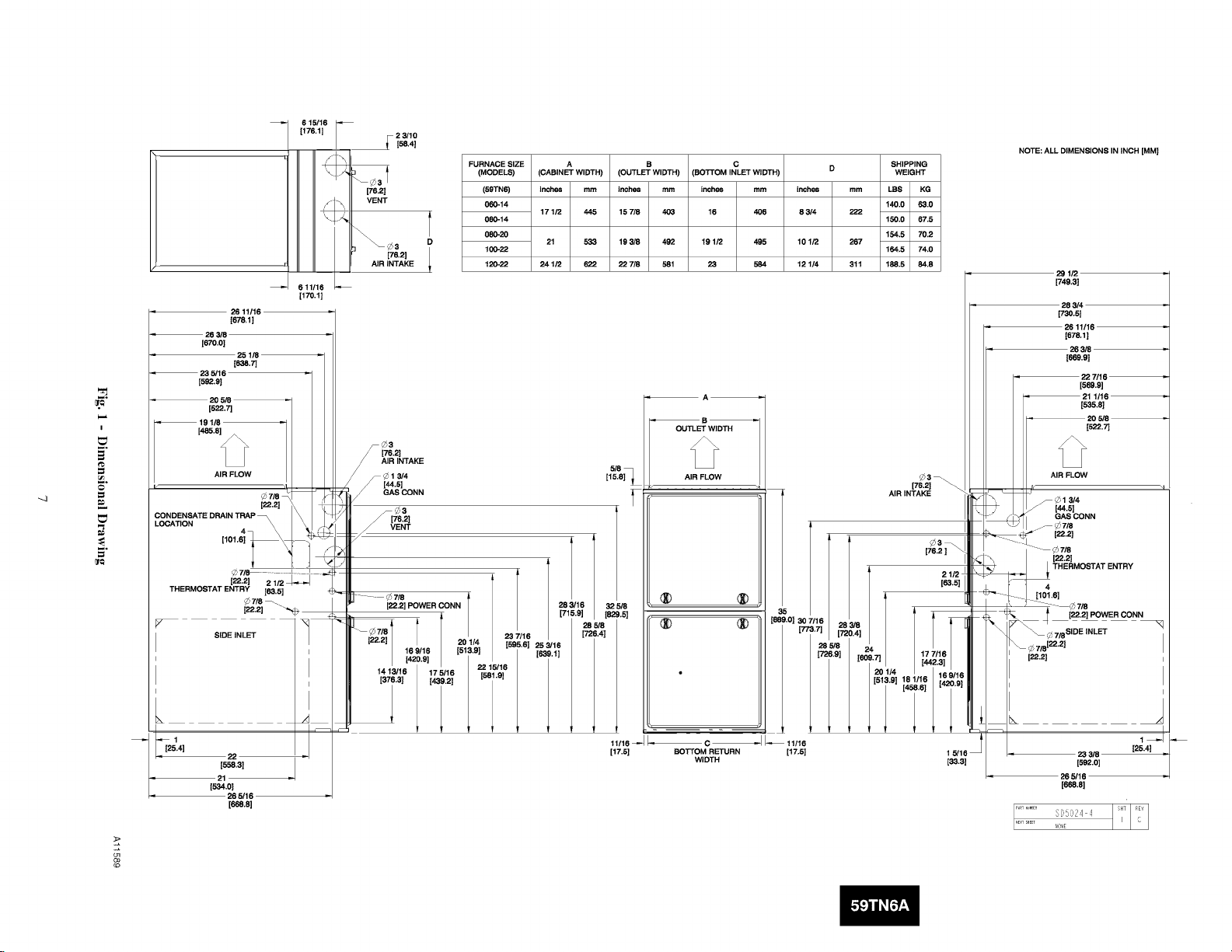
FURNACE SIZE
(MODELS)
(59TN6)
060-14
080=14
D
08_20
100-22
120-22
A S C SHIPPING
(CABINET WIDTH) (OUTLET WIDTH) (BOTTOM INLET WIDTH) D WEIGHT
Inches mm Inches mm inches mm mm LBS KG
171/2 445
21 533
241/2 622
15 7/8 403 16 406
193/8 492 191/2 495
22 7/8 581 23 584
_A_
_B_
OUTLET WIDTH
AIR FLOW
inches
8 3/4
101/2
12 114
140.0 63.0
222
150.0 67.5
154.5 70.2
267
164.5 74.0
311 188.5 84.8
[76.2[
AIR INTAKE
Ill1 =,
NOTE: ALL DIMENSIONS IN INCH [MM]
29 1/2
[749.3]
283/4
173o,51
26 11/16
1678.1 ]
26 3/8
[669.01
227116
[569.8]
1/16
[838.8]
AIR FLOW
_ _ 13/4
[_-61
GAS CONN
.... _/_7/8
[22.2]
.... _7/8
, [22.2]
_ THERMOSTAT ENTRY
4
[101.61
........ _7/8
[ [22.2] POWER CONN
_ 7/8SIDE INLET
_ 7/8122"21 I
L
[25.4]
22
[588,31
21
1834.o1
26 5/16
[SSS.8]
I I 1518.8 181/.166 2_';'!
[17.5] BOTTOM RETURN [17.5[ 1 5/16
WIDTH [33.3]
[22.2]
23 3/8
[6_.oI
26 3/16
1668.81
SD_02,1 ,':
I
[26.41
Page 8

H
AIRFLOW
THE BLOWER IS LOCATED
TOTHE RIGHT OFTHE
BURNER SECTION, AND
AIR CONDiTiONED AiR iS
DISCHARGED TO THE LEFT.
THE BLOWER iS
LOCATED ABOVE TH E
BURNER SECTION, AND
CONDiTiONED AIR IS
DISCHARGED DOWNWARD AIRFLOW
Fig. 2 - Multipoise Orientations
THE BLOWER iS
LOCATED BELOW THE
BURNER SECTION, AND
CONDiTiONED AiR iS
DISCHARGED UPWARD.
AIRFLOW
THE BLOWER iS
LOCATED TO THE LEFT
OF THE BURNER SECTION,
AND CONDiTiONED AiR IS
DISCHARGED TO THE RIGHT.
A02097
SUPPLYAIR
32° F/0 ° C MINIMUM INSTALLED
AMBIENT OR FREEZE
PROTECTION REQUIRED
Fig. 3 - Freeze Protection and Return Air Temperature
FRONT
RETURN
AIR
MAX80 °F / 27°C
MIN60°F / 16°O
A10490
BACK FRONT
Fig. 4 - Prohibited Installations
A10494
18-IN. (457.2 mm)
MINIMUM TO BURNERS
A93044
Fig. 5 - Installation in a Garage
Page 9

AIR FOR COMBUSTION AND
VENTILATION
Introduction
Direct Vent (2-pipe) Applications
When the furnace is installed as a direct vent (2-pipe) furnace, no
special provisions for air for combustion are required. However,
other gas appliances installed in the space with the furnace may
require outside airfor combustion. Follow the guidelines below to
insure thatother gas appliances have sufficient air for combustion.
Non-Direct Vent (1-pipe) Applications
When the furnace is installed as a non-direct vent (l-pipe) furnace,
it will be necessary to insure there is adequate air for combustion.
Other gas appliances installed with the furnace may also require air
for combustion and ventilation in addition to the amount of
combustion air and ventilation air required for the furnace. Follow
the guidelines below to insure that the furnace and other gas
appliances have sufficient air for combustion.
Ventilated Combustion Air Applications
When the furnace is installed using the ventilated combustion air
option, the attic or crawlspace nmst freely communicate with the
outdoor to provide sufficient air for combustion. The combustion
air pipe cannot be terminated in attics or crawlspaces that use
ventilation fans designed to operate during the heating season. If
ventilation fans are present in these areas, the combustion air pipe
nmst terminate outdoors as a Direct Vent/2-Pipe system.
All air for combustion is piped directly to the furnace from a space
that is well ventilated with outdoor air (such as an attic or crawl
space) and the space is well isolated from the living space or
garage. In addition, other gas appliances installed in the space with
the furnace may require outside air for combustion. Follow the
guidelines below to insure that the roof or crawlspace walls have
sufficient free area to provide sufficient air for combustion and
ventilation for the furnaces. The guidelines below can be used to
insure that other gas appliances have sufficient air for combustion.
Provisions for adequate combustion, ventilation, and dilution air
must be provided in accordance with:
• U.S.A. Installations: Section 9.3 of the NFPA 54/ANSI
Z223.1-2009, Air for Combustion and Ventilation and
applicable provisions of the local building codes.
• Canada: Part 8 of the CAN/CSA-B149.1-2010, Venting
Systems and Air Supply for Appliances.
FURNACE CORROSION HAZARD
Failure to follow this caution may result in furnace damage.
Air for combustion nmst not be contaminated by halogen
compounds, which include fluoride, chloride, bromide, and
iodide. These elements can corrode heat exchangers and
shorten furnace life. Air contaminants are found in aerosol
sprays, detergents, bleaches, cleaning solvents, salts, air
fresheners, and other household products.
CARBON MONOXIDE POISONING HAZARD
Failure to follow this warning could result in personal
iniury or death.
The operation of exhaust fans, kitchen ventilation fans,
clothes dryers, attic exhaust fans or fireplaces could create a
NEGATIVE PRESSURE CONDITION at the furnace.
Make-up air MUST be provided for the ventilation devices,
in addition to that required by the furnace. Refer to the
Carbon Monoxide Poisoning Hazard warning in the venting
section of these instructions to determine if an adequate
amount of make-up air is availaMe.
The requirements for combustion and ventilation air depend upon
whether or not the furnace is located in a space having a volume of
at least 50 cubic feet per 1,000 Btuh input rating for all gas
appliances installed in the space.
• Spaces having less than 50 cubic feet per 1,000 Btuh (4.8 cubic
meters per kW) require the Outdoor Combustion Air Method,
• Spaces having at least 50 cubic feet per 1,000 Btuh (4.8 cubic
meters per kW) may use the Indoor Combustion Air,
Standard or Known Air Infiltration Method.
Outdoor Combustion Air Method
1. Provide the space with sufficient air for proper combustion,
ventilation, and dilution of flue gases using permanent hori-
zontal or vertical duct(s) or opening(s) directly communicat-
ing with the outdoors or spaces that freely communicate
with the outdoors.
2. Fig. 6 illustrates how to provide TWO OUTDOOR
OPENINGS, one inlet and one outlet combustion and vent-
ilation air opening, to the outdoors.
a. One opening MUST commence within 12 in. (300 ram)
of the ceiling and the second opening MUST commence
within 12 in. (300 ram) of the floor.
b. Size openings and ducts per Fig. 6 and TaMe 3.
c. TWO HORIZONTAL DUCTS require I sq. in. (645 sq.
ram) of free area per 2,000 Btuh (1,100 mm2/kW) of com-
bined input for all gas appliances in the space per Fig. 6and
Table 3.
d. TWO OPENINGS OR VERTICAL DUCTS require 1
sq. in. (645 sq. ram) of free area per 4,000 Btuh (550
mm2/kW) for combined input of all gas appliances in the
space per Fig. 6 and Table 3.
3. ONE OUTDOOR OPENING requires:
a. 1 sq. in. (645 sq. ram) of free area per 3,000 Btuh (734
mm2/kW) for combined input of all gas appliances in the
space per Fig. 6 and Table 3.
b. Not less than the sum of the areas of all vent connectors in
the space.
The opening shall commence within 12 in. (300 ram) of the
ceiling. Appliances in the space shall have clearances of at least 1
in. (25 ram) from the sides and back and 6 in. (150 ram) from the
front. The opening shall directly communicate with the outdoors or
shall conmmnicate through a vertical or horizontal duct to the
outdoors or spaces (crawl or attic) that freely communicate with the
outdoors.
ii
Page 10

ii
Indoor Combustion Air© NFPA & AGA
Standard and Known-Air-Infiltration Rate Methods
Indoor air is pernfitted for combustion, ventilation, and dilution, if
the Standard or Known-Air-Infiltration Method is used.
CARBON MONOXIDE POISONING HAZARD
Failure to follow this warning could result in personal
iniury or death.
Many homes require air to be supplied from outdoors
for furnace combustion, ventilation, and dilution of flue
gases.
The furnace combustion air supply must be provided in
accordance with this instruction manual.
Standard Method
1. The space has no less volume than 50 cubic feet per 1,000
Btuh of the maximum input ratings for all gas appliances
installed in the space and
2. The air infiltration rate is not known to be less than 0.40 air
changes per hour (ACH).
The Known Air Infiltration Rate Method shall be used, if the
infiltration rate is known to be:
1. Less than 0.40 ACH and
2. Equal to or greater than 0.10 ACH
Infiltration rates greater than 0.60 ACH shall not be used. The
minimum required volume of the space varies with the number of
ACH and shall be deternfined per Table 4 or Equations 1 and 2.
Deternfine the minimum required volume for each appliance in the
space and add the volumes together to get the total minimum
required volume I\_r the space.
Table 4 - Minimum Space Volumes were deternfined by using the
following equations from the current edition of the National Fuel
Gas Code ANSI Z223.1/NFPA 54, 9.3.2.2:
1. For other than fan-assisted appliances, such as a draft
hood-equipped water heater:
Volume _ 21ft3 ("- !other __
Other ACH _000 Btu/hrJ
A04002
2. For fan-assisted appliances such as this furnace:
of the floor. The minimum dimension of air openings shall
be at least 3 in. (80 ram). (See Fig. 7.)
c. Combining space on different floor levels. The volumes of
spaces on different floor levels shall be considered as com-
municating spaces if connected by one or more permanent
openings in doors or floors having free area of at least 2
in.2/1,000 Btuh (4,400 mm2/kW) of total input rating of
all gas appliances.
2. An attic or crawlspace may be considered a space that freely
communicates with the outdoors provided there are ad-
equate permanent ventilation openings directly to outdoors
having free area of at least 1-in.2/4,000 Btuh of total input
rating for all gas appliances in the space.
3. In spaces that use the Indoor Combustion Air Method, in-
filtration should be adequate to provide air for combustion,
permanent ventilation and dilution of flue gases. However,
in buildings with unusually tight construction, additional air
MUST be provided using the methods described in the
Outdoor Combustion Air Method section.
4. Unusually tight construction is defined as Construction
with:
a. Walls and ceilings exposed to the outdoors have a continu-
ous, sealed vapor barrier. Openings are gasketed or sealed
and
b. Doors and openable windows are weatherstripped and
c. Other openings are caulked or sealed. These include joints
around window and door frames, between sole plates and
floors, between wall-ceiling joints, between wall panels,
at penetrations for plumbing, electrical and gas lines, etc.
Combination of Indoor and Outdoor Air
1. Indoor openings shall comply with the Indoor Combus-
tion Air Method below and,
2. Outdoor openings shall be located as required in the Out-
door Combustion Air Method mentioned previously and,
3. Outdoor openings shall be sized as follows:
a. Calculate the Ratio of all Indoor Space volume divided by
required volume for Indoor Combustion Air Method be-
low.
b. Outdoor opening size reduction Factor is I nfinus the Ra-
tio in a. above.
c. Minimum size of Outdoor openings shall be the size re-
quired in Outdoor Combustion Air Method above multi-
plied by reduction Factor in b. above. The minimum di-
mension of air openings shall be not less than 3 in. (80 ram).
Volume _ 15ft 3 ("_ I _ _'_
Fan ACH _000" Btu/hr/
If: Iother = combined input of all other than fan-assisted appliances
in Btuh/hr
Ifan = combined input of all fan-assisted appliances in Btuh/hr
ACH = air changes per hour (ACH shall not exceed 0.60.)
The following requirements apply to the Standard Method and to
the Known Air Infiltration Rate Method.
1. Adjoining rooms can be considered part of a space if:
a. There are no closeable doors between rooms.
b. Combining spaces on same floor level. Each opening shall
have free area of at least I in.2/1,000 Btuh (2,000 mm2/kW)
of the total input rating of all gas appliances in the space,
but not less than 100 in. 2 (0.06 m2). One opening shall
commence within 12 in. (300 ram) of the ceiling and the
second opening shall commence within 12 in. (300 ram)
J
A04003
10
Page 11
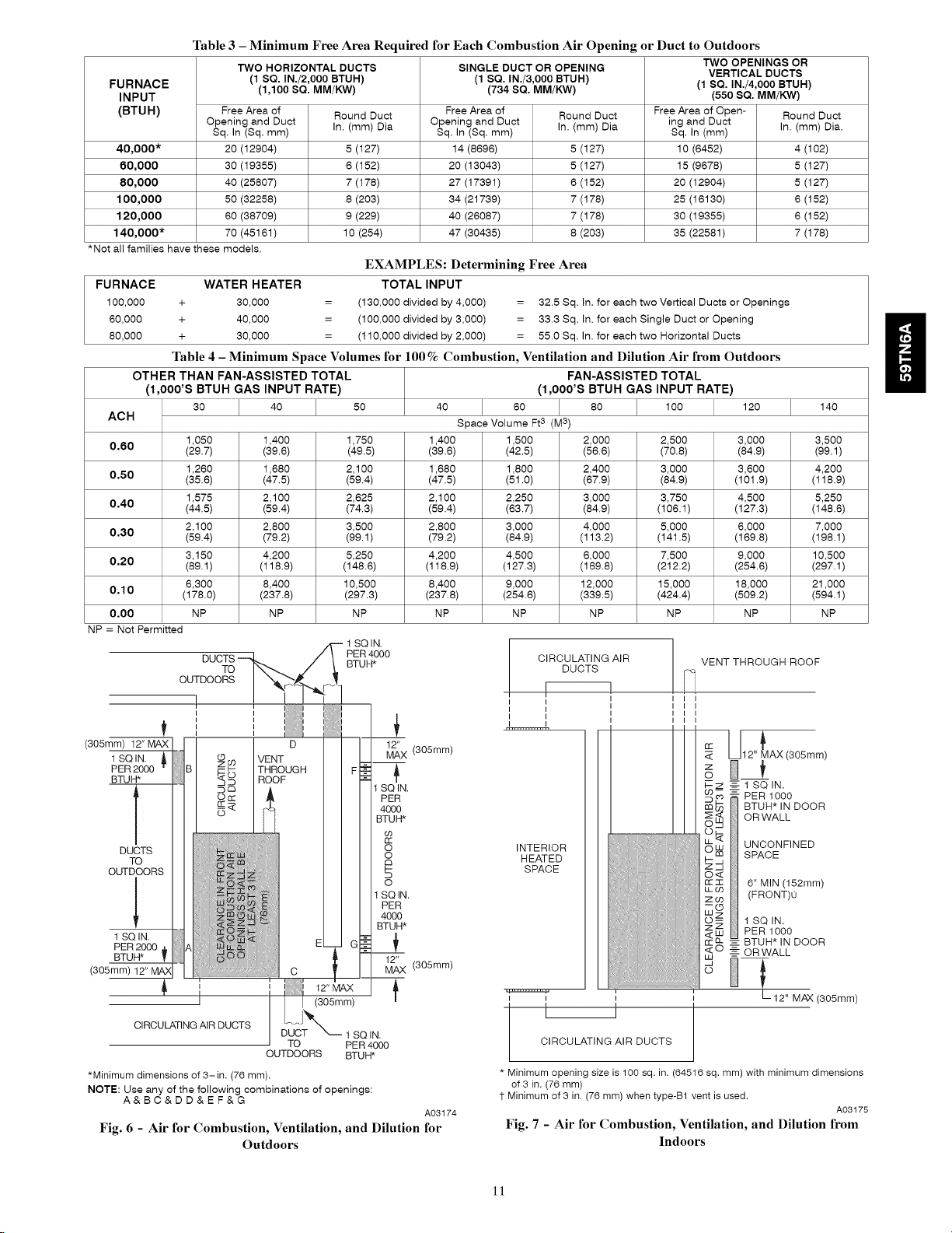
Table 3 - Minimum Free Area Required for Each Combustion Air Opening or Duct to Outdoors
TWO HORIZONTAL DUCTS SINGLE DUCT OR OPENING TWO OPENINGS OR
FURNACE (1,100 SQ. MM/KW) (734 SQ. MM/KW) (1 SQ. IN./4,000 BTUH)
INPUT (550 SQ. MM/KW)
(BTUH) Free Area of Round Duct Free Area of Round Duct Free Area of Open- Round Duct
40,000* 20 (12904) 5 (127) 14 (8696) 5 (127) 10 (6452) 4 (102)
60,000 30 (19355) 6 (152) 20 (13043) 5 (127) 15 (9678) 5 (127)
80,000 40 (25807) 7 (178) 27 (17391) 6 (152) 20 (12904) 5 (127)
100,000 50 (32258) 8 (203) 34 (21739) 7 (178) 25 (16130) 6 (152)
120,000 60 (38709) 9 (229) 40 (26087) 7 (178) 30 (19355) 6 (152)
140,000" 70 (45161) 10 (254) 47 (30435) 8 (203) 35 (22581) 7 (178)
*Not all families have these models.
FURNACE WATER HEATER TOTAL INPUT
100,000 + 30,000 = (130,000 divided by 4,000) = 32.5 Sq. In. for each two Vertical Ducts or Openings
60,000 + 40,000 = (100,000 divided by 3,000) = 33.3 Sq. In. for each Single Duct or Opening
80,000 + 30,000 = (110,000 divided by 2,000) = 55.0 Sq, In. for each two Horizontal Ducts
Table 4 - Minimum Space Volumes for 100 % Combustion, Ventilation and Dilution Air from Outdoors
OTHER THAN FAN-ASSISTED TOTAL FAN-ASSISTED TOTAL
(1,000'S BTUH GAS INPUT RATE) (1,000'S BTUH GAS INPUT RATE)
30 40 50 40 60 80 100 120 140
ACH Space Volume Ft3 (M3)
0,60 (29.7) (39.6) (49.5) (39.6) (42.5) (56.6) (70.8) (84.9) (99.1)
0,50 (35.6) (47.5) (59.4) (47.5) (51.0) (67.9) (84.9) (101.9) (118.9)
0,40 (44.5) (59.4) (74.3) (59.4) (63.7) (84.9) (106.1 ) (127.3) (148.6)
0,30 (59.4) (79.2) (99.1) (79.2) (84.9) (113.2) (141.5) (169.8) (198.1 )
0.20 (89.1) (118.9) (148.6) (118.9) (127.3) (169.8) (212.2) (254.6) (297.1)
0.10 (178.0) (237.8) (297.3) (237.8) (254.6) (339.5) (424.4) (509.2) (594.1)
0,00 NP NP NP NP NP NP NP NP NP
NP = Not Permitted
1,050 1,400 1,750 1,400 1,500 2,000 2,500 3,000 3,500
1,260 1,680 2,100 1,680 1,800 2,400 3,000 3,600 4,200
1,575 2,100 2,625 2,100 2,250 3,000 3,750 4,500 5,250
2,100 2,800 3,500 2,800 3,000 4,000 5,000 6,000 7,000
3,150 4,200 5,250 4,200 4,500 6,000 7,500 9,000 10,500
6,300 8,400 10,500 8,400 9,000 12,000 15,000 18,000 21,000
OUTDOORSI "._,_._
_ I I ! JJ }i
(305mm) 12"MAX] ]1 I D II 1-_
1sa,a &/ I _o IVENT k-l_
PER2000 "/ ;IBI _ _ ITHROUGH FI:_
BTUFF !i I <;5 I ROOF F_ql S._
,' //I II I1£'"
DUOTS// II 8
, _:
.uT;°ORS// II
..........NN N ',
// II,so
// I II 40(
1SQN /J I _ _ = _M ,
PER 2000 ,_/'IAI _ _ 7- _:_--
BTUFF T :0
*Minimum dimensions of 3-in. (76 mm).
NOTE: Use any of the following combinations of openings:
Fig. 6 - Air for Combustion, Ventilation, and Dilution for
! J I i i BTL
i .......... _ L L_P=-I
A l i i 12"MAX/
OROULAT,.GA,RDUCTS J\
A&BC&DD&EF&G
(1 SQ. IN./2,000 BTUH) (1 SQ. IN./3,000 BTUH) VERTICAL DUCTS
Opening and Duct Opening and Duct ing and Duct
Sq, In (Sq, mm) In. (mm) Dia Sq, In (Sq, mm) In. (mm) Dia Sq, In (mm) In. (mm) Dia.
EXAMPLES: Determining Free Area
-- 1 SQIN.
Duss-h / °TU.
PER 4000
o
12
(305mm)
(305mm)
CIRCULATING AiR
I I
1 1
I I
INTERIOR
HEATED
SPACE
DUCTS
VENT THROUGH ROOF
I I
I I
_: 12" AX(S05mm)
o
-_- 1 SQ IN.
PER 1000
BTUH* IN DOOR
OR WALL
UNCONFINED
SPACE
6" MIN (152mm)
(FRONT)0
1 SQ IN.
PER 1000
BTUH* IN DOOR
-- OR WALL
12" MAX (305mm)
r(305mm)"
:_8TX_ 1so,..
I TO PER 4000
OUTDOORS BTUH*
Outdoors
A03174
CIRCULATING AIR DUCTS
l'
* Minimum opening size is 100 sq. in. (64516 sq. mm) with minimum dimensions
of 3 in. (76 mm)
1-Minimum of 3 in. (76 mm) when type-B1 vent is used.
Fig. 7 - Air for Combustion, Ventilation, and Dilution from
Indoors
A03175
11
Page 12
ii
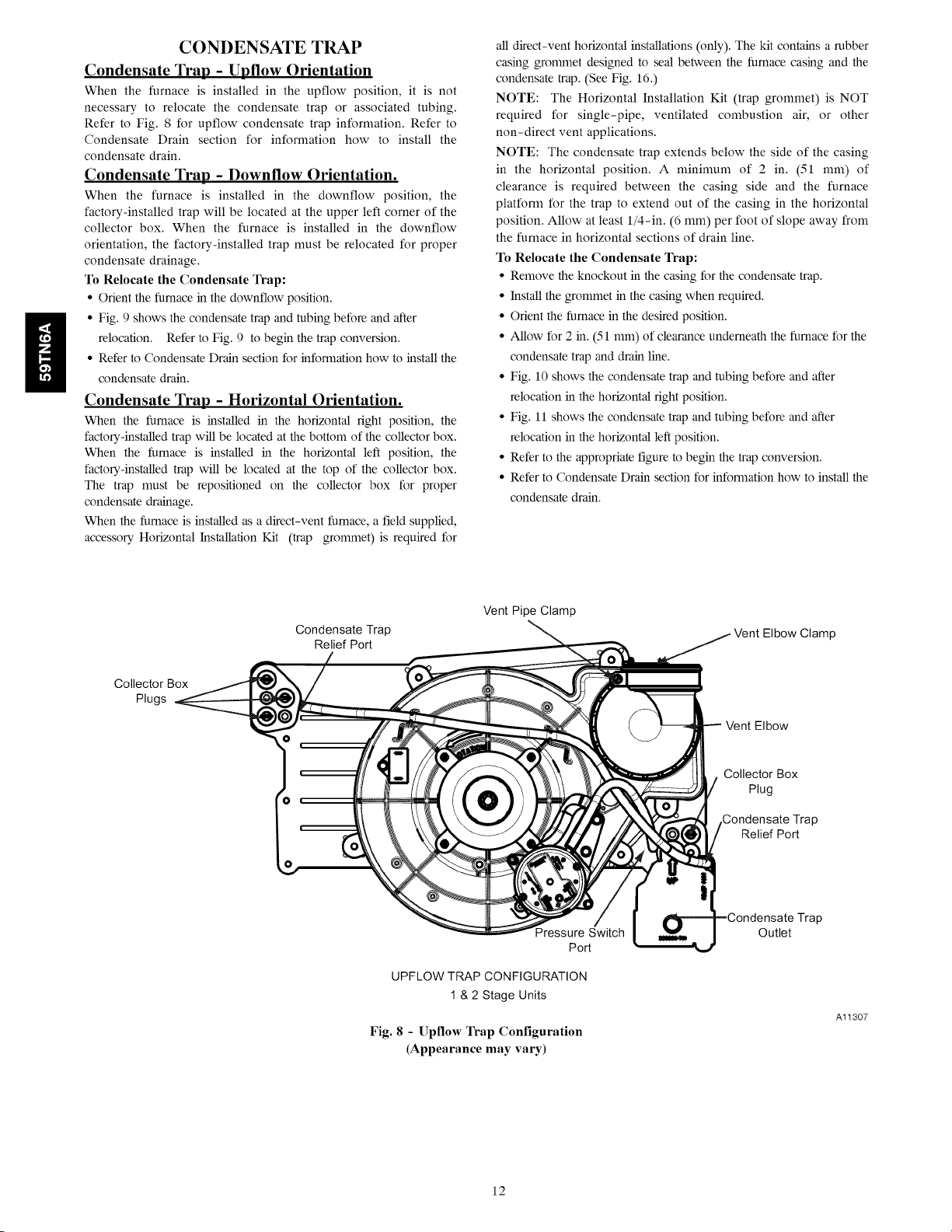
CONDENSATE TRAP
Condensate Trap - Upflow Orientation
When the furnace is installed in the upflow position, it is not
necessary to relocate the condensate trap or associated tubing.
Refer to Fig. 8 for upflow condensate trap information. Refer to
Condensate Drain section for information how to install the
condensate drain,
Condensate Trap - Downflow Orientation.
When the furnace is installed in the downflow position, the
factory-installed trap will be located at the upper left corner of the
collector box. When the furnace is installed in the downflow
orientation, the factory-installed trap must be relocated for proper
condensate drainage,
To Relocate the Condensate Trap:
• Orient the fllmace in the downflow position.
• Fig. 9 shows the condensate trap and tubing before and after
relocation, Refer to Fig. 9 to begin the trap conversion,
• Refer to Condensate Drain section for infomaation how to install the
condensate drain,
Condensate Trap - Horizontal Orientation.
When the fl_mace is installed in the horizontal right position, the
factory-installed trap will be located at the bottom of the collector box.
When the fl_mace is installed in the horizontal left position, the
factory-installed trap will be located at the top of the collector box.
The trap must be repositioned on the collector box for proper
condensate drainage.
When the furnace is installed as a direct-vent furnace, a field supplied,
accessory Horizontal Installation Kit (trap grommet) is required for
all direct-vent horizontal installations (only). The kit contains a rubber
casing grommet designed to seal between the furnace casing and the
condensate trap. (See Fig. 16.)
NOTE: The Horizontal Installation Kit (trap grommet) is NOT
required for single-pipe, ventilated combustion air, or other
non-direct vent applications.
NOTE: The condensate trap extends below the side of the casing
in the horizontal position. A minimum of 2 in. (51 mm) of
clearance is required between the casing side and the furnace
platform for the trap to extend out of the casing in the horizontal
position. Allow at least 1/4-in. (6 mm) per foot of slope away from
the furnace in horizontal sections of drain line.
To Relocate the Condensate Trap:
• Remove the knockout in the casing for the condensate trap.
• Install the grommet in the casing when required.
• Orient the fl_mace in the desired position.
• Allow for 2 in. (51 mm) of clearance underneath the fllmace for the
condensate trap and drain line.
• Fig. 10 shows the condensate trap and tubing before and after
relocation in the horizontal right position.
• Fig. 11 shows the condensate trap and tubing before and after
relocation in the horizontal left position.
• Refer to the appropriate figure to begin the trap conversion,
• Refer to Condensate Drain section for infom_ation how to install the
condensate drain,
Collector Box
Plugs
Condensate Trap
Relief Port
Fig. 8 - Upllow Trap Configuration
Vent Pipe Clamp
Pressure Switch
UPFLOW TRAP CONFIGURATION
1 & 2 Stage Units
(Appearance may vary)
Clamp
Vent Elbow
Collector Box
Plug
Condensate Trap
Relief Port
Trap
Outlet
Port
Al1307
12
Page 13
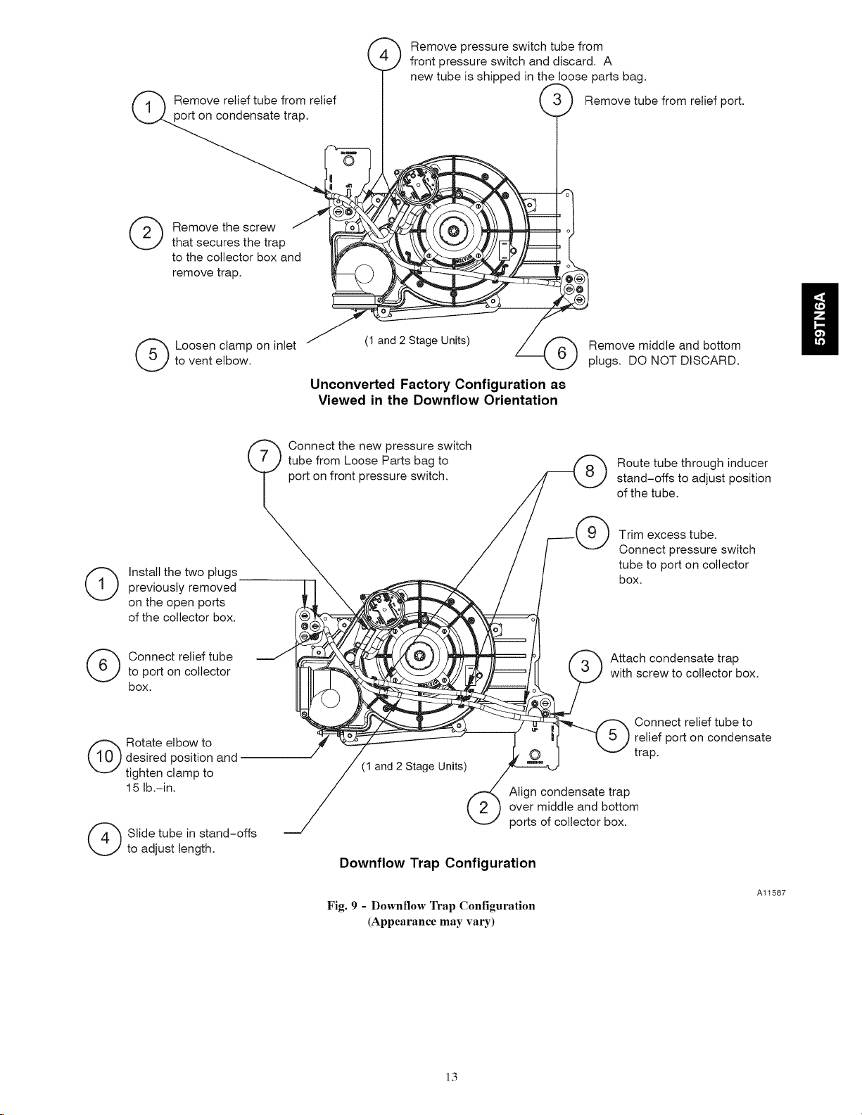
Remove relief tube from relief
port on condensate trap.
._ Remove pressure switch tube from
front pressure switch and discard. A
new tube is shipped in the loose parts bag.
,'}_) Remove tube from relief port.
(_ emove the screw
(_) nstall the two plugs
previously removed
on the open ports
of the collector box.
that secures the trap
to the collector box and
remove trap.
to vent elbow.
(_ Loosen clamp on inlet
(1 and 2 Stage Units)
Remove middle and bottom
plugs. DO NOT DISCARD.
Unconverted Factory Configuration as
Viewed in the Downflow Orientation
Connect the new pressure switch
tube from Loose Parts bag to /f_ Route tube through inducer
port on front pressure switch. _ stand-offs to adjust position
/ _ of the tube.
/ / .| N J Trim excess tube.
/ / Sk"J Connect Pressure switch
/ / / tube to port on collector
_,_ _=_ _ ' / 1 box.
(_ Connect relief tube
to port on collector
box.
desired position and
(_ otate elbow to
tighten clamp to
15 lb.-in.
(_ Slide tube in stand-offs
to adjust length.
_ _/(_)_ _/_ f_ Attach condensate trap
_.\__ -_ IP===t II \ 'J J with screw to collector box.
__ _ Connect relief tube to
____------- relief port on condensate
" J,,O I "-I trap.
(1 and 2 Stage Units) /_
Downflow Trap Configuration
Fig. 9 - Downflow Trap Configuration
(Appearance may vary)
/
Align condensate trap
ports of collector box.
Al1587
13
Page 14

collector box.
(_ emove plug from
DO NOT DISCARD.
If alternate vent position
is required, loosen clamp
on inlet of vent elbow.
ii
As Viewed in the Horizontal Right Orientation
NOTE: Remove knockout in
casing before re-installing the
condensate trap.
trap with screw to
(_ ttach condensate
collector box.
1_ Remove the screw that secures
(1 AND 2 STAGE UNITS)
Unconverted Factory Configuration
the trap to the collector box and
remove trap.
Slide relief tube in stand-offs
to adjust length.
Vent elbow shown in alternate
orientation. Tighten clamp on
inlet to vent elbow 15 lb.-in.
open port of
(_) nstall plug on
collector box
(1 AND 2 STAGE UNITS)
Horizontal Right Trap Configuration
Fig. 10 - Horizontal Right Trap Configuration
(Appearance may vary)
14
Align trap over middle and
right-hand port on collector box.
Al1573
Page 15

If alternate vent position
is required, loosen clamp
on vent elbow inlet.
from port on collector --
(_ emove relief tube
box.
(1 AND 2 STAGE UNITS)
Remove the screw that secures the
condensate trap to the collector box
and remove trap.
Remove relief tube from
relief port on condensate
trap.
Remove front pressure
switch tube and discard.
A new tube is shipped in
the Loose Parts bag.
H
Remove middle and right
plug from collector box.
DO NOT DISCARD.
NOTE: Remove knockout in
casing before re-installing the
condensate trap.
(_ Rotate elbow to
desired position
and torque clamp
on inlet 15 lb.-in.
(_ Slide relief tube instand-offs to adjust
length.
(_ ttach condensatetrap with screw to
collector box.
(_ Align trap over middleand right-hand port on
collector box.
Unconverted Factory Trap Configuration
As Viewed in the Horizontal Left Orientation
Install two plugs previously
removed in open ports on
collector box.
Connect relief tube to port
on collector box.
Connect the new pressure switch
tube from Loose Parts bag to port
on front pressure switch.
\
(1 AND 2 STAGE UNITS)
Route pressure switch tube
underneath relief tube and
connect to port on
collector box.
Connect relief tube to relief
port on condensate trap.
Horizontal Left Trap Configuration
Fig. ll - Horizontal Left Configuration
(Appearance may vary)
15
Al1574
Page 16
H
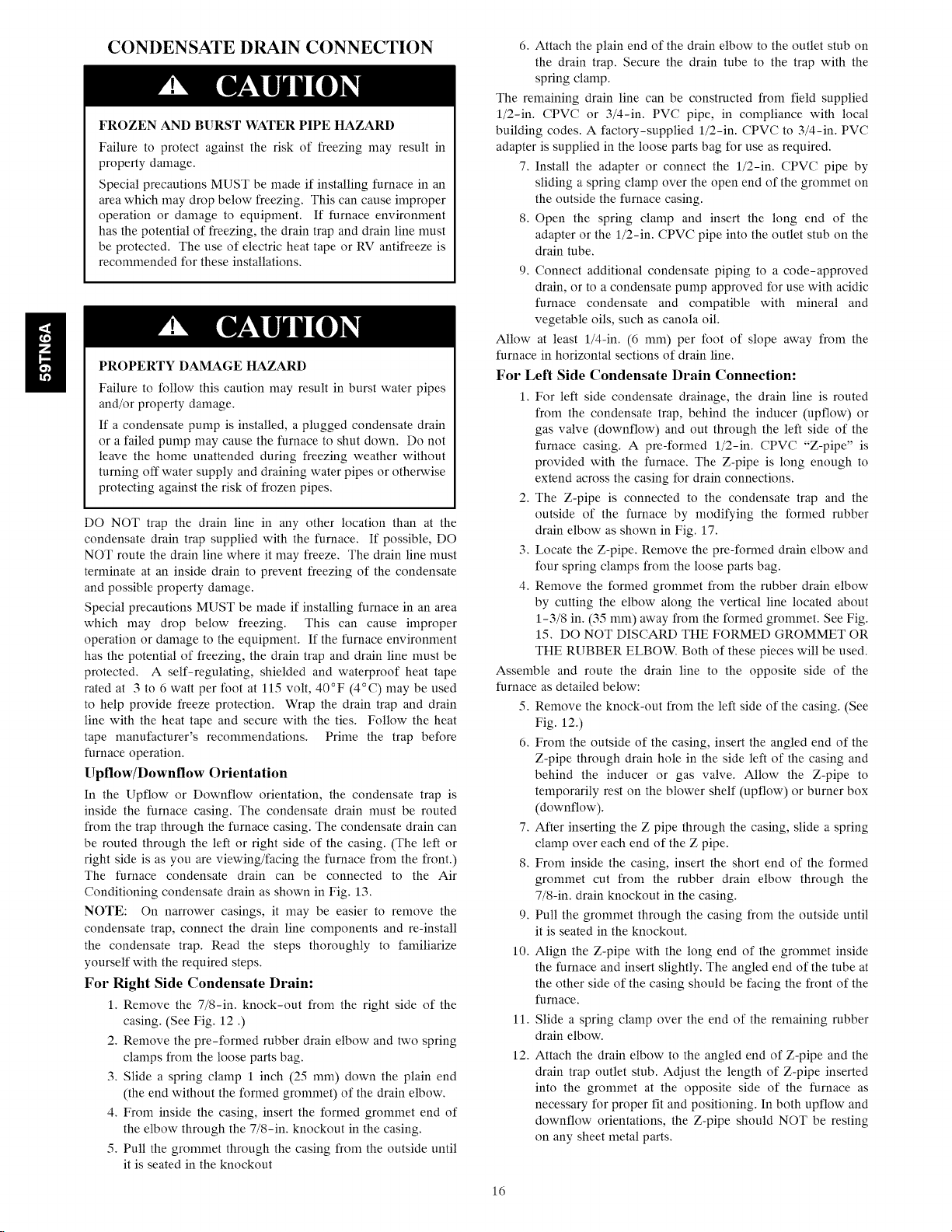
CONDENSATE DRAIN CONNECTION
FROZEN AND BURST WATER PIPE HAZARD
Failure to protect against the risk of freezing may result in
property damage.
Special precautions MUST be made if installing furnace in an
area which may drop below freezing. This can cause improper
operation or damage to equipment. If furnace environment
has the potential of freezing, the drain trap and drain line must
be protected. The use of electric heat tape or RV antifreeze is
recommended for these installations.
PROPERTY DAMAGE HAZARD
Failure to follow this caution may result in burst water pipes
and/or property damage.
If a condensate pump is installed, a plugged condensate drain
or a failed pump may cause the furnace to shut down. Do not
leave the home unattended during freezing weather without
turning off water supply and draining water pipes or otherwise
protecting against the risk of frozen pipes.
DO NOT trap the drain line in any other location than at the
condensate drain trap supplied with the furnace. If possible, DO
NOT route the drain line where it may freeze. The drain line must
terminate at an inside drain to prevent freezing of the condensate
and possible property damage.
Special precautions MUST be made if installing furnace in an area
which may drop below freezing. This can cause improper
operation or damage to the equipment. If the furnace environment
has the potential of freezing, the drain trap and drain line must be
protected. A self-regulating, shielded and waterproof heat tape
rated at 3 to 6 watt per foot at 115 volt, 40°F (4°C) may be used
to help provide freeze protection. Wrap the drain trap and drain
line with the heat tape and secure with the ties. Follow the heat
tape manufacturer's recommendations. Prime the trap before
furnace operation.
Upflow/Downflow Orientation
In the Upflow or Downflow orientation, the condensate trap is
inside the furnace casing. The condensate drain must be routed
from the trap through the furnace casing. The condensate drain can
be routed through the left or right side of the casing. (The left or
right side is as you are viewing/facing the furnace from the front.)
The furnace condensate drain can be connected to the Air
Conditioning condensate drain as shown in Fig. 13.
NOTE: On narrower casings, it may be easier to remove the
condensate trap, connect the drain line components and re-install
the condensate trap. Read the steps thoroughly to familiarize
yourself with the required steps.
For Right Side Condensate Drain:
1. Remove the 7/8-in. knock-out from the right side of the
casing. (See Fig. 12 .)
2. Remove the pre-formed rubber drain elbow and two spring
clamps from the loose parts bag.
3. Slide a spring clamp 1 inch (25 mm) down the plain end
(the end without the formed grommet) of the drain elbow.
4. From inside the casing, insert the formed grommet end of
the elbow through the 7/8-in. knockout in the casing.
5. Pull the grommet through the casing from the outside until
it is seated in the knockout
6. Attach the plain end of the drain elbow to the outlet stub on
the drain trap. Secure the drain tube to the trap with the
spring clamp.
The remaining drain line can be constructed from field supplied
l/2-in. CPVC or 3/4-in. PVC pipe, in compliance with local
building codes. A factory-supplied l/2-in. CPVC to 3/4-in. PVC
adapter is supplied in the loose parts bag for use as required.
7. Install the adapter or connect the l/2-in. CPVC pipe by
sliding a spring clamp over the open end of the grommet on
the outside the furnace casing.
8. Open the spring clamp and insert the long end of the
adapter or the l/2-in. CPVC pipe into the outlet stub on the
drain tube.
9. Connect additional condensate piping to a code-approved
drain, or to a condensate pump approved for use with acidic
furnace condensate and compatible with mineral and
vegetable oils, such as canola oil.
Allow at least l/4-in. (6 mm) per foot of slope away from the
furnace in horizontal sections of drain line.
For Left Side Condensate Drain Connection:
1. For left side condensate drainage, the drain line is routed
from the condensate trap, behind the inducer (upflow) or
gas valve (downflow) and out through the left side of the
furnace casing. A pre-formed l/2-in. CPVC "Z-pipe" is
provided with the furnace. The Z-pipe is long enough to
extend across the casing for drain connections.
2. The Z-pipe is connected to the condensate trap and the
outside of the furnace by modifying the formed rubber
drain elbow as shown in Fig. 17.
3. Locate the Z-pipe. Remove the pre-formed drain elbow and
four spring clamps from the loose parts bag.
4. Remove the formed grommet from the rubber drain elbow
by cutting the elbow along the vertical line located about
1-3/8 in. (35 mm) away from the formed grommet. See Fig.
15. DO NOT DISCARD THE FORMED GROMMET OR
THE RUBBER ELBOW. Both of these pieces will be used.
Assemble and route the drain line to the opposite side of the
furnace as detailed below:
5. Remove the knock-out from the left side of the casing. (See
Fig. 12.)
6. From the outside of the casing, insert the angled end of the
Z-pipe through drain hole in the side left of the casing and
behind the inducer or gas valve. Allow the Z-pipe to
temporarily rest on the blower shelf (upflow) or burner box
(downflow).
7. After inserting the Z pipe through the casing, slide a spring
clamp over each end of the Z pipe.
8. From inside the casing, insert the short end of the formed
grommet cut from the rubber drain elbow through the
7/8-in. drain knockout in the casing.
9. Pull the grommet through the casing from the outside until
it is seated in the knockout.
10. Align the Z-pipe with the long end of the grommet inside
the furnace and insert slightly. The angled end of the tube at
the other side of the casing should be facing the front of the
furnace.
11. Slide a spring clamp over the end of the remaining rubber
drain elbow.
12. Attach the drain elbow to the angled end of Z-pipe and the
drain trap outlet stub. Adjust the length of Z-pipe inserted
into the grommet at the opposite side of the furnace as
necessary for proper fit and positioning. In both upflow and
downflow orientations, the Z-pipe should NOT be resting
on any sheet metal parts.
16
Page 17
13.SecuretherubberelbowtothedraintrapandtheZ-pipe
withspringclamps.
14.SecurethegrommettotheZ-pipewiththespringclamp.
Theremainingdrainlinecanbeconstructedfromfieldsupplied
l/2-in.CPVCor3/4-in.PVCpipe,incompliancewithlocal
buildingcodes.Afactory-suppliedl/2-in.CPVCto3/4-in.PVC
adapterissuppliedintheloosepartsbagforuseasrequired.
15.Installtheadapterorconnectthel/2-in.CPVCpipeby
slidingaspringclampovertheopenendofthegrommeton
theoutsidethefurnacecasing.
16.Openthespringclampandinsertthelongendof the
adapterorthel/2-in.CPVCpipeintotheoutletstubonthe
draintube.
17.Connectadditionalcondensatepipingtoacode-approved
drain,ortoacondensatepumpapprovedforusewithacidic
furnacecondensateandcompatiblewithmineraland
vegetableoils,suchascanolaoil.
Allow at least l/4-in. (6 mm) per foot of slope away from the fur-
nace in horizontal sections of drain line.
Horizontal Orientation
1. In the Horizontal orientation, a field supplied accessory
drain trap grommet is required to seal the gap between the
casing and the condensate trap for direct vent applications,
only. The grommet is NOT required for single-pipe, or oth-
er non-direct-vent applications.
2. The condensate trap outlet extends 2 in. (51 ram) below the
furnace casing. To allow for servicing the trap, the
condensate drain tube in the loose parts bag can be modified
to make a coupler to allow for future service of the
condensate trap and drain line.
3. Remove the knock-out for the condensate trap in the side of
the casing.
4. Install the drain trap grommet in the casing if required for
direct vent applications. If necessary, remove the trap, install
the grommet and re-install the trap.
5. Remove the pre-formed rubber drain elbow, and two spring
clamps from the loose parts bag.
6. Remove the formed grommet on the elbow to create an
elbow or straight connector. (See Fig. 15.)
7. Connect the cut elbow or grommet to the outlet of the
condensate trap with 1 spring clamp.
The remaining drain line can be constructed from field-supplied
l/2-in. CPVC or 3/4-in. PVC pipe, in compliance with local build-
ing codes. A factory-supplied l/2-in. CPVC to 3/4-in. PVC adapter
is supplied in the loose parts bag for use as required.
8. Install the adapter or connect the l/2-in. CPVC pipe by
sliding a spring clamp over the open end of the elbow or
grommet on the outside the furnace casing.
9. Open the spring clamp and insert the long end of the
adapter or the 1/2-in. CPVC pipe into the outlet stub on the
drain tube.
10. Connect additional condensate piping to a code-approved
drain, or to a condensate pump approved for use with acidic
furnace condensate and compatible with mineral and
vegetable oils, such as canola oil.
Allow at least 1/4-in. (6 ram) per foot of slope away from the
furnace in horizontal sections of drain line.
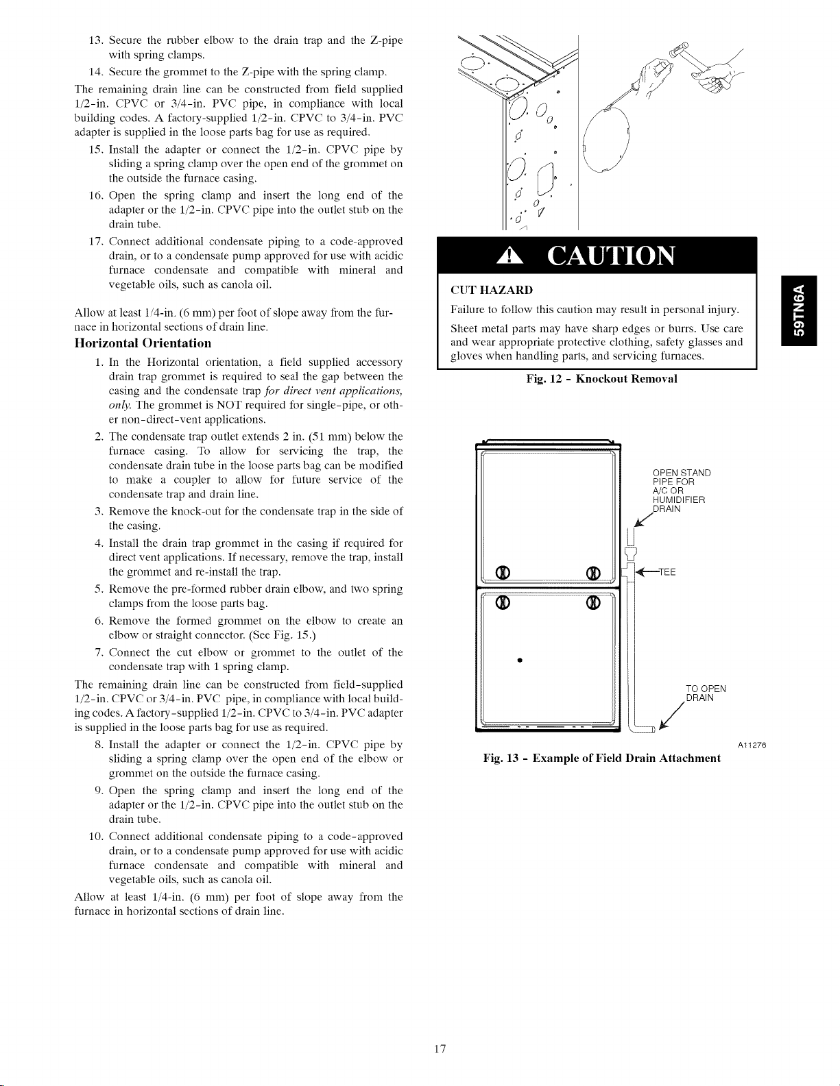
CUT HAZARD
Failure to follow this caution may result in personal iniury.
Sheet metal parts may have sharp edges or burrs. Use care
and wear appropriate protective clothing, safety glasses and
gloves when handling parts, and servicing furnaces.
Fig. 12 - Knockout Removal
OPENSTAND
PiPEFOR
A/COR
HUMIDIFIER
DRAIN
U
_T----TE E
TOOPEN
DRAIN
Fig. 13 - Example of Field Drain Attachment
H
Al1276
17
Page 18
INSTALL CLAMPS ON DRAIN TUBE
ATTACH DRAIN TUBE TO CONDENSATE?
DRAIN TRAP
PULL DRAIN STUB /
THROUGH CASING / /
/' / "_\
' : / \
OPEN SPRING CLAMP
INSERT FACTORY-SUPPLIED 1/2-1N. CPVC
TO 3/4-1N. PVC ADAPTER OR 1/2-iN CPVC PtPE
*CLAMP MAY BE LOCATED ON OUTSIDE OF DRAIN
TUBE
RIGHT SiDE DRAIN iNSTALLATiON
/ \
/
/ _,
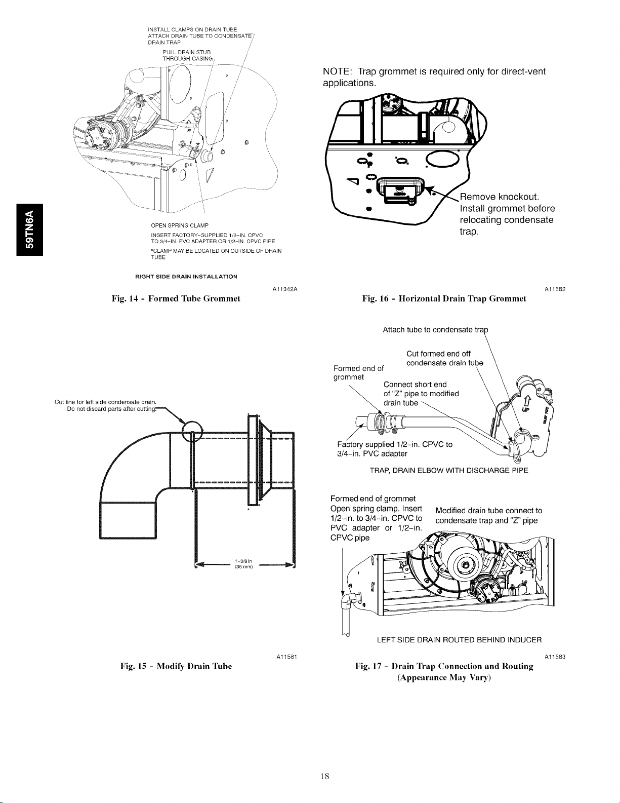
Fig. 14 - Formed Tube Grommet
/
NOTE: Trap grommet is required only for direct-vent
applications.
J
/
Remove knockout,
Install grommet before
relocating condensate
trap.
Al1342A
Fig. 16 - Horizontal Drain Trap Grommet
Al1582
Cut line for left side condensate drain.
Do not disc
l !
Attach tube to condensate
Cut formed end off
Formed end of
grommet
of "Z" pipe to modified
condensate drain tube
Connect short end
ube
Factory supplied 1/2-in. CPVC to
3/4-in. PVC adapter
TRAP, DRAIN ELBOW WITH DISCHARGE PIPE
T
Formed end of grommet
Open spring clamp. Insert
1/2-in. to 3/4-in. CPVC to
PVC adapter or 1/2-in.
Modified drain tube connect to
condensate trap and "Z" pipe
CPVC pipe
1-3/8 in
(35 ram)
Fig. 15 - Modify Drain 1hbe
Al1581
LEFT SIDE DRAIN ROUTED BEHIND INDUCER
Al1583
Fig. 17 - Drain Trap Connection and Routing
(Appearance May Vary)
18
Page 19

INSTALLATION
NOTE: This furnace is certified to leak 2% or less of nominal air
conditioning CFM delivered when pressurized to 1-inch water
column with all present air inlets, air outlets, and plumbing and
electrical ports sealed, including bottom closure in upflow and
horizontal applications.
Upflow Installation
NOTE: The furnace must be pitched as shown in Fig. 23 for
proper condensate drainage.
Supply Air Connections
For a furnace not equipped with a cooling coil, the outlet duct shall
be provided with a removable access panel. This opening shall be
accessible when the furnace is installed and shall be of such a size
that the heat exchanger can be viewed for possible openings using
light assistance or a probe can be inserted for sampling the air
stream. The cover attachment shall prevent leaks.
Connect supply-air duct to flanges on furnace supply-air outlet.
Bend flange upward to 90 ° with wide duct pliers. (See Fig. 20.)
The supply-air duct must be connected to ONLY the furnace
supply-outlet-air duct flanges or air conditioning coil casing
(when used). DO NOT cut main furnace casing side to attach
supply air duct, humidifier, or other accessories. All accessories
MUST be connected to duct external to furnace main casing.
Return Air Connections
FIRE HAZARD
A failure to follow this warning could cause personal injury,
death and/or property damage.
Never connect return-air ducts to the back of the furnace.
Follow instructions below.
To install leveling legs:
1. Position furnace on its back. Locate and drill a hole in each
bottom corner of furnace.
2. For each leg, install nut on bolt and then install bolt with
nut in hole. (Install flat washer if desired.)
3. Install another nut on other side of furnace base. (Install flat
washer if desired.)
4. Adjust outside nut to provide desired height, and tighten in-
side nut to secure arrangement.
5. Reinstall bottom closure panel if removed.
Downflow Installation
NOTE: The furnace must be pitched as shown in Fig. 23 for
proper condensate drainage.
Supply Air Connections
NOTE: For downflow @plications, this furnace is @proved for
use on combustible flooring when any one of the following 3
accessories are used:
• Special Base, KGASB
• Cased Coil Assembly Part No. CNPV, CNRV, CAP, or CAR
• Coil Box Part No. KCAKC
1. Determine application being installed from Table 6.
2. Construct hole in floor per Table 6 and Fig. 19.
3. Construct plenum to dimensions specified in Table 6 and
Fig. 19.
4. Install special base coil assembly or coil box as shown in in
Fig. 19.
NOTE: It is recommended that the perforated supply-air duct
flanges be completely removed from furnace when installing the
furnace on a factory-supplied cased coil or coil box. To remove the
supply-air duct flange, use wide duct pliers or hand seamers to
bend flange back and forth until it breaks off. Be careful of sharp
edges. (See Fig. 20.)
ii
The return-air duct must be connected to bottom, sides (left or
right), or a combination of bottom and side(s) of main furnace
casing. Bypass humidifier may be attached into unused return air
side of the furnace casing. (See Fig. 24, 25, 26.)
Bottom Return Air Inlet
These furnaces are shipped with bottom closure panel installed in
bottom return-air opening. Remove and discard this panel when
bottom return air is used. To remove bottom closure panel, perform
the following:
1. Tilt or raise furnace and remove 4 screws holding bottom
plate. (See Fig. 22.)
2. Remove bottom plate.
3. Remove bottom closure panel.
4. Reinstall bottom plate and screws.
Side Return Air Inlet
These furnaces are shipped with bottom closure panel installed in
bottom return-air opening. This panel MUST be in place when
only side return air is used.
NOTE: Side return-air openings can be used in UPFLOW and
some HORIZONTAL configurations. Do not use side return-air
openings in DOWNFLOW configuration. (See Fig. 24, 25, 26.)
Leveling Legs (If Desired)
In upflow position with side return inlet(s), leveling legs may be
used. (See Fig. 21.) Install field-supplied, 5/16 x 1-1/2 in. (8 x 38
mm) (max) corrosion-resistant machine bolts, washers and nuts.
NOTE: Bottom closure must be used when leveling legs are used.
It may be necessary to remove and reinstall bottom closure panel to
install leveling legs. To remove bottom closure panel, see Item 1 in
Bottom Return Air Inlet section in Step 1 above.
CUT HAZARD
Failure to follow this caution may result in personal injury.
Sheet metal parts may have sharp edges or burrs. Use care
and wear appropriate protective clothing, safety glasses and
gloves when handling parts, and servicing furnaces.
Connect supply-air duct to supply-air outlet on furnace. Bend
flange inward past 90 ° with wide duct pliers (See Fig. 20.) The
supply-air duct must be connected to ONLY the furnace supply
outlet or air conditioning coil casing (when used). When installed
on combustible material, supply-air duct must be connected to
ONLY the factory-@proved accessory subbase, or a
factory-@proved air conditioning coil casing. DO NOT cut main
furnace casing to attach supply side air duct, humidifier, or other
accessories. All accessories MUST be connected to duct external to
furnace casing.
Return Air Connections
FIRE HAZARD
A failure to follow this warning could cause personal iniury,
death and/or property damage.
Never connect return-air ducts to the back of the furnace.
Follow instructions below.
The return-air duct must be connected to return-air opening
(bottom inlet). DO NOT cut into casing sides (left or right).
19
Page 20

Bypass humidifier connections should be made at ductwork or coil
casing sides exterior to furnace. (See Fig. 25.)
Bottom Return Air Inlet
These furnaces are shipped with bottom closure panel installed in
bottom return-air opening. Remove and discard this panel when
bottom return air is used. To remove bottom closure panel, perform
the following:
Horizontal Installation
NOTE: The furnace must be pitched forward as shown in Fig. 23
for proper condensate drainage.
H
The furnace can be installed horizontally in an attic or crawlspace
on either the left-hand (LH) or right-hand (RH) side. The furnace
can be hung from floor joists, rafters or trusses or installed on a
non-combustible platform, blocks, bricks or pad.
Platform Furnace Support
Construct working platform at location where all required furnace
clearances are met. (See Table 2 and Fig. 270 For furnaces with
1-in. (25 mm) clearance requirement on side, set furnace on
non-combustible blocks, bricks or angle iron. For crawlspace
installations, if the furnace is not suspended from the floor joists,
the ground underneath furnace must be level and the furnace set on
blocks or bricks.
Suspended Furnace Support
The furnace must be supported under the entire length of the
furnace with threaded rod and angle iron. (See Fig. 280 Secure
angle iron to bottom of furnace as shown.
Roll-Out Protection
Provide a minimum 12-in. x 22-in. (305 x 559 mm) piece of sheet
metal for flame roll-out protection in front of burner area for
furnaces closer than 12-in. (305 mm) above the combustible deck
or suspended furnaces closer than 12-in. (305 mm) to joists. The
sheet metal MUST extend underneath the furnace casing by 1-in.
(25 mm) with the door removed.
The bottom closure panel on furnaces of widths 17-1/2-in. (445
mm) and larger may be used for flame roll-out protection when
bottom of furnace is used for return air connection. See Fig. 27 for
proper orientation of roll-out shield.
1. Tilt or raise furnace and remove 4 screws holding bottom
plate. (See Fig. 22.)
2. Remove bottom plate.
3. Remove bottom closure panel.
4. Reinstall bottom plate and screws.
FIRE, EXPLOSION, AND CARBON MONOXIDE
POISONING HAZARD
Failure to follow this warning could result in personal
injury, death, or property damage.
Do not install the furnace on its back or hang furnace with
control compartment facing downward. Safety control
operation will be adversely affected. Never connect
return-air ducts to the back of the furnace.
MINOR PROPERTY HAZARD
Failure to follow this caution may result in minor property
damage,
Local codes may require a drain pan under entire furnace and
condensate trap when a condensing furnace is used in an attic
application or over a finished ceiling.
Supply Air Connections
For a furnace not equipped with a cooling coil, the outlet duct shall
be provided with a removable access panel. This opening shall be
accessible when the furnace is installed and shall be of such a size
that the heat exchanger can be viewed for possible openings using
light assistance or a probe can be inserted for sampling the air
stream. The cover attachment shall prevent leaks.
Connect supply-air duct to flanges on furnace supply-air outlet.
Bend flange upward to 90 ° with wide duct pliers. (See Fig. 20.)
The supply-air duct must be connected to ONLY the furnace
supply-outlet-air duct flanges or air conditioning coil casing
(when used). DO NOT cut main furnace casing side to attach
supply air duct, humidifier, or other accessories. All accessories
MUST be connected to duct external to furnace main casing.
Return Air Connections
The return-air duct must be connected to bottom of the furnace.
The side of casing that faces downward may also be used for return
air connection. A combination of the bottom and downward
facing side may also be used. The side of the casing cannot be
used as a return air connection. Bypass humidifier may be attached
into unused return air side of the furnace casing. (See Fig. 26.)
Bottom Return Air Inlet
These furnaces are shipped with bottom closure panel installed in
bottom return-air opening. Remove and discard this panel when
bottom return air is used. To remove bottom closure panel, perform
the following:
1. Tilt or raise furnace and remove 4 screws holding bottom
plate. (See Fig. 22.)
2. Remove bottom plate.
3. Remove bottom closure panel.
4. Reinstall bottom plate and screws.
Side Return Air Inlet
These furnaces are shipped with bottom closure panel installed in
bottom return-air opening. This panel MUST be in place when
side return air inlet(s) are used without a bottom return air inlet.
Not all horizontal furnaces are approved for side return air
connections (See Fig. 26.)
Filter Arrangement
FIRE, CARBON MONOXIDE AND POISONING
HAZARD
Failure to follow this warning could result in fre, personal
iniury or death.
Never operate a furnace without a filter or filtration device
installed. Never operate a furnace with filter or filtration
device access doors removed.
There are no provisions for an internal filter rack in these furnaces.
An external filter is required.
The furnace is shipped with a factory-supplied Media Filter
Cabinet. The Media Filter Cabinet uses either a standard I-in. (25
mm) filter or 4-in. (102 mm) wide Media Filter which can be
purchased separately. A field supplied accessory air cleaner may
also be used in place of the media cabinet.
The Media Cabinet is sized for bottom return applications for use
in upflow, downflow and horizontal applications. A 16-in. (406
mm) Media Cabinet is shipped with the 14-3/16-in. (360 mm)
furnace and includes block-off plates
For upflow side return applications, the Media Cabinet (or field
supplied accessory air cleaner) can be installed on the side of the
furnace or side and bottom when a bottom plenum is used. (See
Fig. 18 and 24.)
20
Page 21

Fordownflowapplications,the Media Cabinet (or field supplied
accessory air cleaner) nmst only be connected to the bottom
opening on the furnace. See Fig. 18 and 25.
For horizontal applications, the Media Cabinet (or field supplied
accessory air cleaner) for all models can be connected to the
bottom opening on the furnace. For side return use in the
The media cabinet (or field supplied accessory air cleaner) can also
be installed in the common return duct prior to entering the return
air opening in any orientation.
Refer to the instructions supplied with Media Cabinet or accessory
air filter for assembly and other details.
See Table 5 for filter size details.
horizontal position, refer to Fig. 26. If both side and bottom
openings are used in Fig. 26, each opening used will require a
filter.
Table 5 - Filter Size Information - In. (mm)
FURNACE CASING WIDTH FILTER TYPE
14-3/161- (360) (406 x 635 x 19) (356 x 635 x 19)
17-1/2 (445) (406 x 635 x 19) (406 x 635 x 19)
21 (533) (406 x 635 x 19) (508 x 635 x 19)
24-1/2 (622) (406 x 635 x 19) (610 x 635 x 19)
Recommended to maintain air filter face velocity. See Product Data for part number.
1- Not all families have these models.
FILTER CABINET HEIGHT - IN (MM) FILTER SIZE - IN (MM) FILTER TYPE
16 (406) (1) 16 x 25 x 4-5/16
20 (508) (1) 20 x 25 x 4-5/16
24 (610) (1) 24 x 25 x 4-5/16
Filters with a side return-air may have a different filter size. Measure the filter to obtain the correct size.
Recommended to maintain air filter face velocity. See Product Data for part number.
SIDE RETURN BOTTOM RETURN
16 x 25 x 6/4 14 x 25 x 6/4 Washable*
16 x 25 x 3/4 16 x 25 x 3/4 Washable*
16 x 25 x 6/4 20 x 25 x 6/4 Washable*
16 x 25 x 6/4 24 x 25 x 6/4 Washable*
Air Filter Located in Filter Cabinet
FILTER SIZE
(1) 16 x 25 x 3/4"
(406 x 635 x 19) or Washable or Media*
(406 x 665 x 11 O)
(1) 20 x 25 x 6/4"
(508 x 665 x 19) or Washable or Media*
(508 x 665 x 11 O)
(1) 24 x 25 x 3/4"or
(610 x 665 x 19) or Washable or Media*
(610 x 635 x 11 O)
21
Page 22

14-3/16 and 17-1/2-in.
Furnace
21-in. Furnace
4:Ibn or less, AC
capaci b, airflow
m
4-in.
Block Off
Plate
16-in. Media Cabinet
Media Cabinet lnstallatig-n
Side Return
it ,4
21- or 24-1/2-in.
Furnace
Up to 5-rlbn AC
capacity airflow
m
20- or 24-in. Media
Cabinet
Bottom Return Plenum
20- or -24-in. Media Cabinet Installation
for Combination Side and Bottom Return
20-in. Media Cabinet
Media Cabinet Installation Option for
4-Ton or Less A/C Capacity
it ,4
21-in, Furnace
up to 5-Ton AC
Capacity
24-1/2-in. Furnace
up to 4-Ton AC
Capacity
<_45 °
Transition j
20- or 24-in. Media Cabinet
20- or -24-in. Media Cabinet Installation
with Angled Transition
14 3/16 in. Furnace
H
Screw } ._1 I_. =:Screw
14-3/16-in. Furnace with Filler Plates, Centered
14 3/16 in. Furnace
Ncrews]l 5
14-3/16-in. Furnace with Filler Plates, Off-Set to Right
A11437
Fig. 18 - Media Filter
22
Page 23

(OR COIL CASING
WHEN USED)
FURNACE
APPROVED
COIL ASSEMBLY
OR
COIL BOX
_ COMBUSTIBLE
FLOORING
SUBBASE
SHEET METAL
PLENUM
-- FLOOR --
OPENING
SHEET METAL_
PLENUM
__ FLOOR __
OPENING
Fig. 19 - Installation on Combustible Flooring
FURNACE
Table 6 - Opening Dimensions
CASING
WIDTH
APPLICATION
IN.(mm)
Upflow Applications on Combustible or Noncombustible Floor- 12-11/16 21-5/8 13-5/16 22-1/4
Downflow Applications on Noncombustible Flooring (KGASB 12-9/16 19 13-3/16 19-5/8
14-3/16*
(360) Downflow applications on combustible flooring (KGASB sub- 11 - 13/16 19 13- 7/16 20- 5/8
Downflow Applications on Combustible Flooring with CNPV, 12-5/16 19 13-5/16 20
CNRV, CAR or CAP Coil Assembly or KCAKC coil box (KGASB (619) (483) (338) (508)
Upflow Applications on Combustible or Noncombustible Floor- 16 21 - 5/8 16- 5/8 22-1/4
Downflow Applications on Noncombustible Flooring (KGASB 15- 7/8 19 16-1/2 19- 5/8
17-1/2
(445) Downflow applications on combustible flooring (KGASB sub- 15-1/8 19 16-3/4 20-5/8
Downflow Applications on Combustible Flooring with ON PV, 15-1/2 19 16-1/2 20
CNRV, CAR or CAP Coil Assembly or KCAKC coil box (KGASB (394) (483) (419) (508)
Upflow Applications on Combustible or Noncombustible Floor- 19-1/2 21-5/8 20-1/8 22-1/4
Downflow Applications on Noncombustible Flooring (KGASB 19-3/8 19 20 19-5/8
21
(533) Downflow applications on combustible flooring (KGASB sub- 18-5/8 19 20-1/4 20-5/8
Downflow Applications on Combustible Flooring with CNPV, 19 19 20 20
CNRV, CAR or CAP Coil Assembly or KCAKC coil box (KGASB (483) (483) (508) (508)
Upflow Applications on Combustible or Noncombustible Floor- 26 21 - 1/8 26- 5/8 22-1/4
Downflow Applications on Noncombustible Flooring (KGASB 22- 7/8 19 26-1/2 19- 5/8
24-1/2
(622) Downflow applications on Combustible flooring (KGASB su b- 22-1/8 19 23- 3/4 20- 5/8
Downflow Applications on Combustible Flooring with ON PV, 22-1/2 19 26-1/2 20
CNRV, CAR or CAP Coil Assembly or KCAKC coil box (KGASB (572) (483) (597) (508)
* Not all families h we these models.
ing (KGASB subbase not required) (322) (549) (338) (565)
subbase not required) (319) (483) (335) (498)
base required) (284) (483) (341) (600)
subbase not required)
ing (KGASB subbase not required) (406) (549) (422) (565)
subbase not required) (403) (483) (419) (498)
base required) (384) (483) (425) (600)
subbase not required)
ing (KGASB subbase not required) (495) (549) (511) (565)
subbase not required) (492) (483) (508) (498)
base required) (473) (483) (514) (600)
subbase not required)
ing (KGASB subbase not required) (584) (537) (600) (565)
subbase not required) (581) (483) (597) (498)
base required) (562) (483) (603) (600)
subbase not required)
In. (mm)
PLENUM OPENING FLOOR OPENING
A B C D
F
A10491
23
Page 24

DISCHARGE DUCT
FLANGE
UPFLOW DOWNFLOW HORIZONTAL
[......
(8mm)
5/
1
(44mm)
120 °_
MIN
YES
\
YES
'\
120°_
YES
YES
YES
YES
MIN
NQ
NQ
NQ
A10493
Fig. 20 - Duct Flanges
(8mm)
(44mm) 13/4"
(44mm) 1
Fig. 21 - Leveling Legs
LEVEL 0-IN. (0 MM) TO
1/2-1N. (13 MM) MAX
__ J
FRONT
UPFLOW OR
DOWNFLOW
Fig. 23 - Furnace Pitch Requirements
BOTTOM
CLOSURE
PANEL
BOTFOMPLATE
A89014
Al1092
Fig. 22 - Removing Bottom Closure Panel
MIN 1/4-1N. (6 MM) TO
1/2-1N. (13 MM) MAX
/
HORIZONTAL
Al1237
24
Page 25

NOT PERMITTED
l 0
d
dt
n_lunN
AI_
0
-- ANY COMBINATION OF 1,2, OR 3 PERMITTED
F/ET JRN
AIR
A11036
Fig. 24 - Upflow Return Air Configurations and Restrictions
HORIZONTAL
(
RETURN NOT
PERMITTED FOR
NOTE: RESTRIO11ON SAME FOR
14ORIZONAI I_T AIR
Fig. 25 - Downflow Return Air Configurations
and Restrictions
HORIZONAL
RETURN AIR
RESTRICTIONS
Al1037 /
Fig. 26 - Horizontal Return Air Configurations
and Restrictions
Al1038
25
Page 26

COMBUSTION-AIRPIPE
(SEEVENTINGSECTION)-X
A 12-1N. (305 mm) MIN HORIZONTAL PIPE \
SECTION IS RECOMMENDED WITH A
SHORT (5 TO 8 FT / 1.5 TO 2.4 M) VENT
SYSTEM TO REDUCE EXCESSIVE
CONDENSATE DROPLETS FROM
EXITING THE VENT PIPE.
MANUAL
SHUTOFF _INDOOR
GAS VALVE / COIL
SEDIMENT_ CONDENSATE
TRAP TRAP
\
\
\
30 IN. (762 mm)
ROLLOUT PROTECTION REQUIRED
Install 12"x 22" (305 x 559 mm) sheet
metal in front of burner compartment
a rea.
NOTE: FURNACE SHOWN AS DIRECT VENT APPLICATION, REFER TO THE
VENTING SECTION FOR ALLOWABLE VENT CONFIGURATIONS
Fig. 27 - Working Platform for Attic Installation
NOTE: Local codes may require a drain pan and condensate trap when a condensing furnace is installed over a finished ceiling.
COMBUSTION-AIRPIPE
_(SEEVENTINGSECTION)
_1/4-IN ROD
,/
NOTE: EXTEND ANf
IRON OUT FOR
COIL SUPPORT/ HEX NUT
& WASHER (4)
/
REQD. PER ROD
ROD LOCATION /
USING DIMPLE /
LOCATORS
NOTES: 1. A 1 In. (25mm) clearance minimum between
top of furnace and combustible material
Al1154
2. The entire length of furnace must be
supported when furnace is used in horizontal
position to ensure proper drainage,
3. Furnace shown is a direct vent application.
Refer to the Venting section for allowable vent
configurations.
Fig. 28 - Suspended Furnace Installation
NOTE: Local codes may require a drain pan and condensate trap when a condensing furnace is installed over a finished ceiling.
2d
Al1155
Page 27
AIR DUCTS
General Requirements
The duct system should be designed and sized according to
accepted national standards such as those published by: Air
Conditioning Contractors Association (ACCA), Sheet Metal and
Air Conditioning Contractors National Association (SMACNA) or
American Society of Heating, Refrigerating and Air Conditioning
Engineers (ASHRAE) or consult The Air Systems Design
Guidelines reference tables available from your local distributor.
The duct system should be sized to handle the required system
design CFM at the design external static pressure. The furnace
airflow rates are provided in Table 7-Air Delivery-CFM (With
Filter). When a furnace is installed so that the supply ducts carry air
circulated by the furnace to areas outside the space containing the
furnace, the return air shall also be handled by duct(s) sealed to the
furnace casing and terminating outside the space containing the
furnace.
Secure ductwork with proper fasteners for type of ductwork used.
Seal supply- and return-duct connections to furnace with code
approved tape or duct sealer.
NOTE: Flexible connections should be used between ductwork
and furnace to prevent transmission of vibration.
Ductwork passing through unconditioned space should be
insulated to enhance system performance. When air conditioning is
used, a vapor barrier is recommended.
Maintain a 1-in. (25 mm) clearance from combustible materials to
supply air ductwork for a distance of 36-in. (914 mm) horizontally
from the furnace. See NFPA 90B or local code for further
requirements.
Ductwork Acoustical Treatment
NOTE: Metal duct systems that do not have a 90 degree elbow
and 10 ft. (3 M) of main duct to the first branch take-off may
require internal acoustical lining. As an alternative, fibrous
ductwork may be used if constructed and installed in accordance
with the latest edition of SMACNA construction standard on
fibrous glass ducts. Both acoustical lining and fibrous ductwork
shall comply with NFPA 90B as tested by UL Standard 181 for
Class 1 Rigid air ducts.
NOTE: For horizontal applications, the top most flange may be
bent past 90 ° to allow the evaporator coil to hang on the flange
temporarily while the remaining attachment and sealing of the coil
are performed.
ii
27
Page 28

Unit Size
080-14
CIg Default:
Table 7 - Cooling 4 and Heating Air Delivery - CFM (Bottom Retnrn 5 with Filter)
Clg/CF Switch Settings I External Static Pressure (ESP)
swx-3i swx-2I swx-1I 0.110.210.3 10.410.510.610.7 10.6 10.911.0
OFFI OFFI OFF 11060110701106011060110751106511050110351102511010
H
OFDe_ult:I OFFI OFFI OFF15451530152015251510I
OFF OFF ON 545 530 520 525 510 See note 4
OFF ON OFF 710 710 710 695 690 See note 4
OFF ON ON 875 880 890 895 895 890 885 880 870 855
Coohng (SW2)
Cont Fan
(sw3)
CIg SW2:
Heating
(swl)
ON OFF OFF 1060 1070 1080 1080 1075 1065 1050 1035 1025 1010
ON OFF ON 1235 1240 1250 1255 1255 1250 1230 1190 1155 1115
ON ON OFF 1235 1240 1250 1255 1255 1250 1230 1190 1155 1115
ON ON ON 1235 1240 1250 1255 1255 1250 1230 1190 1155 1115
I M_x,momo,_A,rf,ow211425114251140511370113351130011260112251119011155
LowHeotA,rf,ow31655165516601670167016651660165516451765
Unit Size
080-14
CIg Default:
Clg/CF Switch Settings I External Static Pressure (ESP)
swx-3i swx-2I swx-1I 0.110.210.3 10.410.510.610.7 10.6 10.911.0
OFFI OFFI OFF 11055110651106011075110651105011045110351102511005
See note 4
I I I
CFSefault: I OFF I OFF
OFF OFF
I OFF15201505150514951490I
ON 520 505 505 495 490 See note 4
See note 4
I I I
Coohng (SW2)
Cont Fan
(SW3)
OFF ON
OFF ON
ON OFF
ON OFF
ON ON OFF 1245 1245 1255 1255 1260 1255 1250 1235 1220 1185
ON ON ON 1245 1245 1255 1255 1260 1255 1250 1235 1220 1185
OFF 665 685 680 660 665 See note 4
ON 885 895 905 900 900 895 885 875 860 845
OFF 1055 1065 1080 1075 1065 1050 1045 1035 1025 1005
ON 1245 1245 1255 1255 1260 1255 1250 1235 1220 1185
o/gsw2:I M_x,momo,_A,rf,ow2115201465114501415113751335113001265112251190
Heating
(SW1) H ig h Heat Airflow 3 1520 1485 1450 1415 1375 1335 1300 1265 1225 1190
Low Heat Airflow 3 1055 1065 1080 1075 1065 1050 1045 1035 1025 1005
Page 29

Unit Size
080-20
CIg Default:
Table 7 - Cooling 4 and Heating Air Delivery - CFM (Bottom Return 5 with Filter) (Continued)
Clg/CF Switch Settings I External Static Pressure (ESP)
swx-3i swx-2I swx-1I 0.110.210.3 10.410.510.610.7 10.6 10.911.0
OFFI OFFI OFF 11745117551175511760117551175011745117251170511665
OFDe_ult:I OFFI OFFI OFF17001710175017251750I
OFF OFF ON 700 710 750 725 750 See note 4
OFF ON OFF 830 860 870 890 960 See note 4
OFF ON ON 1045 1045 1060 1070 1070 1070 1095 1090 1080 1070
Coohng (SW2)
Cont Fan
(SW3)
CIg SW2:
Heating
(SWl)
Unit Size
ON OFF OFF 1215 1220 1245 1240 1235 1235 1225 1220 1235 1235
ON OFF ON 1370 1370 1390 1390 1400 1395 1400 1390 1390 1385
ON ON OFF 1745 1755 1755 1760 1755 1750 1745 1725 1705 1685
ON ON ON 1745 1755 1755 1760 1755 1750 1745 1725 1705 1685
M_x,momO,_A,rf,ow2119201920119451945119451960119501940119151900
Htgh Heat Atrflow 3 1340 1355 1370 1385 1380 1385 1400 1400 1385 1380
Low Heat Atrflow 3 1080 1115 1115 1120 1125 1135 1125 1120 1125 1110
Clg/CF Switch Settings I External Static Pressure (ESP)
swx-3i swx-2I swx-1i 0.1 0.210,3 0.410,5 0.610,7 0.610,9
100-22
CIg Default:
OFFI OFFI OFF I 16201625I 16401645I 16401635I 16251605I 1760
See note 4
I I I
H
1.0
1770
OFDe_ult:I OFFI OFFI OFF1750 7401745 7301715 Seenote4
OFF OFF ON 750 740 745 730 715 See note 4
I I
OFF ON OFF 900 900 915 910 905 See note 4
OFF ON ON 1070 1075 1095 1095 1090 1085 1095 1080 1065 1070
Coohng (SW2)
ContFan
(sw3)
ON OFF OFF 1280 1285 1305 1305 1310 1305 1295 1300 1290 1285
ON OFF ON 1440 1445 1465 1465 1470 1485 1480 1485 1475 1460
ON ON OFF 1820 1825 1840 1845 1840 1835 1825 1805 1780 1770
ON ON ON 2135 2140 2140 2135 2140 2130 2115 2100 2070 2015
o/gsw2:I M_x,momo,_A,rf,ow2121602165121752170121602150121352120120652020
Heatmg
(swl)
Htgh Heat Atrflow 3 1570 1575 1595 1595 1600 1605 1600 1600 1590 1575
Low Heat At rflow 3 1365 1385 1395 1395 1395 1400 1400 1405 1395 1380
2t)
Page 30

Table 7 - Cooling 4 and Heating Air Delivery - CFM (Bottom Return 5 with Filter) (Continued)
Unit Size
CF Default: OFF See note 4
OFF ON 745 705 680 See note 4
OFF OFF 925 900 885 See note 4
OFF ON 1100 1105 1085 See note 4
Cooling (SW2) ....
Cont Fan
(SW3) ....
CIg SW2: Maximum CIg Airflow 2
ON OFF 1255 1280 1275 1285 I 1270 1260 1250 1230
ON ON 1455 1465 1465 1470 I 1455 1450 1435 1415
ON OFF 1855 1855 1850 1830 I 1805 1775 1750 1730
ON ON 2200 2190 2185 2170 I 2145 2085 1990 1890
Switch Settings External Static Pressure (ESP)
SWx-1
Heating
(SWl)
_. Set SW1-5 to ON for nominal 400 CFM/ton (+15% airflow).
Set SW4-3 to ON for nominal 325 CFM/ton (-7% airflow).
Set both SW1-5 and SW4-3 to ON for nominal 370 CFM/ton (+7% airflow).
The above adjustments in airflow are subject to motor horsepower range/capacity.
2. Maximum cooling airflow is achieved when switches SW2-1, SW2-2, SW2-3 and SW1-5 are set to ON, and SW4-3 is set to OFF.
3. All heating CFM's are when low heat rise adjustment switch (SW1-3) and comfort/efficiency adjustment switch (SW1-4) are both set to OFF.
4. Ductwork must be sized for high-heating CFM within the operational range of ESP. Operation within the blank areas of the chart is not re-
commended because high-heat operation will be above 1.0 ESP.
5. All airflows on 21" (533 mm)casing size furnaces are 5% less on side return only installations.
6. Side returns for 24.5" (622 mm)casing sizes require two sides, or side and bottom, to allow sufficient airflow at the return of the furnace.
7. Airflows over 1800 CFM require bottom return, two-side return, or bottom and side return; otherwise excessive watt draws may result. A
minimum filter size of 20" x 25" (508 x 635 mm) is required.
Low Heat Airflow 3
30
Page 31

GAS PIPING
FIRE OR EXPLOSION HAZARD
Failure to follow this warning could result in personal
iniury, death, and/or property damage.
Never purge a gas line into a combustion chamber. Never
test for gas leaks with an open flame. Use a commercially
available soap solution made specifically for the detection
of leaks to check all connections. A fire or explosion may
result causing property damage, personal iniury or loss of
line.
FIRE OR EXPLOSION HAZARD
Failure to follow this warning could result in personal
injury, death, and/or property damage.
Use proper length of pipe to avoid stress on gas control
manifold and gas valve.
FIRE OR EXPLOSION HAZARD
Failure to follow this warning could result in personal
injury, death, and/or property damage.
Gas valve inlet and/or inlet pipe must remain capped until
gas supply line is permanently installed to protect the valve
from moisture and debris. Also, install a sediment trap in the
gas supply piping at the inlet to the gas valve.
Gas piping must be installed in accordance with national and local
codes. Refer to current edition of NFGC in the U,S,A, Refer to
current edition of NSCNGPIC in Canada.
Installations must be made in accordance with all authorities
having jurisdiction. If possible, the gas supply line should be a
separate line running directly from meter to furnace.
NOTE: Use a back-up wrench on the inlet of the gas valve when
connecting the gas line to the gas valve.
NOTE: In the state of Massachusetts:
1. Gas supply connections MUST be performed by a licensed
plumber or gas fitter.
2. When flexible connectors are used, the maximum length
shall not exceed 36 in. (915 mm).
3. When lever handle type manual equipment shutoff valves
are used, they shall be T-handle valves.
4. The use of copper tubing for gas piping is NOT approved
by the state of Massachusetts.
Refer to Table 8 for recommended gas pipe sizing. Risers must be
used to connect to furnace and to meter. Support all gas piping
with appropriate straps, hangers, etc. Use a minimum of 1 hanger
every 6 ft. (1.8 M). Joint compound (pipe dope) should be applied
sparingly and only to male threads of joints. Pipe dope must be
resistant to the action of propane gas.
FIRE OR EXPLOSION HAZARD
A failure to follow this warning could result in personal
iniury, death, and/or property damage.
If local codes allow the use of a flexible gas appliance
connector, always use a new listed connector. Do not use a
connector which has previously served another gas
appliance. Black iron pipe shall be installed at the furnace
gas control valve and extend a minimum of 2-in. (51 mm)
outside the furnace.
FURNACE DAMAGE HAZARD
Failure to follow this caution may result in furnace damage.
Connect gas pipe to furnace using a backup wrench to
avoid damaging gas controls and burner misalignment.
An accessible manual equipment shutoff valve MUST be installed
external to furnace casing and within 6 ft. (1.8 M) of furnace.
Install a sediment trap in riser leading to furnace as shown in Fig.
30. Connect a capped nipple into lower end of tee. Capped nipple
should extend below level of furnace gas controls. Place a ground
joint union between furnace gas control valve and exterior manual
equipment gas shutoff valve.
A l/8-in. (3 mm) NPT plugged tapping, accessible for test gauge
connection, MUST be installed immediately upstream of gas
supply connection to furnace and downstream of manual
equipment shutoff valve.
Piping should be pressure and leak tested in accordance with the
current addition of the NFGC in the United States, local, and
national plumbing and gas codes before the furnace has been
connected. Refer to current edition of NSCNGPIC in Canada.
After all connections have been made, purge lines and check for
leakage at furnace prior to operating furnace.
NOTE: The furnace gas control valve inlet pressure tap
connection is suitable to use as test gauge connection providing
test pressure DOES NOT exceed maximum 0.5 psig (14-In. W.C.)
stated on gas control valve. (See Fig. 51.)
If pressure exceeds 0.5 psig (14-In. W.C.), gas supply pipe must be
disconnected from furnace and capped before and during supply
pipe pressure test. If test pressure is equal to or less than 0.5 psig
(14-In. W.C.), turn off electric shutoff switch located on furnace
gas control valve and accessible manual equipment shutoff valve
before and during supply pipe pressure test. After all connections
have been made, purge lines and check for leakage at furnace prior
to operating furnace.
The gas supply pressure shall be within the maximum and
minimum inlet supply pressures marked on the rating plate with
the furnace burners ON and OFF.
Some installations require gas entry on right side of furnace (as
viewed in upflow). (See Fig. 29.)
Gas Pipe Grommet
For direct vent (2-pipe) applications, the knockout for the gas pipe
must be sealed to prevent air leakage. Remove the knockout, install
the grommet in the knockout, then insert the gas pipe. The
grommet is included in the loose parts bag. See Fig. 29.
31
Page 32

NOMINAL LENGTH OF PIPE - FT (M)
IRON PIPE
1-1/4 (32) 1400 950 770 550 580
1-1/2 (39) 21 O0 1450 1180 990 900
* Cubic ft of gas per hr for gas pressures of 0.5 psig (14- In. W.C.) or less and
a pressure drop of 0.5-In. W.C. (based on a 0.60 specific gravity gas). Ref:
Table 8 above and 6.2 of NFPA54/ANSl Z223.1-2009.
H
Table 8 - Maximum Capacity of Pipe
SIZE 10 20 30 40 50
IN. (MM) (3.0) (6.0) (9.1) (12.1) (15.2)
1/2 (13) 175 120 97 82 73
3/4 (19) 350 250 200 170 151
1 (25) 580 455 375 320 285
Left Side Gas Entry. Gas Pipe
Grommet Required For Direct
Vent Applications.
Gas Pipe Grommet Required
For Direct Vent Applications
I
Fig. 29 - Gas Entry
Al1338
Field-supplied wiring shall conform with the limitations of 63°F
33 ° C) rise.
ELECTRICAL SHOCK AND FIRE HAZARD
Failure to follow this warning could result in personal
injury, death, or property damage.
The cabinet MUST have an uninterrupted or unbroken
ground according to NEC ANSI/NFPA 70-2011 or local
codes to minimize personal injury if an electrical fault
should occur. In Canada, refer to Canadian Electrical Code
CSA C22.1. This may consist of electrical wire, conduit
approved for electrical ground or a listed, grounded power
cord (where permitted by local code) when installed in
accordance with existing electrical codes. Refer to the
power cord manufacturer's ratings for proper wire gauge.
Do not use gas piping as an electrical ground.
FURNACE MAY NOT OPERATE HAZARD
Failure to follow this caution may result in intermittent
furnace operation.
Furnace control must be grounded for proper operation or
else control will lock out. Control nmst remain grounded
through green/yellow wire routed to gas valve and manifold
\
bracket screw.
FRONT
MANUAL ,._
SHUTOFF [
VALVE
(REQUIRED)
SEDIMENT
TRAP
J
Fig. 30 - Typical Gas Pipe Arrangement
UNION _
/
/
NOTE: Union may be inside the
vestibule where permitted by
local codes.
Al1035
ELECTRICAL CONNECTIONS
ELECTRICAL SHOCK HAZARD
Failure to follow this warning could result in personal
iniury or death.
Blower door switch opens 115-v power to control. No
component operation can occur. Do not bypass or close
switch with blower door removed.
See Fig. 34 for field wiring diagram showing typical field 115-v
wiring. Check all factory and field electrical connections for
tightness.
l15-V Wiring
Furnace must have a l15-v power supply properly connected and
grounded.
NOTE: Proper polarity must be maintained for 115-v wiring. If
polarity is incorrect, control LED status indicator light will flash
rapidly and furnace will NOT operate.
Verify that the voltage, frequency, and phase correspond to that
specified on unit rating plate. Also, check to be sure that service
provided by utility is sufficient to handle load imposed by this
equipment. Refer to rating plate or Table 9 for equipment electrical
specifications.
U.S.A. Installations: Make all electrical connections in accordance
with the current edition of the National Electrical Code (NEC)
ANSI/NFPA 70 and any local codes or ordinances that might
apply.
Canada Installations: Make all electrical connections in
accordance with the current edition of the Canadian Electrical
Code CSA C22.1 and any local codes or ordinances that might
apply.
FIRE HAZARD
Failure to follow this warning could result in personal
iniury, death, or property damage.
Do not connect aluminum wire between disconnect
switch and furnace. Use only copper wire. See Fig. 32.
Use a separate, fused branch electrical circuit with a properly sized
fuse or circuit breaker for this furnace. See Table 9 for wire size
and fuse specifications. A readily accessible means of electrical
disconnect must be located within sight of the furnace.
32
Page 33
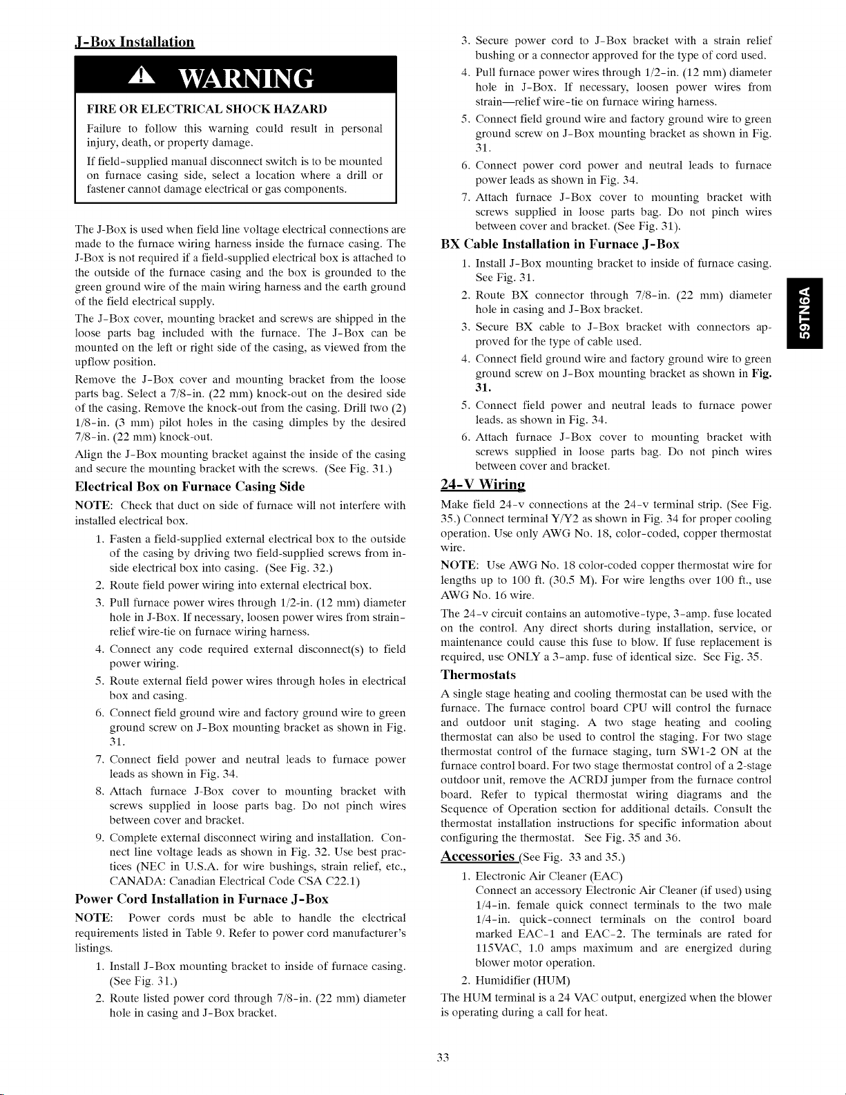
J-Box Installation
FIRE OR ELECTRICAL SHOCK HAZARD
Failure to follow this warning could result in personal
iniury, death, or property damage.
If field-supplied manual disconnect switch is to be mounted
on furnace casing side, select a location where a drill or
fastener cannot damage electrical or gas components.
The J-Box is used when field line voltage electrical connections are
made to the furnace wiring harness inside the furnace casing. The
J-Box is not required if a field-supplied electrical box is attached to
the outside of the furnace casing and the box is grounded to the
green ground wire of the main wiring harness and the earth ground
of the field electrical supply.
The J-Box cover, mounting bracket and screws are shipped in the
loose parts bag included with the furnace. The J-Box can be
mounted on the left or right side of the casing, as viewed from the
upflow position.
Remove the J-Box cover and mounting bracket from the loose
parts bag. Select a 7/8-in. (22 mm) knock-out on the desired side
of the casing. Remove the knock-out from the casing. Drill two (2)
l/8-in. (3 mm) pilot holes in the casing dimples by the desired
7/8-in. (22 mm) knock-out.
Align the J-Box mounting bracket against the inside of the casing
and secure the mounting bracket with the screws. (See Fig. 31.)
Electrical Box on Furnace Casing Side
NOTE: Check that duct on side of furnace will not interfere with
installed electrical box.
1, Fasten a field-supplied external electrical box to the outside
of the casing by driving two field-supplied screws from in-
side electrical box into casing. (See Fig. 32,)
2. Route field power wiring into external electrical box.
3, Pull furnace power wires through l/2-in, (12 mm) diameter
hole in J-Box. If necessary, loosen power wires from strain-
relief wire-tie on furnace wiring harness.
4, Connect any code required external disconnect(s) to field
power wiring.
5, Route external field power wires through holes in electrical
box and casing.
6, Connect field ground wire and factory ground wire to green
ground screw on J-Box mounting bracket as shown in Fig.
31.
7, Connect field power and neutral leads to furnace power
leads as shown in Fig. 34,
8, Attach furnace J-Box cover to mounting bracket with
screws supplied in loose parts bag. Do not pinch wires
between cover and bracket.
9, Complete external disconnect wiring and installation. Con-
nect line voltage leads as shown in Fig. 32. Use best prac-
tices (NEC in U.S.A. for wire bushings, strain relief, etc,,
CANADA: Canadian Electrical Code CSA C22,1)
Power Cord Installation in Furnace J-Box
NOTE: Power cords must be able to handle the electrical
requirements listed in Table 9, Refer to power cord manufacturer's
listings.
1, Install J-Box mounting bracket to inside of furnace casing.
(See Fig. 31 .)
2, Route listed power cord through 7/8-in, (22 mm) diameter
hole in casing and J-Box bracket.
3, Secure power cord to J-Box bracket with a strain relief
bushing or a connector approved for the type of cord used.
4. Pull furnace power wires through l/2-in. (12 mm) diameter
hole in J-Box. If necessary, loosen power wires from
strain--relief wire-tie on furnace wiring harness.
5. Connect field ground wire and factory ground wire to green
ground screw on J-Box mounting bracket as shown in Fig.
31.
6. Connect power cord power and neutral leads to furnace
power leads as shown in Fig. 34.
7. Attach furnace J-Box cover to mounting bracket with
screws supplied in loose parts bag. Do not pinch wires
between cover and bracket. (See Fig. 31).
BX Cable Installation in Furnace J-Box
1. Install J-Box mounting bracket to inside of furnace casing.
See Fig. 31.
2. Route BX connector through 7/8-in. (22 mm) diameter
hole in casing and J-Box bracket.
3. Secure BX cable to J-Box bracket with connectors ap-
proved for the type of cable used.
4. Connect field ground wire and factory ground wire to green
ground screw on J-Box mounting bracket as shown in Fig.
31.
5. Connect field power and neutral leads to furnace power
leads, as shown in Fig. 34.
6. Attach furnace J-Box cover to mounting bracket with
screws supplied in loose parts bag. Do not pinch wires
between cover and bracket.
24-V Wiring
Make field 24-v connections at the 24-v terminal strip. (See Fig.
35.) Connect terminal Y/Y2 as shown in Fig. 34 for proper cooling
operation. Use only AWG No. 18, color-coded, copper thermostat
wire.
NOTE: Use AWG No. 18 color-coded copper thermostat wire for
lengths up to 100 ft. (30.5 M). For wire lengths over 100 ft., use
AWG No. 16 wire.
The 24-v circuit contains an atttomotive-type, 3-amp. fuse located
on the control. Any direct shorts during installation, service, or
maintenance could cause this fuse to blow. If fuse replacement is
required, use ONLY a 3-amp. fuse of identical size. See Fig. 35.
Thermostats
A single stage heating and cooling thermostat can be used with the
furnace. The furnace control board CPU will control the furnace
and outdoor unit staging. A two stage heating and cooling
thermostat can also be used to control the staging. For two stage
thermostat control of the furnace staging, turn SWI-2 ON at the
furnace control board, For two stage thermostat control of a 2-stage
outdoor unit, remove the ACRDJ jumper from the furnace control
board. Refer to typical thermostat wiring diagrams and the
Sequence of Operation section for additional details, Consult the
thermostat installation instructions for specific information about
configuring the thermostat, See Fig. 35 and 36,
Accessories .(See Fig. 33 and 350
1, Electronic Air Cleaner (EAC)
Connect an accessory Electronic Air Cleaner (if used) using
l/4-in, female quick connect terminals to the two male
l/4-in, quick-connect terminals on the control board
marked EAC-I and EAC-2. The terminals are rated for
II5VAC, 1,0 amps maximum and are energized during
blower motor operation,
2, Humidifier (HUM)
The HUM terminal is a 24 VAC output, energized when the blower
is operating during a call for heat,
ii
33
Page 34
ii
Connect an accessory 24 VAC, 0.5 amp. maximum humidifier (if
used) to the ¼-in. male quick-connect HUM terminal and
COM-24V screw terminal on the control board thermostat strip.
NOTE: If the humidifier has its own 24 VAC power supply, an
isolation relay may be required. Connect the 24 VAC coil of the
isolation relay to the HUM and COM/24V screw terminal on the
control board thermostat strip. (See Fig. 33.)
3. Communication Connector (communication connection)
This connection is used when the furnace is controlled by
an optional communicating User Interface instead of a
standard thermostat. The communication plug is supplied
with the User Interface. Refer to the instructions supplied
with the User Interface for complete details. See Fig. 35.
4. Outside Air Thermistor (OAT)
The OAT connection is used in coniunction with commu-
nicating User Interface. It is not required when the furnace
is controlled by a standard type thermostat. Refer to the in-
structions supplied with the User Interface for complete de-
tails.
Alternate Power Supplies
This furnace is designed to operate on utility generated power
which has a smooth sinusoidal waveform. If the furnace is to be
operated on a generator or other alternate power supply, the
alternate power supply must produce a smooth sinusoidal
waveform for compatibility with the furnace electronics. The
alternate power supply must generate the same voltage, phase, and
frequency (Hz) as shown in Table 9 or the furnace rating plate.
Power from an alternate power supply that is non-sinusoidal may
damage the furnace electronics or cause erratic operation.
Contact the alternate power supply manufacturer for specifications
and details.
34
Page 35
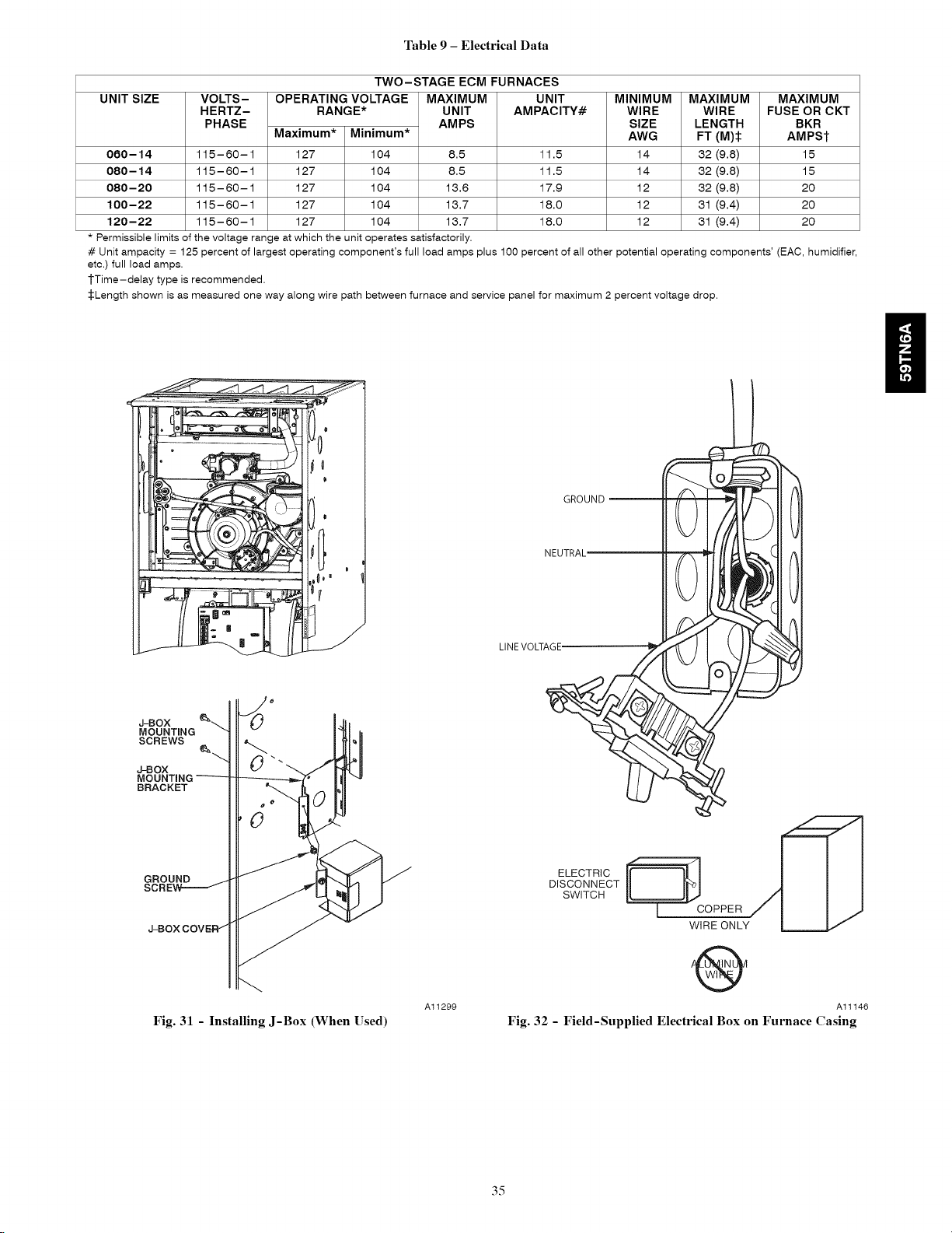
Table9- Electrical Data
TWO-STAGE ECM FURNACES
UNIT SIZE VOLTS-
HERTZ-
PHASE
080-14 115-60-1 127 104 8.5
080-14 115-60-1 127 104 8.5
080-20 115-60-1 127 104 13.6
100-22 115-60-1 127 104 13.7
120-22 115-60-1 127 104 13.7
*Permissiblelimitsofthevoltagerangeatwhichtheunitoperatessatisfactorily.
# Unit ampacity = 125 percent of largest operating component's full load amps plus 100 percent of all other potential operating components' (EAC, humidifier,
etc.) full load amps.
1"Time-delay type is recommended.
:[:Length shown is as measured one way along wire path between furnace and service panel for maximum 2 percent voltage drop.
OPERATING VOLTAGE
RANGE*
Maximum* Minimum*
MAXIMUM
UNIT
AMPS
UNIT
AMPACITY#
11.5
11.5
17.9
18.0
18.0
MINIMUM
WIRE
SIZE
AWG
14
14
12
12
12
MAXIMUM
WIRE
LENGTH
FT (M):I:
32 (9.8)
32 (9.8)
32 (9.8)
31 (9.4)
31 (9.4)
MAXIMUM
FUSE OR CKT
BKR
AMPSI"
15
15
2O
2O
2O
ii
Jq3OX _
MOUNTING
SCREWS _"--.
J-BOX
MOUNTING
BRACKET
GROUND
LINEVOLTAGE
GROUND_
NEUTRAL'
ELECTRIC
DISCONNECT
SWITCH
Fig. 31 - Installing J-Box (When Used)
A11299
O
Al1146
Fig. 32 - Field-Supplied Electrical Box on Furnace Casing
35
Page 36

H
I TO Hum_dilier Leads
I To Hum_dff_e r Leads
Fig. 33 - Field-supplied Isolation Relay for Humidifiers with Internal Power Supply
NOTE 2
-_ To HUMTerminal On I
Furnace Conirol Board
.... FIELD 24-VOLT WIRING
.... FIELD 115-, 208/230-, 460-VOLT WIRING
-- FACTORY 24-VOLT WIRING
FACTORY 115-VOLT WIRING
I
I
208/230- OR
460-VOLT
Al1157
TERMINAL
BLOCK
FURNACE
Fig. 34 - Typical Two-Stage Field Wiring Diagram
NOTES: 1. Connect Y/Y2-terminal as shown for proper operation.
2. Some thermostats require a "C" terminal connection as shown.
3. If any ofthe original wire, as supplied, must be replaced, use
same type or equivalent wire.
CONDENSING
UNIT
A11401
36
Page 37
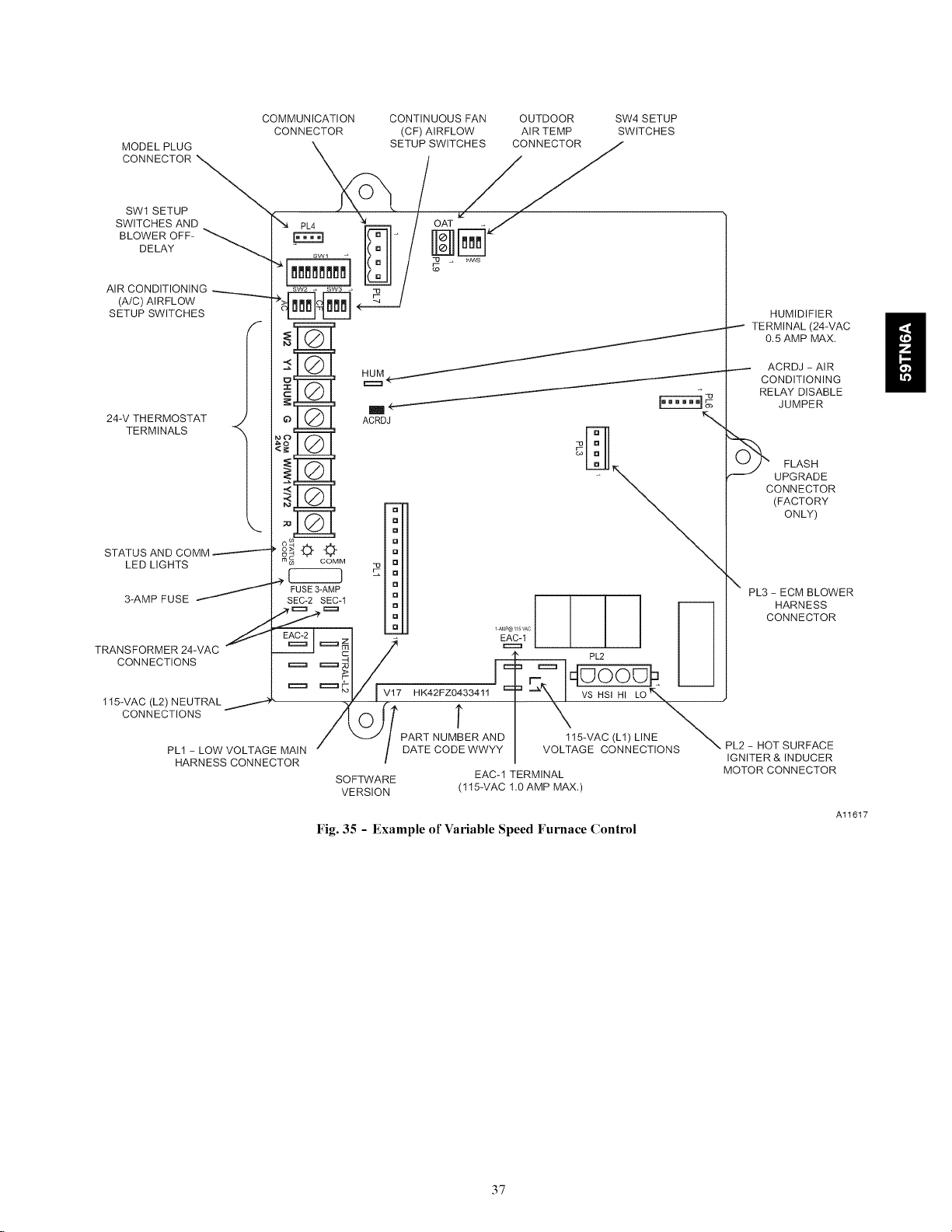
MODEL PLUG
CONNECTOR _
SWI SETUP
SWITCHES AND
BLOWER OFF- _DELAY
AIR CONDITIONING
(A/C) AIRFLOW
SETUP SWITCHES
COMMUNICATION
CONNECTOR
f
\
CONTINUOUS FAN
(CF) AIRFLOW
SETUP SWITCHES
OUTDOOR SW4 SETUP
AIR TEMP SWITCHES
HUMIDIFIER
_-_ TERMINAL (24WAC
0.5 AMP MAX.
24-V THERMOSTAT
TERMINALS <
STATUS AND COMM
LED LIGHTS
FUSE3-AMP
3-AMP FUSE _ SEC-2 SEC-1 _D I I I I
ACRDJ
m
[]
[]
[]
[]
[]
n
" z "T E_Cq
TRANSFORMER_4_VAC'_"E_I=_--' = __L_ I I
CONNECTIONS
/ I I
====F_I_ 1 ,--. Iq_oo_ I I
115-VAC (L2) NEUTRAL _,---4 _Z m . . 'k
_V Iv17HK42FZ0433411 == -_'X&I VS.S,HI LO_%
c /,oil T \ \\
PLH_ARNLOWsVcOoLTNAGcETMoAR_N/ "---1/ PA_TNUMB_ANyD VOL_I_VACo(L_L;NT_oNS\
SOFTWARE EAC-I TERMINAL
VERSION (115-VAC 1.0 AMP MAX.)
Fig. 35 - Example of Variable Speed Furnace Control
ACRDJ - AIR
CONDITIONING
RELAY DISABLE
JUMPER
O_ FLASH
UPGRADE
CONNECTOR
(FACTORY
ONLY)
\
PL3-ECM BLOWER
HARNESS
CONNECTOR
PL2-HOTSURFACE
IGNITER&INDUCER
MOTOR CONNECTOR
H
Al1617
37
Page 38
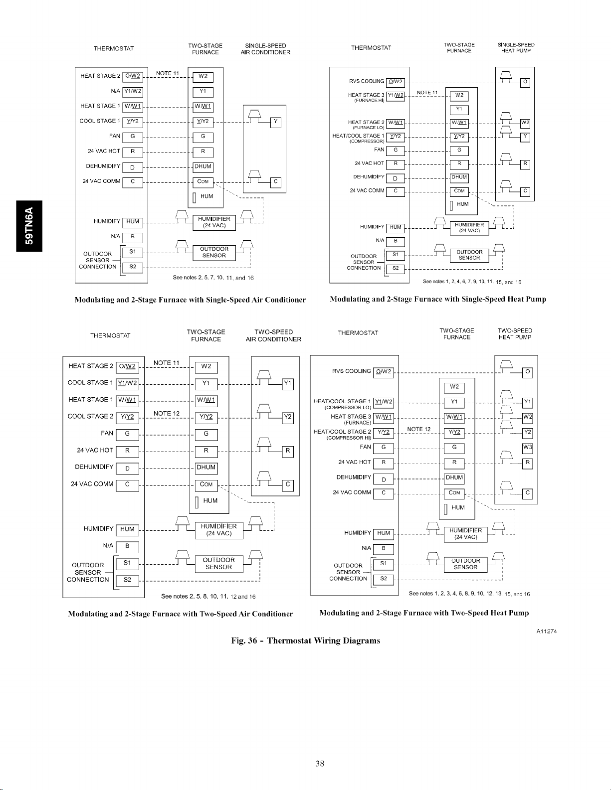
THERMOSTAT TWO-STAGE SINGLE-SPEED THERMOSTAT
FURNACE AIR CONDITIONER FURNACE HEAT PUMP
TWO-STAGE SINGLE-SPEED
HEAT STAGE 2 __
N/Ar_
HEAT STAGE 1 __
COOL STAGE 1 __
FAN __
24 VAC HOT _ _
DEHUMIDIFY __
24 VAC COMM __
HUMIDIFY __
N/A I_
OUTDOOR [[_!_- ........ _/ OUTDOOR L_,
SENSOR _ / SENSOR _' ',
CONNECT,ONLl_q ............................ :
Modulating and 2-Stage Furnace with Single-Speed Air Conditioner
THERMOSTAT
HEAT STAGE 2 __
COOL STAGE 1 I__
HEAT STAGE 1 __
COOL STAGE 2 __
FAN __
24 VAC HOT __
DEHUMIDIFY [___
24 VAC COMM __
HUMIDIFY I_1_ _
N/A I_
%_E_&%OR_-I_ -
--N-°--T!JI--
C!3
.........._ ........._-D
.........._:: ......._[3
I HUM "''"
....... _t HUMIDIFIER(24VAC) ___i
See notes 2, 5, 7, 10, 11, and 16
TWO-STAGE TWO-SPEED
FURNACE AIR CONDITIONER
NOTE 11
NOTE 12
........ HUMIDIFIER ____
........ _ OUTDOORsENSOR
-F_q
-I_q
-I_q
I HUM
(24 VAC)
,,
CONNECT,ONLIZS-
See notes 2, 5, 8, 10, 11, 12 and 16
Modulating and 2-Stage Furnace with Two-Speed Air Conditioner
Fig. 36 - Thermostat Wiring Diagrams
RVS COOLING
HEAT STAGE 3 r_
(FURNACE HI)
NOTE 11
-E_
F_q
HEAT STAGE 2
(FURNACE LO)
HEAT/COOL STAGE 1
(COMPRESSOR)
FAN __
24 VAC HOT
DEHUMIDIFY
24 VAC COMM
HUMIDIFY
N/A I_
- 1_]- .......
- [_c_- .....
...... .VAC,
......_]
HUM "'" .....
HUMIDIFIER _'
......
CON"EOT'ONLIZ5
See notes 1, 2, 4, 6, 7, 9, 10,11, 15, and 16
Modulating and 2-Stage Furnace with Single-Speed Heat Pump
THERMOSTAT TWO-STAGE TWO-SPEED
RVS COOLING
HEAT/COOL STAGE 1
(COMPRESSOR LO) r_
HEAT STAGE 3 I_
(FURNACE)
HEAT/COOL STAGE 2
(COMPRESSOR HI)
FAN
24 VAC HOT
DEHUMIDIFY
24 VAC COMM
i
HUMIDIFY [_
N/A [_
OUTDOOR [ -_1- ....... 6_J OUTDOOR l_
SENSOR--q-- [ SENSOR I..... ;
............_ ...... RLD
.... (24 VAC)
CONNECT,ONLI_ -- I
See notes 1,2,3,4,6,8,9, 10, 12, 13, 15, and16
Modulating and 2-Stage Furnace with Two-Speed Heat Pump
FURNACE HEAT PUMP
__ -_-D
F_q
....... IZ!D::-....
I HUM """ ......... s
-- i
_q HUMIDIFIER t_L
Al1274
38
Page 39

NOTES FOR THERMOSTAT WIRING DIAGRAMS
1. Heat pump MUST have a high pressure switch for dual fuel applications.
2. Refer to outdoor equipment Installation Instructions for additional information and setup procedure.
3. If the heat pump date code is 1501E or earlier, select the "ZONE" position on the two speed heat pump control. Heat pumps with date
code 1601E and later do not have or require a "ZONE" selection.
4. Outdoor Air Temperature Sensor must be attached in all dual fuel applications.
5. Configure the thermostat for air conditioner installations. Refer to thermostat instructions.
6. Configure thermostat for heat pump installations. Refer to thermostat instructions.
7. Configure thermostat for single-stage compressor operation. Refer to thermostat instructions.
8. Configure thermostat for two-stage compressor operation. Refer to thermostat instructions.
9. Configuration thermostat for Dual Fuel Operation. Refer to thermostat instructions.
10. NO connection should be made to the furnace HUM terminal when using a thermostat with a 24 volt humidifier output.
11. Optional connection - If wire is connected to W2 on furnace control board, either dip switch SWI-2 or SWI-LHT on furnace control
should be set in ON position to allow thermostat to control furnace staging.
12. Optional connection - If wire is connected, ACRDJ jumper on furnace control should be removed to allow thermostat to control
outdoor unit staging.
13. Furnace must control its own staging operation via furnace control algorithm. This is factory default.
14. The RVS Sensing terminal "L" should not be connected. This is used internally to sense defrost operation.
15. If thermostat has internal control of heat pump balance point, DO NOT SELECT the "FURNACE INTERFACE" or "BALANCE
POINT" option on the two-speed heat pump control board. Refer to thermostat instructions
16. Configure Dehumidify function to remove 24 VAC from Dehum terminal on a demand to dehumidify.
ii
39
Page 40
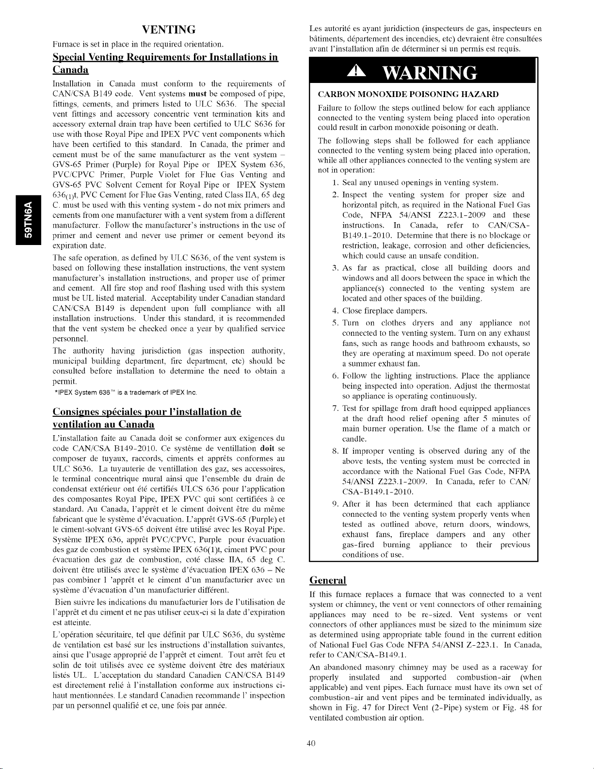
ii
VENTING
Furnace is set in place in the required orientation.
Special Venting Requirements for Installations in
Canada
Installation in Canada must conform to the requirements of
CAN/CSA B149 code. Vent systems must be composed of pipe,
fittings, cements, and primers listed to ULC $636. The special
vent fittings and accessot T concentric vent termination kits and
accessot T external drain trap have been certified to ULC $636 for
use with those Royal Pipe and IPEX PVC vent components which
have been certified to this standard. In Canada, the primer and
cement must be of the same manufacturer as the vent system
GVS-65 Primer (Pm_le) for Royal Pipe or IPEX System 636,
PVC/CPVC Primer, Pm_le Violet for Flue Gas Venting and
GVS-65 PVC Solvent Cement for Royal Pipe or IPEX System
636(1)t, PVC Cement for Flue Gas Venting, rated Class IIA, 65 deg
C. must be used with this venting system - do not mix primers and
cements from one manufacturer with a vent system from a different
manufacturer. Follow the manufacturer's instructions in the use of
primer and cement and never use primer or cement beyond its
expiration date.
The safe operation, as defined by ULC $636, of the vent system is
based on following these installation instructions, the vent system
manufacturer's installation instructions, and proper use of primer
and cement. All fire stop and roof flashing used with this system
must be UL listed material. Acceptability under Canadian standard
CAN/CSA B149 is dependent upon full compliance with all
installation instructions. Under this standard, it is recommended
that the vent system be checked once a year by qualified service
personnel.
The authority having jurisdiction (gas inspection authority,
municipal building department, fire department, etc) should be
consulted before installation to determine the need to obtain a
permit.
*IPEX System 636T'_isa trademark of IPEXInc.
Consignes sp6ciales pour l'installation de
ventilation au Canada
L'installation faite au Canada doit se conformer aux exigences du
code CAN/CSA B149-2010. Ce syst_me de ventillation doit se
composer de tuyaux, raccords, ciments et appr_ts conformes au
ULC $636. La tuyauterie de ventillation des gaz, ses accessoires,
le terminal concentrique mural ainsi que l'ensemble du drain de
condensat extdrieur ont _td certifids ULCS 636 pour l'application
des composantes Royal Pipe, IPEX PVC qui sont certifides 5. ce
standard. Au Canada, l'appr_t et le ciment doivent _tre du m_me
fabricant que le syst_me d'@acuation. L'appr_t GVS-65 (Purple) et
le ciment-solvant GVS-65 doivent _tre utilis6 avec les Royal Pipe.
Syst_me IPEX 636, appr_t PVC/CPVC, Purple pour @acuation
des gaz de combustion et syst_me IPEX 636(1)t, ciment PVC pour
@acuation des gaz de combustion, cord classe IIA, 65 deg C.
doivent _tre utilis6s avec le syst_me d'@acuation IPEX 636 - Ne
pas combiner 1 'appr_t et le ciment d'un manufacturier avec un
syst_me d'@acuation d'un manufacturier different.
Bien suivre les indications du manufacturier lors de l'utilisation de
l'apprat et du ciment et ne pas utiliser ceux-ci si la date d'expiration
est atteinte.
L'opdration sdcuritaire, tel que ddfinit par ULC $636, du systame
de ventilation est basd sur les instructions d'installation suivantes,
ainsi que l'usage approprid de l'apprat et ciment. Tout arrat feu et
solin de toit utilisds avec ce systame doivent atre des matdriaux
listds UL. L'acceptation du standard Canadien CAN/CSA B149
est directement relid fi l'installation conforme aux instructions ci-
haut mentionndes. Le standard Canadien recommande 1' inspection
par un personnel qualifid et ce, une fois par annde.
Les autoritd es ayant juridiction (inspecteurs de gas, inspecteurs en
bfitiments, d@artement des incendies, etc) devraient _tre consultdes
avant l'installation afin de d_terminer si un permis est requis.
CARBON MONOXIDE POISONING HAZARD
Failure to follow the steps outlined below for each appliance
connected to the venting system being placed into operation
could result in carbon monoxide poisoning or death.
The following steps shall be followed for each appliance
connected to the venting system being placed into operation,
while all other appliances connected to the venting system are
not in operation:
1. Seal any unused openings in venting system.
2. Inspect the venting system for proper size and
horizontal pitch, as required in the National Fuel Gas
Code, NFPA 54/ANSI Z223.1-2009 and these
instructions. In Canada, refer to CAN/CSA-
B149.1-2010. Determine that there is no blockage or
restriction, leakage, corrosion and other defciencies,
which could cause an unsafe condition.
3. As far as practical, close all building doors and
windows and all doors between the space in which the
appliance(s) connected to the venting system are
located and other spaces of the building.
4. Close fireplace dampers.
5. Turn on clothes dryers and any appliance not
connected to the venting system. Turn on any exhaust
fans, such as range hoods and bathroom exhausts, so
they are operating at maximum speed. Do not operate
a summer exhaust fan.
6. Follow the lighting instructions. Place the appliance
being inspected into operation. Adjust the thermostat
so appliance is operating continuously.
7. Test for spillage from draft hood equipped appliances
at the draft hood relief opening after 5 minutes of
main burner operation. Use the flame of a match or
candle.
8. If improper venting is observed during any of the
above tests, the venting system must be corrected in
accordance with the National Fuel Gas Code, NFPA
54/ANSI Z223.1-2009. In Canada, refer to CAN/
CSA-BI49.1-2010.
9. After it has been determined that each appliance
connected to the venting system properly vents when
tested as outlined above, return doors, windows,
exhaust fans, fireplace dampers and any other
gas-fired burning appliance to their previous
conditions of use.
General
If this furnace replaces a furnace that was connected to a vent
system or chimney, the vent or vent connectors of other remaining
appliances may need to be re-sized. Vent systems or vent
connectors of other appliances must be sized to the minimum size
as determined using appropriate table found in the current edition
of National Fuel Gas Code NFPA 54/ANSI Z-223.1. In Canada,
refer to CAN/CSA-BI49.1.
An abandoned masonry chimney may be used as a raceway for
properly insulated and supported combustion-air (when
applicable) and vent pipes. Each furnace must have its own set of
combustion-air and vent pipes and be terminated individually, as
shown in Fig. 47 for Direct Vent (2-Pipe) system or Fig. 48 for
ventilated combustion air option.
40
Page 41

A furnaceshallnotbeconnectedto a chinmey flue serving a
separate appliance designed to burn solid fuel.
Other gas appliances with their own venting system may also use
the abandoned chinmey as a raceway providing it is permitted by
local code, the current edition of the National Fuel Gas Code and
the vent or liner manufacturer's installation instructions. Care must
be taken to prevent the exhaust gases from one appliance from
contaminating the combustion air of other gas appliances.
Do not take combustion air from inside the chinmey when using
ventilated combustion air or single pipe vent option.
These furnaces can be vented as either direct vent furnace,
ventilated combustion air system or non-direct (single pipe) vent
system. Each type of venting system is described below. Common
venting between furnaces or other appliances prohibited.
Materials
U.S.A.
Combustion air and vent pipe, fittings, primers, and solvents nmst
conform to American National Standards Institute (ANSI)
standards and American Society for Testing and Materials (ASTM)
standards. See Table 11 for approved materials for use in the
U.S.A.
Canada
Special Venting Requirements for Installations in Canada
Installation in Canada nmst conform to the requirements of
CAN/CSA B149 code. Vent systems must be composed of pipe,
fittings, cements, and primers listed to ULC $636.
Venting Systems
A factory accessory KGAVT vent termination kit nmst be used for
all direct vent terminations. Termination kits are available for 2-in.
or 3-in. pipe. See Table 10 for available options.
Table 10 - Vent Termination Kit for Direct Vent (2-pipe)
Systems
DIRECT VENT TERMINATION DIAM. OF COMBUS-
(2-PIPE) SYSTEM TION AIR AND VENT
TERMINATION KIT PIPES - IN. (mm)
2-in. (51 mm) Single Penetration of 1, 1-1/2, 2, or 2-1/2
Concentric Vent Kit Wall or Roof (24, 36, 51,64 mm)
3-in. (76 mm) Single Penetration of 2-1/2, 3 or 4
Concentric Vent Kit wall or Roof (64, 76, 102 mm)
2-in. (51 mm) 2-Pipe Termination 1, 1-1/2 or 2
Termination Bracket
Kit System (25, 36, 51 mm)
3-in. (76 mm) 2-Pipe Termination 2-1/2, 3 or 4
Termination Bracket
Kit System (64, 76, 102 mm)
Direct Vent / 2-Pipe System
In a direct-vent (2-pipe) system, all air for combustion is taken
directly from outdoor atmosphere, and all flue products are
discharged to outdoor atmosphere. Combustion-air and vent pipes
nmst terminate together in the same atmospheric pressure zone,
either through the roof or a sidewall (roof termination preferred). A
factory accessory vent termination kit MUST be used in a direct
vent (2-pipe) system. See Fig. 45 for required clearances.
Ventilated Combustion Air Systems
In a ventilated combustion air option, the vent terminates and
discharges the flue products directly to the outdoors similar to a
direct vent system. See Fig. 46 for required clearances.
All air for combustion is piped directly to the furnace from a space
that is well ventilated with outdoor air (such as an attic or crawl
space) and the space is well isolated from the living space or
garage. Combustion air requirements for this option are the same as
the requirements for providing outside air for combustion for a
single pipe vent system. Refer to the "Air For Combustion and
Ventilation Section.
Provisions for adequate combustion, ventilation, and dilution air
must be provided in accordance with:
U.S.A. Installations: Section 9.3 NFPA 54/ANSI Z223.1-2009,
Air for Combustion and Ventilation and applicable provisions of
the local building codes.
Canadian Installations: Part 8 of CAN/CSA-BI49.1-10. Venting
Systems and Air Supply for Appliances and all authorities having
jurisdiction.
Non-Direct Vent (1-pipe) System
In a non direct-vent (1-pipe) system, all air for combustion is taken
from the area adjacent to furnace, and all flue products are
discharged to outdoor atmosphere. Air for combustion nmst be
supplied as described in the Air For Combustion and Ventilation
Section. Do not use an abandoned chinmey to supply outside air to
the furnace. See Fig. 46 for required clearances.
Provisions for adequate combustion, ventilation, and dilution air
must be provided in accordance with:
U.S.A. Installations: Section 9.3 NFPA 54/ANSI Z223.1-2009, Air
for Combustion and Ventilation and applicable provisions of the
local building codes.
Canadian Installations: Part 8 of CAN/CSA-B149.1-10. Venting
Systems and Air Supply for Appliances and all authorities having
jurisdiction.
A combustion air pipe to the outdoors is not required for a single
pipe vent system. A 12-in. (304 ram) long pipe with a 2-in. (51
ram) tight radius 90 degree elbow is required to be attached to the
combustion air pipe adapter on the furnace. (See Fig. 44.)
Locating the Vent Termination
General
NOTE: Termination Requirements for the Provinces of
Alberta and Saskatchewan are located at the end of this
section.
Combustion-air (direct vent/2-pipe system only) and vent pipe
must terminate outside structure, either through sidewall or roof.
For vent termination clearance, refer to Fig. 45 for Direct
Vent/2-Pipe system and Fig. 46 for Non-direct Vent/I-Pipe
system. For exterior termination arrangements, refer to Fig. 47 for
Direct Vent/2-Pipe system and Fig. 48 for Non- Direct/l-Pipe
system.
Roof termination is preferred since it is less susceptible to damage
or contamination, and it has less visible vent vapors. Sidewall
terminations require sealing or shielding of building surfaces with a
corrosive resistance material due to corrosive combustion products
of vent system.
NOTE: (Direct Vent/2-Pipe system ONLY) A factory accessory
termination kit MUST be used. See Table 10 for available options.
When determining appropriate location for termination, consider
the following guidelines:
1. Comply with all clearance requirements stated in Fig. 45 or
Fig. 46 per application.
2. Termination or termination kit should be positioned where
vent vapors will not damage plants/shrubs or air condi-
tioning equipment.
3. Termination or termination kit should be positioned so that
it will not be affected by wind eddy, such as inside building
corners, nor by recirculation of flue gases, airborne leaves,
or light snow.
4. Termination or termination kit should be positioned where it
will not be damaged by or subjected to foreign objects such
as stones, balls, etc.
5. Termination or termination kit should be positioned where
vent vapors are not objectionable.
Direct Vent / 2-Pipe System
Direct vent (2-pipe) vent and combustion air pipes must terminate
outside the structure. Follow all clearances as shown Fig. 45.
41
Page 42

ii
Allowable vent and combustion air terminations are shown in Fig.
47.
Ventilated Combustion Air
The vent pipe for a Ventilated Combustion Air System must
terminate outdoors. Follow all vent termination clearances shown
in Fig. 46. Allowable vent terminations are shown in Fig. 48. The
combustion air pipe terminates in a well-ventilated attic or crawl
space. Follow the clearances as shown in Fig. 50.
The combustion air pipe cannot terminate in attics or crawl spaces
that use ventilation fans designed to operate in the heating season.
If ventilation fans are present in these areas, the combustion air
pipe must terminate outdoors as a Direct Vent System.
Non-Direct Vent / 1-Pipe System
The vent pipe for a Non Direct Vent (I-pipe) system must
terminate outdoors. Follow all vent termination clearances shown
in Fig. 46. Allowable vent terminations are shown in Fig. 48
A combustion air pipe to the outdoors is not required for a
Non-Direct Vent System. A 12-in. long section of pipe with a
tight radius 2-in. (50.8 ram) 90 degree elbow is required to be
attached to the furnace.
Termination Requirements for the Provinces of Alberta and
Saskatchewan
The Provinces of Alberta and Saskatchewan require a minimum
unobstructed distance of 4 ft. (1.2 M) from the foundation to the
property line of the adjacent lot for vent termination of any
appliance with an input over 35,000 btuh. If there is less than 4 ft.
(1.2 M) of unobstructed distance to the property line of the
adjacent lot, no type of vent termination is permitted for appliances
with inputs greater than 35,000 btuh.
There are no additional restrictions on unobstructed distances
greater than 8 ft. (2.4 M). All single, two-pipe and concentric vents
nmy be used, providing all other Code and manufacturer's
requirements in these instructions are adhered to. Refer to the
appropriate Vent Termination section above for locating the vent
termination
If the unobstructed distance from the foundation to the property
line of the adjacent lot is no less than 4 ft. (1.2 M) and no greater
than 8 ft. (2.4 M), it will be necessary to re-direct the flue gas
plume. In this situation, a concentric vent kit cannot be used. A
2-pipe termination (or single pipe termination when permitted) that
re-directs the flue gas away by use of an elbow or tee, certified to
ULC $636 from the adjacent property line must be used. See Fig.
49.
The concentric vent kit currently cannot be modified to attach an
elbow to the vent portion of the rain cap. A tee attached to the rain
cap could potentially direct the flue gas plume toward the intake air
stream and contaminate the incoming combustion air for the
furnace.
Refer to Fig. 49 for terminations approved for use in Alberta and
Saskatchewan,
Size the Vent and Combustion Air Pipes
General
Furnace combustion air and vent pipe connections are sized for
2-in. (51 ram) pipe. Any pipe diameter change should be made
outside furnace casing in vertical pipe. Any change in diameter to
the pipe must be made as close to the furnace as reasonably
possible.
The Maximum Vent Length for the vent and combustion air pipe
(when used) is determined from the Maxinmm Equivalent Vent
Length in Table 13 or 15, minus the number of fittings nmltiplied
by the deduction for each type of fitting used from Table 14.
The measured length of pipe used in a single or 2-pipe termination
is included in the total vent length. Include a deduction for a Tee
when used for Alberta and Saskatchewan terminations. Concentric
vent terminations, pipe lengths or elbows do not require a
deduction from the Maxinmm Equivalent Vent Length.
1. Measure the individual distance from the furnace to the ter-
mination for each pipe.
2. Select a Maximum Equivalent Vent Length (MEVL) longer
than the measured distance of the individual vent and com-
bustion air connections to the vent termination.
3. Count the number of elbows for each pipe.
4. For each pipe, multiply the number of elbows by the equi-
valent length for the type of elbow used. Record the equi-
valent length of all the elbows for each pipe.
5. If a Tee is used on the termination (Alberta and Saskat-
chewan, when required) record the equivalent length of the
Tee used.
6. Calculate each individual Maximum Vent Length by sub-
tracting the equivalent lengths of the fittings of the individu-
al vent and combustion air pipes from the Maximum Equi-
valent Vent Length shown in Table 13 and 15.
7. If the Maximum Vent Length calculated is longer than the
individual measured length of the vent pipe and combustion
air pipe, then the diameter of pipe selected may be used.
8. If the Maximum Vent Length calculated is shorter than the
individual measured length of either the vent pipe or the
combustion air pipe, recalculate the Maximum Vent Length
using the next larger diameter pipe.
NOTE: If the calculated Maximum Vent Lengths results in
different diameter pipes for the vent and combustion air, select the
larger diameter for both pipes.
NOTE: If the Maximum Vent Length for diameter of the pipe
selected is longer than the measured length and the equivalent
length of all the fittings and terminations, recalculate using the next
smaller diameter. If the recalculated Maximum Vent Length is
longer than the measured length of the vent pipe and combustion
air pipe, then that diameter of pipe selected may be used.
When installing vent systems pipe lengths of 10 ft. (3.0 M) or less,
use the smallest allowable pipe diameter. Do not use pipe size
greater than required or incomplete combustion, flame disturbance,
or flame sense lockout may occur.
For vent systems longer than 10 ft. (3.0 M), any larger diameter
show in Table 13 or 15 may be used.
Combustion Air and Vent Piping Insulation
Guidelines
NOTE: Use closed cell, neoprene insulation or equivalent.
The vent pipe may pass through unconditioned areas. The amount
of exposed pipe allowed is shown in Table 12.
1. Using winter design temperature (used in load calculations),
find appropriate temperature for your application and fur-
nace model.
2. Determine the amount of total and exposed vent pipe.
3. Determine required insulation thickness for exposed pipe
length(s).
4. When combustion air inlet piping is installed above a sus-
pended ceiling, the pipe MUST be insulated with moisture
resistant insulation such as Armaflex or other equivalent
type of insulation.
5. Insulate combustion air inlet piping when run in warm, hu-
mid spaces.
6. Install the insulation per the insulation manufacturer's in-
stallation instructions.
42
Page 43

NOTE: Pipe length (ft. / M) specified for maximum pipe lengths
located in unconditioned spaces cannot exceed total allowable pipe
length as calculated from Table 13 or 15.
Configure the Furnace
CARBON MONOXIDE POISONING HAZARD
Failure to follow this warning could result in personal
iniury or death.
To route the vent pipe and combustion air pipe through the
furnace, the manufacturer supplied kit must be used. Failure
to properly seal the blower compartment from the furnace
vestibule could result in the circulation of carbon monoxide
throughout the structure. The vent pipe and combustion air
pipe must be a continuous pipe while passing through the
blower compartment. Seals supplied in this kit must be
installed per the instructions provided. Follow all
procedures outlined in these instructions.
Install the Vent and Combustion Air Pipe
With the furnace installed in the required position, remove the
desired knockouts from the casing. It will be necessary to remove
one knockout for the vent pipe and the other knockout for the
combustion air connection. (See Fig. 12.)
Use a fiat blade screwdriver and tap on the knockout on opposite
sides, where the knockout meets the casing. Fold the knockout
down with duct pliers and work the knockout back and forth until
it is removed. Trim any excess metal from the knockout with tin
snips.
The vent elbow can be rotated to the required location on the
casing if necessary. See Fig. 38. To rotate the vent elbow:
1. Loosen the clamp on the inlet of the vent elbow attached to
the inducer.
2. Rotate the vent elbow to the required position. There are
rounded notches in the vent elbow to align it with the
inducer housing for each orientation.
3. Tighten the clamp around the vent elbow. Torque the clamp
to 15 lb-in. See Fig, 39-42.
Installing the Vent Pipe Adapter and Combustion Air
Pipe Adapter
CARBON MONOXIDE POISONING HAZARD
Failure to follow this warning could result in personal
iniury or death.
To route the vent pipe and combustion air pipe through the
furnace, the manufacturer supplied kit must be used. Failure
to properly seal the blower compartment from the furnace
vestibule could result in the circulation of carbon monoxide
throughout the structure. The vent pipe and combustion air
pipe must be a continuous pipe while passing through the
blower compartment. Seals supplied in this kit must be
installed per the instructions provided. Follow all
procedures outlined in these instructions.
NOTE: The rubber coupling that attaches to the vent pipe adapter
must be used. The adapter seals the vent pipe to the casing and
reduces the strain on the vent elbow attached to the inducer.
1, Apply the gaskets to the vent pipe and combustion air pipe
adapters, See Fig. 3%
NOTE: The vent pipe adapter has a larger ID than the combustion
air pipe adapter.
2. Align the screw holes in the plastic vent pipe adapter with
the dimples in the casing.
3. Pilot drill the screw holes for the adapter in the casing and
attach the vent pipe adapter to the furnace with sheet metal
screws
4. Slide the end of the rubber vent coupling with notches in it
over the standoffs on the vent pipe adapter.
5. Insert a length of vent pipe through the coupling into the
outlet of the vent elbow.
6. Tighten the clamp around the outlet of the vent elbow.
Torque the clamp to 15 lb-in.
Install the remaining vent and combustion air pipes as shown
below. It is recommended that all pipes be cut, prepared, and
preassembled before pem_anently cementing any joint.
1. Working from furnace to outside, cut pipe to required
length(s).
2. Deburr inside and outside of pipe.
3. Chamfer outside edge of pipe for better distribution of
primer and cement.
4. Clean and dry all surfaces to be joined.
5. Check dry fit of pipe and mark insertion depth on pipe.
6. Insert the vent pipe into the vent elbow.
7. Torque clamp on vent elbow 15 lb-in.
8. Torque clamp on vent coupling 15 lb-in.
9. Insert the combustion air pipe into the adapter.
10. Pilot drill a screw hole through the adapter into the combus-
tion air pipe and secure the pipe to the adapter with sheet
metal screws.
11. Seal around the combustion air pipe with silicone or foil
tape.
12. After pipes have been cut and preassembled, apply generous
layer of cement primer to pipe fitting socket and end of pipe
to insertion mark. Quickly apply approved cement to end of
pipe and fitting socket (over primer). Apply cement in a
light, uniform coat on inside of socket to prevent buildup of
excess cement. Apply second coat.
13. While cement is still wet, twist pipe into socket with 1/4-in.
turn. Be sure pipe is fully inserted into fitting socket.
14. Wipe excess cement from joint. A continuous bead of ce-
ment will be visible around perimeter of a properly made
joint.
15. Handle pipe joints carefully until cement sets.
16. Horizontal portions of the venting system shall be suppor-
ted to prevent sagging. Support combustion air piping and
vent piping a minimum of every 5 ft. (1.5M)[3 ft. (.91M)
for SDR-21 or -26 PVC] using perforated metal hanging
strap or commercially available hangars designed to support
plastic pipe.
17. Prevent condensate from accumulating in the pipes by slop-
ing the combustion air piping and vent piping downward
towards furnace a minimum of l/4-in, per linear ft. with no
sags between hangers.
18. Complete the vent and combustion air pipe installation by
connecting the concentric vent or by installing the required
termination elbows as shown in Fig. 47, 48 and 49.
For Ventilated Combustion Air Termination, See Fig. 50
19. Use appropriate methods to seal openings where combus-
tion air pipe and vent pipe pass through roof or sidewall.
Optional Installation of the vent pipe
This option provides a disconnect point for the vent pipe. The vent
pipe must be cemented to the plastic vent pipe adapter to maintain
a sealed vestibule. See Fig. 43.
1. Insert a length of vent pipe through the casing into the
outlet of the vent elbow.
43
ii
Page 44
2. Slide the plastic vent pipe adapter over the length of the
vent pipe down to the furnace casing. Mark the pipe where
it is flush with the outlet of the adapter.
3. Remove the pipe from the furnace and the adapter and cut
off any excess pipe.
4. Clean and prime the end of the pipe that is flush with the
vent adapter with a primer that is appropriate for the type of
pipe being used.
5. Re-insert the pipe through the casing into the vent elbow.
6. Tighten the clamp around the outlet of the vent elbow.
Torque the clamp to 15 lb-in.
7. Apply cement to the end of the pipe and to the inside of the
plastic vent adapter.
8. Slide the adapter over the vent pipe and align the screw
holes in the adapter with the dimples in the furnace casing.
9. Pilot drill 1/8-in. screw holes for the adapter in the casing
and secure the adapter to the furnace with sheet metal
screws.
10. Loosen the clamps on the rubber vent coupling.
11. Slide the end of the coupling with notches in it over the
standoffs in the vent pipe adapter.
12. Tighten the clamp of the coupling over the vent pipe
adapter. Torque the lower clamp around the vent pipe
adapter to 15 lb-in.
13. Pilot drill a 1/8-in. hole in the combustion air pipe adapter.
14. Complete the vent and combustion air pipe as shown in
"Install the Vent and Combustion Air Pipe"
Installing the Vent Termination
Roof Terminations
A roof termination of any type will require a 4-in. (102 mm)
flashing for a 2 in. (51 mm) concentric vent or a 5-in. diameter
(127 mm) flashing for a 3-in. (76 mm) concentric vent kit. For
two-pipe or single pipe vent systems, a flashing for each pipe of the
required diameter will be necessary.
It is recommended that the flashing be installed by a roofer or
competent professional prior to installing the concentric vent. The
terminations can be installed on a flat or pitched roof.
Concentric Vent
Single or multiple concentric vent must be installed as shown in
Fig. 47. Maintain the required separation distance between vents
or pairs of vents as shown in Fig. 47 and all clearance shown in
Fig. 45.
Cut one 4-in. (102 mm) diameter hole for 2-in. (51 mm) kit, or
one 5-in. (127 mm) diameter hole for 3-in. (76 mm) kit in the
desired location.
Loosely assemble concentric vent/combustion air termination
components together using instructions in kit.
Slide assembled kit with rain shield REMOVED through hole in
wall or roof flashing.
NOTE: Do not allow insulation or other materials to accumulate
inside of pipe assembly when installing it through hole.
Disassemble loose pipe fittings. Clean and cement using same
procedures as used for system piping.
Two-Pipe and Single-Pipe Terminations
Single and two pipe vent must be installed as shown in Fig. 47 and
48. Maintain the required separation distance between vents or
pairs of vents as shown in Fig. 47 and 48. and all clearance shown
in Fig. 45 and 46.
Cut the required number of holes in the roof or sidewall for vent
and (when used) combustion air pipes. Sidewall holes for two-pipe
vent terminations should be side-by-side, allowing space between
the pipes for the elbows to fit on the pipes.
Holes in the roof for two pipe terminations should be spaced no
more than 18 in. (457 mm) apart.
Termination elbows will be installed after the vent and (if used)
combustion air pipe is installed.
Sidewall Terminations
Concentric Vent
Determine an appropriate location for termination kit using the
guidelines provided in section "Locating The Vent Termination" in
this instruction.
1. Cut one 4-in. diameter hole for 2-in. kit, or one 5-in. dia-
meter hole for 3-in. kit.
2. Loosely assemble concentric vent/combustion air termina-
tion components together using instructions in kit.
3. Slide assembled kit with rain shield REMOVED through
hole.
NOTE: Do not allow insulation or other materials to accumulate
inside of pipe assembly when installing it through hole.
4. Locate assembly through sidewall with rain shield posi-
tioned no more than 1-in. (25 mm) from wall as shown in
Fig. 47.
5. Disassemble loose pipe fittings. Clean and cement using
same procedures as used for system piping.
2-Pipe and 1-Pipe Vent Termination
Determine an appropriate location for termination kit using the
guidelines provided in section "Locating The Vent Termination" in
this instruction.
1. Cut 2 holes, 1 for each pipe, of appropriate size for pipe size
being used.
2. Loosely install elbow in bracket and place assembly on
combustion-air pipe.
3. Install bracket as shown in Fig. 47 and 49.
NOTE: For applications using vent pipe option indicated by
dashed lines in Fig. 47 and 48, rotate vent elbow 90 ° from
position.
4. Disassemble loose pipe fittings. Clean and cement using
same procedures as used for system piping.
(Direct Vent / 2-Pipe System ONLY)
When 2 or more furnaces are vented near each other, 2 vent
terminations may be installed as shown in Fig. 47, but next vent
termination must be at least 36 in. (914 mm) away from first 2
terminations. It is important that vent terminations be made as
shown in Fig. 47 to avoid recirculation of flue gases.
Inducer Outlet Restrictor
To improve efficiency and operation of 40,000 BTUH input
models on very short vent systems, an inducer outlet restrictor is
required to be installed on the outlet of the inducer assembly. The
outlet restrictor is shipped in the loose parts bag.
To determine if the outlet restrictor is required, see Table 13 and
Table 15. Failure to use an outlet choke when required may result
in flame disturbance or flame sense lockout.
To install the outlet restrictor:
1. Remove the vent elbow from the inducer outlet.
2. Align the lock tabs on the outlet restrictor with the slots on
inside outlet of the inducer assembly.
3. Snap the outlet restrictor in place.
4. Re-install the vent elbow.
5. Torque vent elbow clamp 15-1b-in.
44
Page 45
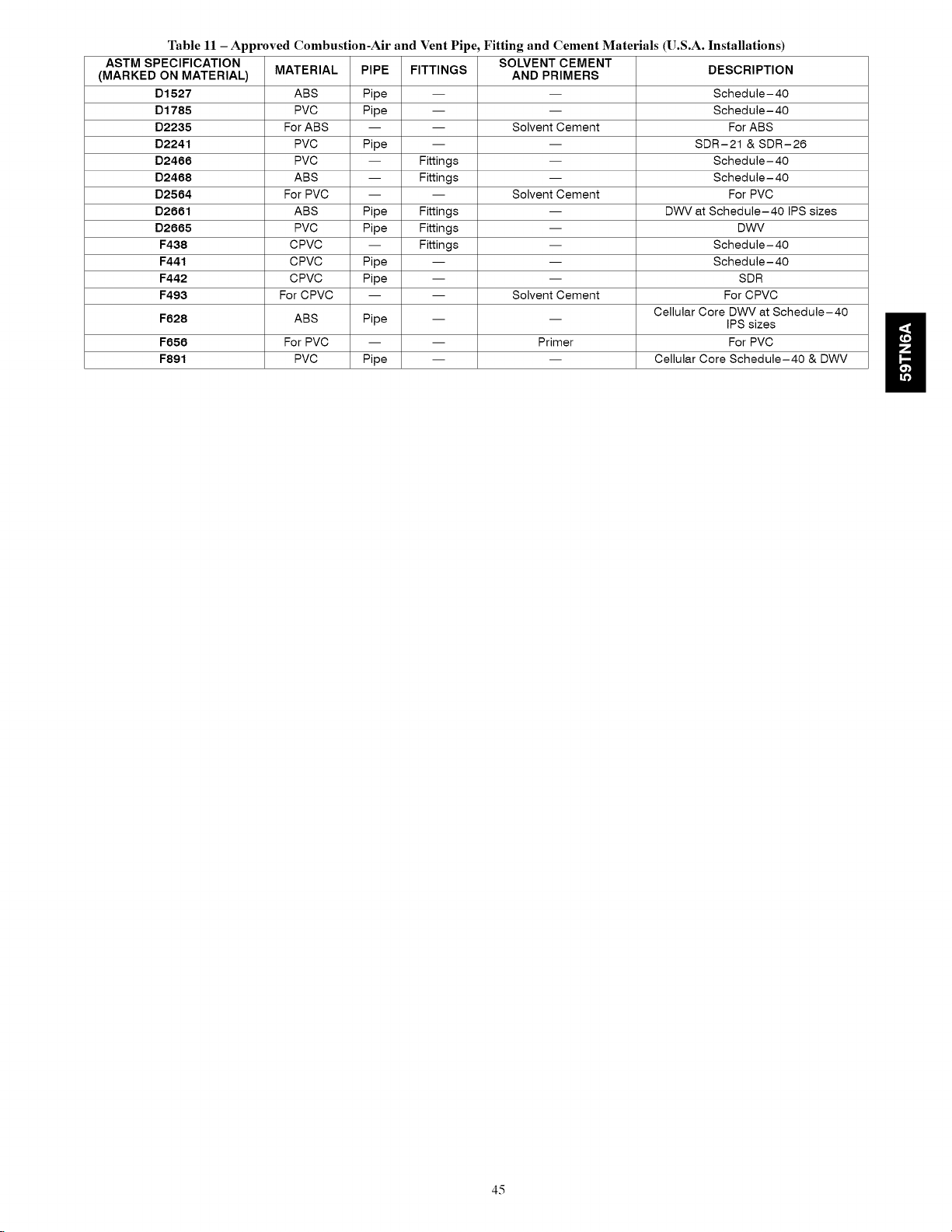
Table11 - Approved Combustion-Air and Vent Pipe, Fitting and Cement Materials (U.S.A. Installations)
ASTM SPECIFICATION SOLVENT CEMENT
(MARKED ON MATERIAL) MATERIAL PIPE FITTINGS AND PRIMERS DESCRIPTION
D1527
D1785
D2235
D2241
D2466
D2468
D2564
D2661
D2665
F438
F441
F442
F493
F628
F656
F891
ABS Pipe --
PVC Pipe --
For ABS -- --
PVC Pipe --
PVC -- Fittings
ABS -- Fittings
For PVC -- --
ABS Pipe Fittings
PVC Pipe Fittings
CPVC -- Fittings
CPVC Pipe --
CPVC Pipe --
For CPVC -- --
ABS Pipe --
For PVC -- --
PVC Pipe --
Solvent Cement
Solvent Cement
DWV at Schedule-40 IPS sizes
Solvent Cement
Cellular Core DWV at Schedule-40
Primer
Cellular Core Schedule-40 & DWV
Schedule-40
Schedule-40
For ABS
SDR-21 & SDR-26
Schedule-40
Schedule-40
For PVC
DWV
Schedule-40
Schedule-40
SDR
For CPVC
IPS sizes
For PVC
45
Page 46

Two Stage
Furnace High
Heat Input
40000*
60000
80000
Table 12 - Maximum Allowable Exposed Vent Lengths Insulation Table - Ft. / M
No Insulation 3/8-in. (9.5 mm)
Winter Design
Tempo F (oC)
20 (-10)
0 (-20)
-20 (-30)
-40 (-40)
20 (-10) M 9.1 15.5 15.5 13.7 N/A 9.1 41.1 42.1 36.6 N/A 9.1 41.1 49.4 43.0 N/A
0 (-20) M 9.1 7.3 7.0 4.9 N/A 9.1 28.3 25.0 21.0 N/A 9.1 33.8 29.9 25.3 N/A
-20 (-30) M 5.5 3.4 2.7 0.3 N/A 9.1 19.8 17.1 13.4 N/A 9.1 24.1 20.7 16.8 N/A
-40 (-40) M 3.0 0.9 0.0 0.0 N/A 9.1 14.6 12.2 8.8 N/A 9.1 18.0 15.2 11.6 N/A
20 (-10) M 6.1 19.5 19.5 17.1 14.3 6.1 21.3 52.7 45.7 38.1 6.1 21.3 53.3 53.9 44.8
0 (-20) M 6.1 9.8 9.1 6.7 3.4 6.1 21.3 31.7 26.5 20.4 6.1 21.3 37.8 31.7 25.0
-20 (-30) M 6.1 5.2 4.3 1.8 0.0 6.1 21.3 21.6 17.4 12.2 6.1 21.3 26.2 21.6 15.8
-40 (-40) M 4.6 2.1 1.5 0.0 0.0 6.1 18.6 15.8 12.2 7.3 6.1 21.3 19.5 15.2 10.1
Pipe
Length in
Ft. &M
Ft.
M
Ft.
M
Ft.
M
Ft.
M
Ft. 30.0 51.0 51.0 45.0 N/A 30.0 135.0 138.0 120.0 N/A 30.0 135.0 162.0 141.0 N/A
Ft. 30.0 24.0 23.0 16.0 N/A 30.0 93.0 82.0 69.0 N/A 30.0 111.0 98.0 83.0 N/A
Ft. 18.0 11.0 9.0 1.0 N/A 30.0 65.0 56.0 44.0 N/A 30.0 79.0 68.0 55.0 N/A
Ft. 10.0 3.0 0.0 0.0 N/A 30.0 48.0 40.0 29.0 N/A 30.0 59.0 50.0 38.0 N/A
Ft. 20.0 64.0 64.0 56.0 47.0 20.0 70.0 173.0 150.0 125.0 20.0 70.0 175.0 177.0 147.0
Ft. 20.0 32.0 30.0 22.0 11.0 20.0 70.0 104.0 87.0 67.0 20.0 70.0 124.0 104.0 82.0
Ft. 20.0 17.0 14.0 6.0 0.0 20.0 70.0 71.0 57.0 40.0 20.0 70.0 86.0 71.0 52.0
Ft. 15.0 7.0 5.0 0.0 0.0 20.0 61.0 52.0 40.0 24.0 20.0 70.0 64.0 50.0 33.0
PipeDiametePinches(mm)
1.5 2.0 2.5 3.0 4.0
(38) (51) (64) (76) (102)
40.0 35.0 35.0 N_ N_
12.2 10.7 10.7 N_ N_
19.0 14.0 12.0 N_ N_
5.8 4.3 3.7 N_ N_
9.0 3.0 1.0 N_ N_
2.7 0.9 0.3 N_ N_
3.0 0.0 0.0 N_ N_
0.9 0.0 0.0 N_ N_
PipeDiametePinches(mm)
1.5 2.0 2.5 3.0 4.0
(38) (51) (64) (76) (102)
50.0 104.0 94.0 N_ N_
15.2 31.7 28.7 N_ N_
50.0 61.0 54.0 N_ N_
15.2 18.6 16.5 N_ N_
50.0 41.0 35.0 N_ N_
15.2 12.5 10.7 N_ N_
39.0 29.0 23.0 N_ N_
11.9 8.8 7.0 N_ N_
1/2-in.(12.7mm)
PipeDiamete_inches(mm)
1.5 2.0 2.5 3.0 4.0
(38) (51) (64) (76) (102)
50.0 122.0 110.0 N_ N_
15.2 37.2 33.5 N_ N_
50.0 74.0 65.0 N_ N_
15.2 22.6 19.8 N_ N_
50.0 51.0 43.0 N_ N_
15.2 15.5 13.1 N_ N_
48.0 37.0 30.0 N_ N_
14.6 11.3 9.1 N_ N_
Ft. N/A 25.0 79.0 70.0 59.0 N/A 25.0 110.0 186.0 155.0 25.0 110.0 219.0 182.0
20 (-10) M N/A 7.6 24.1 21.3 18.0 N/A 7.6 33.5 56.7 47.2 7.6 33.5 66.8 55.5
Ft. N/A 25.0 40.0 31.0 19.0 N/A 25.0 110.0 109.0 86.0 25.0 110.0 131.0 104.0
100000
120000
* Not all families have these models.
* Pipe length (ft) specified for maximum pipe lengths located in unconditioned spaces. Pipes located in unconditioned space cannot exceed total allowable pipe
length calculated from Table 13 or 15.
1-Insulation thickness based on R value of 3.5 per in.
0 (-20) M N/A 7.6 12.2 9.4 5.8 N/A 7.6 33.5 33.2 26.2 7.6 33.5 39.9 31.7
Ft. N/A 23.0 21.0 13.0 0.0 N/A 25.0 91.0 74.0 54.0 25.0 110.0 90.0 68.0
-20 (-30) M N/A 7.0 6.4 4.0 0.0 N/A 7.6 27.7 22.6 16.5 7.6 33.5 27.4 20.7
Ft. N/A 13.0 10.0 1.0 0.0 N/A 25.0 68.0 53.0 35.0 25.0 83.0 66.0 46.0
-40 (-40) M N/A 4.0 3.0 0.3 0.0 N/A 7.6 20.7 16.2 10.7 7.6 25.3 20.1 14.0
Ft. N/A N/A 15.0 85.0 73.0 N/A N/A 15.0 100.0 190.0 N/A N/A 15.0 100.0 224.0
20 (-10) M N/A N/A 4.6 25.9 22.3 N/A N/A 4.6 30.5 57.9 N/A N/A 4.6 30.5 68.3
Ft. N/A N/A 15.0 41.0 29.0 N/A N/A 15.0 100.0 109.0 N/A N/A 15.0 100.0 131.0
0 (-20) M N/A N/A 4.6 12.5 8.8 N/A N/A 4.6 30.5 33.2 N/A N/A 4.6 30.5 39.9
Ft. N/A N/A 15.0 20.0 7.0 N/A N/A 15.0 94.0 71.0 N/A N/A 15.0 114.0 88.0
-20 (-30) M N/A N/A 4.6 6.1 2.1 N/A N/A 4.6 28.7 21.6 N/A N/A 4.6 34.7 26.8
Ft. N/A N/A 15.0 7.0 0.0 N/A N/A 15.0 69.0 48.0 N/A N/A 15.0 85.0 62.0
-40 (-40) M N/A N/A 4.6 2.1 0.0 N/A N/A 4.6 21.0 14.6 N/A N/A 4.6 25.9 18.9
4d
Page 47

NOTE: Maximum Equivalent Vent Length (MEVL) includes standard and concentric vent termination and does NOT include elbows.
Use Table 14 - Deductions from Maximum Equivalent Vent Length to determine allowable vent length for each application.
Table 13 - Maximum Equivalent Vent Length - Ft. (M)
0 to 4500 Ft. (0 to 1370 M) Altitude
Unit Size
Altitude
BTU/Hr
FT (M)
40,000 _ (64.0) 250 (76.2)
60, OOO (41.1) 235 (71.6) 265 (80.8)
0 to 2000 80,000 (21.3) 175 (53.3) 235 (71.6) 265 (80.8)
(0 to 610) 100,OOO (7.6) 110 (33.5) 235 (71.6) 265 (80.8)
2001 to 3000 80,000 (19.5) 165 (50.3) 222 (67.7) 249 (75.9)
(610 to 914) 100,OOO (6.7) 104 (31.7) 223 (68.0) 250 (76.2)
3001 to 4000 80,000 (18.0) 155 (47.2) 210 (64.0) 232 (70.7)
(914 to 1219) 100,OOO (5.8) 96 (29.9) 211 (64.3) 236 (71.9)
4001 to 4500 80,000 (17.1) 150 (45.7) 202 (61.6) 224 (68.3)
(1219 to 100,OOO (5.2) 94 (28.7) 205 (62.5) 229 (69.8)
1370)
NOTES: See notes at end of venting tables.
See Table 15 for altitudes over 4500 ft. (1370 M)
120,000 15 (4.6) 100 (30.5) 250 (76.2)
140,000 4 10 (6.0) 90 (27.4) 210 (64.0)
40,000 (60.4) 232 (70.7)
60,000 (38.7) 222 (67.7) 250 (76.2)
120,000 11 (6.4) 96 (28.6) 237 (72.2)
140,000 4 80 (24.4) 185 (56.4)
40,000 (56.1) 214 (65.2)
60,000 (36.3) 210 (64.0) 235 (71.6)
120,000 6 (2.4) 66 (26.2) 224 (68.3)
140,000 4 79 (24.1) 158 (48.2)
40,000 (53.9) 205 (62.5)
60, OOO (35.1) 204 (62.2) 228 (69.5)
120,000 86 (25.6) 217 (66.1)
140,000 4 69 (21 .O) 146 (44.5)
50 I (15.2) I 210
I 60 i (9.1) i 165
I 45 I (13.7) I 198
I 27 1(8.2) 1127
I 69 I (11.9)I 184
I 26 I (7.0) I 119
I 36 I (11.0)I 177
I 21 I (6.4) I 115
DIRECT VENT (2-PIPE) AND NON-DIRECT VENT (1 -PIPE)
Vent Pipe Diameter (in.) ]
1-1/2 I 2
70
25
64
22
59
19
56
17
2-1/2
ELBOW CONFIGURATIONS
VENTTERMINAL CONFIGU RATIONS
Concentric
Long
Medium Mitered
"-LL--J ton or
Table 14 - Deductions from Maximum Equivalent Vent Length - Ft. (M)
Pipe Diameter (in): 1-1/2 2 2-1/2 3 4
Mitered 90 ° Elbow 8 (2.4) 8 (2.4) 8 (2.4) 8 (2.4) 8 (2.4)
Medium Radius 90 ° Elbow 5 (1.5) 5 (1.5) 5 (1.5) 5 (1.5) 5 (1.5)
Long Radius 90° Elbow 3 (0.9) 3 (0.9) 3 (0.9) 3 (0.9) 3 (0.9)
Mitered 46 ° Elbow 4 (1.2) 4 (1.2) 4 (1.2) 4 (1.2) 4 (1.2)
Medium Radius 46 ° Elbow 2.5 (0.8) 2.5 (0.8) 2.5 (0.8) 2.5 (0.8) 2.5 (0.8)
Long Radius 46° Elbow 1.5 (0.5) 1.5 (0.5) 1.5 (0.5) 1.5 (0.5) 1.5 (0.5)
Tee 16 (4.9) 16 (4.9) 16 (4.9) 16 (4.9) 16 (4.9)
Concentric Vent Termination O (O.O) O (O.O)
Standard Vent Termination O (O.O) O (O.O) O (O.O) O (O.O) O (O.O)
Al1580
47
Page 48

Venting System Length Calculations
The maximum length for each vent pipe (inlet or exhaust) equals the Maximum Equivalent Vent Length (MEVL) from Table 13 or Table 15
minus the number of elbows multiplied by the deduction for each elbow in Table 14.
Standard vent terminations and concentric vent terminations count for zero deductions.
See Vent Manufacturers' data for equivalent lengths of flexible vent piping.
DO NOT ASSUME that one foot of flexible vent pipe is equivalent to one foot of standard PVC vent pipe.
Example
A direct-vent 60,000 Btuh furnace installed at 2100 ft. (640 M) with 2-in.(51 mm) vent piping. Venting system includes, FOR EACH
PIPE, (3) 90 ° long radius elbows, (2) 45 ° long radius elbows and a concentric vent kit.
Maximum Equivalent Vent Length
Deduct (3) 90 long radius
Deduct (2) 45 long radius
No deduction for Concentric Vent Kit
Maximum Vent Length
3
X
2
X
3ft. = -9ft.
1.5 ft. = -3ft.
Oft. = -Oft.
= 127 ft.
= 115 ft.
(From Table 13)
(From Table 14)
(From Table 14)
(From Table 14)
For EACH vent or inlet pipe
48
Page 49
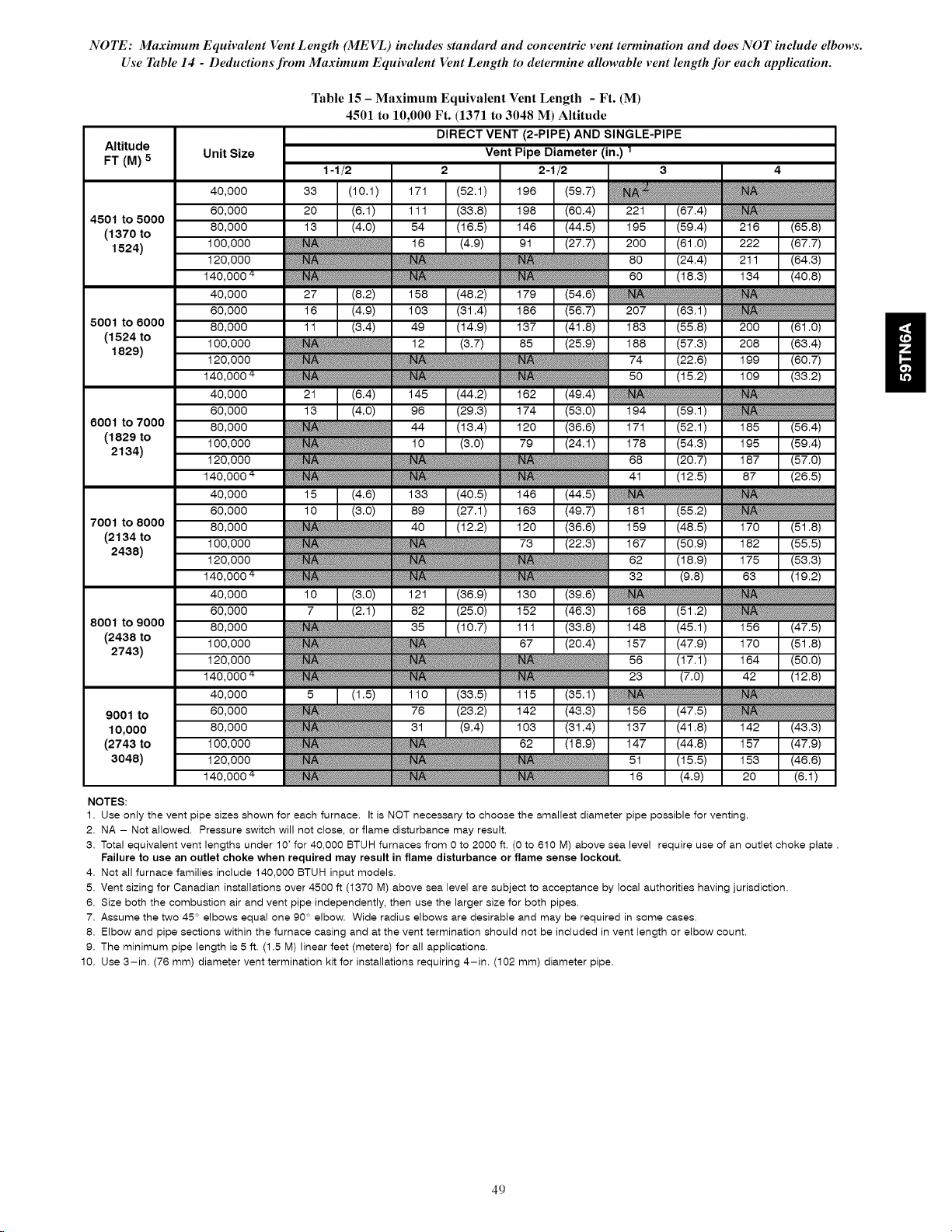
NOTE: Maximum Equivalent Vent Length (MEVL) includes standard and concentric vent termination and does NOT include elbows.
Use Table 14 - Deductions from Maximum Equivalent Vent Length to determine allowable vent length for each application.
Table 15 - Maximum Equivalent Vent Length - Ft. (M)
4501 to 10,000 Ft. (1371 to 3048 M) Altitude
Altitude
FT (M) 5
4501 to 5000
(1370 to 80,000
1524) 100,000
5001 to 8000 80,000
(1524 to 100,000
1829)
8001 to 7000 80,000
(1829 to 100,000
2134)
7001 to 8000 80,000
(2134 to 100,000
2438)
Unit Size
40,000
50,000
120,000
40,000
50,000
120,000
40,000
50,000
120,000
40,000
50,000
120,000
1-1/2 2 2-1/2 3
DIRECT VENT (2-PIPE) AND SINGLE-PIPE
Vent Pipe Diameter (in.) 1
40,000
50,000
8001 to 9000 80,000
(2438 to 100,000
2743)
9001 to 50,000
10,000 80,000
(2743 to 100,000
3048) 120,000
NOTES:
1. Use only the vent pipe sizes shown for each furnace. It is NOT necessary to choose the smallest diameter pipe possible for venting.
2. NA - Not allowed. Pressure switch will not close, or flame disturbance may result.
3. Total equivalent vent lengths under 10' for 40,000 BTUH furnaces from 0 to 2000 ft. (0 to 610 M) above sea level require use of an outlet choke plate.
Failure to use an outlet choke when required may result in flame disturbance or flame sense lockout.
4. Not all furnace families include 140,000 BTUH input models.
5. Vent sizing for Canadian installations over 4500 It (1370 M) above sea level are subject to acceptance by local authorities having jurisdiction.
6. Size both the combustion air and vent pipe independently, then use the larger size for both pipes.
7. Assume the two 45 ° elbows equal one 90 ° elbow. Wide radius elbows are desirable and may be required in some cases.
8. Elbow and pipe sections within the furnace casing and at the vent termination should not be included in vent length or elbow count.
9. The minimum pipe length is 5 ft. (1.5 M) linear feet (meters) for all applications.
10. Use 3-in. (76 mm) diameter vent termination kit for installations requiring 4-in. (102 mm) diameter pipe.
120,000
40,000
49
Page 50
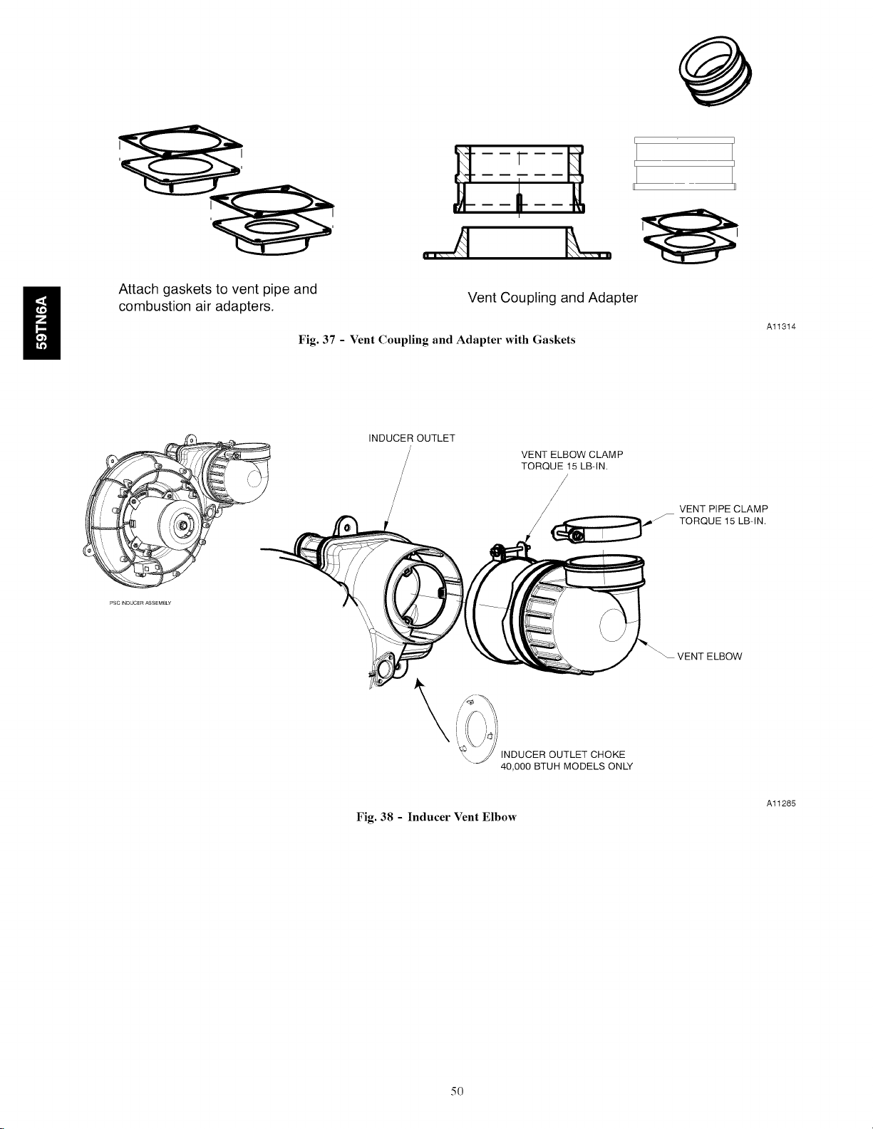
Attach gaskets to vent pipe and
combustion air adapters.
Fig. 37 - Vent Coupling and Adapter with Gaskets
Vent Coupling and Adapter
Al1314
INDUCER OUTLET
VENT ELBOW CLAMP
TORQUE 15 LB-IN.
VENT PIPE CLAMP
TORQUE 15 LB-IN.
ELBOW
Fig. 38 - Inducer Vent Elbow
50
INDUCER OUTLET CHOKE
40,000 BTUH MODELS ONLY
Al1285
Page 51
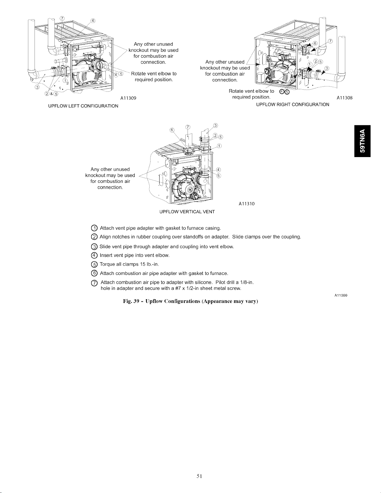
s_ r
UPFLOW LEFT CONFIGURATION
Any otherunused
knockout may be used
_rcombustion air
connedion.
Any other unused
knockout be used
may
for combustion air
connection.
Rotate vent elbow to
required position.
A11309
UPFLOW VERTICAL VENT
00 '>: : .... l k'j
Any other unused __0 &_._5)
knockout may be used _ _. - ,_
connection. _ _ _:!_"o
Rotate vent elbow to (D
required position.
UPFLOW RIGHT CONFIGURATION
A11310
A11308
C) Attach vent pipe adapter with gasket to furnace casing.
Align notches in rubber coupling over standoffs on adapter. Slide clamps over the coupling.
(_ Slide vent pipe through adapter and coupling into vent elbow.
1_ Insert vent pipe into vent elbow.
(_ Torque all clamps 15 lb.-in.
@ Attach combustion air pipe adapter with gasket to furnace.
(_ Attach combustion air pipe to adapter with silicone. Pilot drill a 1/8-in.
hole in adapter and secure with a #7 x 1/2-in sheet metal screw.
Fig. 39 - Upflow Configurations (Appearance may vary)
A11399
51
Page 52

Rotate vent elbow to
,(3_J, required position.
I
Rotate vent elbow to
required position.
Any other unused
knockout may be used
for combustion air
connection.
Al1311
Al1312
ii
DOWNFLOW LEFT CONFIGURATION
DOWNFLOW RIGHT CONFIGURATION
Al1313
Downflow Vertical
Requires Accessory Internal Vent Kit.
See Product Data for current kit number.
(_ Attach vent pipe adapter with gasket to furnace casing.
(_) Align notches in rubber coupling over standoffs on adapter. Slide clamps over the coupling.
C) Slide vent pipe through adapter and coupling into vent elbow.
(_ Insert vent pipe into vent elbow.
(_) Torque all clamps 15 lb.-in.
(_ Attach combustion air pipe adapter with gasket to furnace.
C) Attach combustion air pipe to adapter with silicone. Pilot drill a 1/8-in.
hole in adapter and secure with a #7 x 1/2-in sheet metal screw.
Fig. 40 - Downflow Configurations (Appearance may vary)
52
Al1400
Page 53

HORIZONTAL LEFT -
VERTICAL VENT CONFIGURATION
AI 1327
A11328
HORIZONTAL LEFT -
LEFT VENT CONFIGURATION
I
HORIZONTALLEFT-
Al1329
RIGHT VENT CONFIGURATION*
*RequiresAccessoryInternalVent Kit
SeeProductDatafor CurrentKitNumber
(_ Attach vent pipe adapter with gasket to furnace casing.
(_) Align notches in rubber coupling over standoffs on adapter. Slide clamps over the coupling.
Q Slide vent pipe through adapter and coupling into vent elbow.
(_ Insert vent pipe into vent elbow.
C) Torque all clamps 15 lb.-in.
(_ Attach combustion air pipe adapter with gasket to furnace.
(_) Attach combustion air pipe to adapter with silicone. Pilot drill a 1/8-in.
hole in adapter and secure with a #7 x 1/2-in sheet metal screw.
Fig. 41 - Horizontal Left (Appearance may vary)
A11340
53
Page 54

ii
-- ALTERNATE
COMBUSTION
AIR
CONNECTIONS
HORIZONTAL RIGHT -
VERTICAL VENT CONFIGURATION
Al1337
HORIZONTAL RIGHT -
LEFT VENT CONFIGURATION*
*Requires Internal Vent Kit
See Product Data for Current Kit Number
Al1336
HORIZONTAL RIGHT -
Al1335
RIGHT VENT CONFIGURATION
(_ Attach vent pipe adapter with gasket to furnace casing.
(_) Align notches in rubber coupling over standoffs on adapter. Slide clamps over the coupling.
(_) Slide vent pipe through adapter and coupling into vent elbow.
(_ Insert vent pipe into vent elbow.
(_ Torque all clamps 15 lb.-in.
C) Attach combustion air pipe adapter with gasket to furnace.
(_) Attach combustion air pipe to adapter with silicone. Pilot drill a 1/8-in.
hole in adapter and secure with a #7 x 1/2-in sheet metal screw.
Fig. 42 - Horizontal Right (Appearance may vary)
54
A11341
Page 55

VENT PIPE ADAPTER WITH GASKET
INSTALLED ON FURNACE VENT
PIPE IS CUT FLUSH WITH TOP OF
ADAPTER.
ALIGN NOTCHES IN VENT PIPE
COUPLING OVER STAND-OFF
ON ADAPTER. TORQUE LOWER
CLAMP 15 LB-IN, WHEN REMAINING
VENT PIPE IS INSTALLED, TORQUE
UPPER CLAMP TO 15 LB-IN.
VENT PIPE FLUSH WITH ADAPTER
Point elbow down towards
back of furnace
VENT PIPE FLUSH SHOWING COUPLING
Al1339
Fig. 43 - Vent Pipe Flush with Adaptor
12"
256.0 mm
CASING SIDE ATTACHMENT
COMBUSTION AIR PIPE
(NON-DIRECT VENT)
Fig. 44 - Combustion Air Pipe Attachment
J
TOP PLATE ATTACHMENT
COMBUSTION AIR PIPE
(NON-DIRECT VENT)
Al1345
55
Page 56
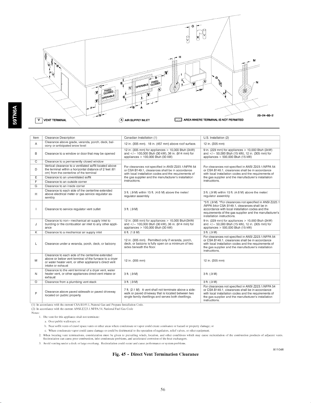
................................ /
I _ V!
Item
Clearance Description Canadian Installation (1) U.S. Installation (2)
A
Clearance above grade, veranda, porch, deck, bah 12 in. (305 ram). 18 in. (457 ram) above roof surface. 12 in. (305 ram)
cony or anticipated snow level
B
Clearance to a window or door that may be opened and </- 100,000 Btuh (30 kW), 36 in. (914 ram) for and </- 50,000 Btuh (15 kW), 12 in. (305 ram) for
C
Clearance to a permanently closed window
Vertical clearance to a ventilated soffit located above
D
the terminal within a horizontal distance of 2 feet (61
cm) from the centerline of the terminal
E
Clearance to an unventilated soffit
F
Clearance to an outside corner
G
Clearance to an inside corner
Clearance to each side of the centerline extended
H
above electrical meter or gas service regulator as-
sembly
Clearance to service regulator vent outlet
Clearance to non-mechanical air supply inlet to
J
building or the combustion air inlet to any other applb
ance
K
Clearance to a mechanical air supply inlet
L Clearance under a veranda, porch, deck, or balcony deck, or balcony is fully open on a minimum of two
Clearance to each side of the centerline extended
above or below vent terminal of the furnace to a dryer
M or water heater vent, or other appliance's direct vent 12 in. (305 ram) 12 in. (305 ram)
intake or exhaust
Clearance to the vent terminal of a dryer vent, water
N heater vent, or other appliances direct vent intake or 3 ft. (.9 M) 3 ft. (.9 M)
exhaust
O Clearance from a plumbing vent stack 3 ft. (.9 M) 3 ft. (.9 M)
p Clearance above paved sidewalk or paved driveway walk or paved driveway that is located between two with local installation codes and the requirements of
located on public property single family dwellings and serves both dwellings, the gas supplier and the manufacturer's installation
(1) In accordance with the current CSA B149.1, Natural Gas and Propane Installation Code.
(2) In accordance with the current ANSI Z223.1 .NFI'A 54, National Fuel (;as Code
Notes:
1. The vent Iklr this appliance stiall not terminate:
a. Overpub[icwa[kways: lit
b. Near so,it vents of crawl space vents or ottier areas wtiere condensa_ or vapor could create a nuisance or hazard or property damage; or
c. Where condensate vapor could cause damage or could be de_imental to the operation of regula_lrs, relief valves, or other equipment.
2. When locating vent terminations, consideration must be given to prevailing winds, location, and other conditions which may cause recirculadon of the combustion products of adjacent vents.
Recirculadon can cause poor combustion, inlet condensate problems, and accelerated co_oshm of the heat exchangers.
3. Avoid venting under a deck or large overhang. Recirculation could occur and cause per_lrmance or system problems.
12 in. (305 ram) for appliances > t0,000 Btuh (3kW) 9 in. (229 ram) for appliances > 10,000 Btuh (3kW)
appliances > 100,000 Btuh (30 kW) appliances > 500,000 Btuh (15 kW)
For clearances not specified in ANSI Z223.1/NFPA 54
or CSA B149.1, clearances shall be in accordance
with local installation codes and the requirements of
the gas supplier and the manufacturer's installation
instructions.
3 ft. (.9 M) within 15 ff. (4.6 M) above the meter/ 3 ft. (.9 M) within 15 ff. (4.6 M) above the meter/
regulator assembly regulator assembly
3 ff. (.9 M)
12 in. (305 ram) for appliances > t0,000 Btuh(3kW)
and </- 100,000 Btuh (30 kW), 36 in. (914 ram) for
appliances > 100,000 Btuh (30 kW)
5 ft. (1.8 M)
12 in. (305 ram). Permitted onty if veranda, porch,
sides beneath the floor.
7 ft. (2.1 M). A vent shall not terminate above a side- or CSA B149.1, clearances shall be in accordance
f'
/
For clearances not specified in ANSI Z223.1/NFPA 54
or CSA B149.1, clearances shall be in accordance
with local installation codes and the requirements of
the gas supplier and the manufacturer's installation
instructions.
*3 ft. (.9M) *For clearances not specified in ANSI Z223.1
/NFPA 54or CSA B149.1, clearances shall be in
accordance with local installation codes and the
requirements of the gas supplier and the manufacturer's
installation instructions.
9 in. (229 ram) for appliances > 10,000 Btuh (3kW)
and </- 50,000 Btuh (15 kW), 12 in. (305 ram) for
appliances > 500,000 Btuh (15 kW)
3 ff. (.9 M)
For clearances not specified in ANSI Z223.1/NFPA 54
or CSA B149.1, clearances shall be in accordance
with local installation codes and the requirements of
the gas supplier and the manufacturer's installation
instructions.
For clearances not specified in ANSI Z223.1/NFPA 54
instructions.
Fig. 45 - Direct Vent Termination Clearance
Al1046
56
Page 57
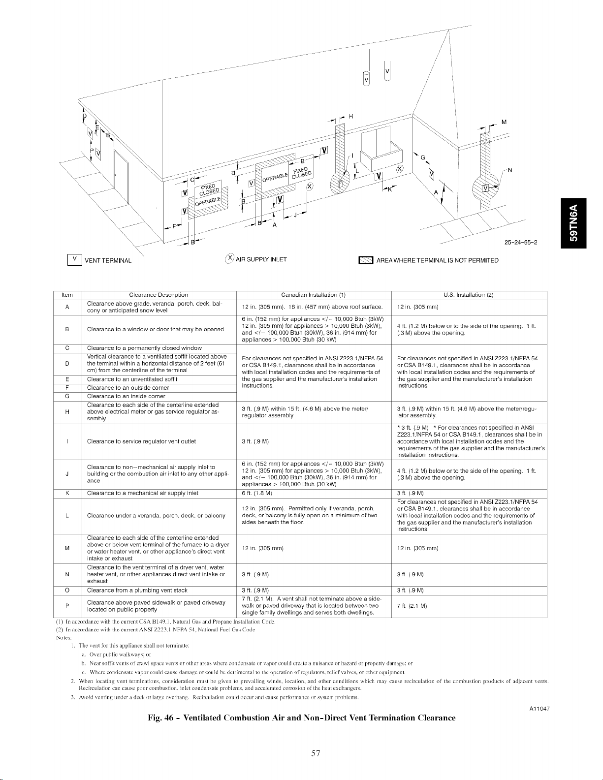
JJJJ ...... // i
/
/
/
I_ VENT TERMINAL
Item Clearance Description Canadian Installation (1) U.S. Installation (2)
A cony or anticipatedClearance above grade, veranda, porch, deck, bal-snowlevel 12 in. (305 mm). 18 in. (457 mm) above roof surface. 12 in. (305 mm)
B
Clearance to a window or door that may be opened and12 in. (305t00,000mm)forBtuhapptiances(30kW),></_36t0'000(914BtUhin,mm) for(3kw)' (.3 M) above the opening.4 ft. (t .2 M) below or to the side of the opening. 1 ft.
C
Clearance to a permanently closed window
Vertical clearance to a ventilated soffit located above
D
the terminal within a horizontal distance of 2 feet (61
cm) from the centerline of the terminal
E
Clearance to an unventilated soffit
F
Clearance to an outside corner
G
Clearance to an inside corner
Clearance to each side of the centedine extended
H
above electrical meter or gas service regulator as-
sembly
I Clearance to service regulator vent outlet 3 ft. (.9 M) accordance with local installation codes and the
Clearance to non- mechanical air suppty inlet to
J building or the combustion air inlet to any other appli- and </- t00,000 Btuh (30kW), 36 in. (914 mm) for (.3 M) above the opening.
ance appliances > 100,000 Btuh (30 kW)
K Clearance to a mechanical air supply inlet 6 ft. (1.8 M) 3 ft. (.9 M)
L Clearance under a veranda, porch, deck, or balcony deck, or balcony is fully open on a minimum of two with local installation codes and the requirements of
Clearance to each side of the centerline extended
M or water heater vent, or other appliance's direct ventab°ve or below vent terminal of the furnace to a dryer 12 in. (305 mm) 12 in.
intake or exhaust
Clearance to the vent terminal of a dryer vent, water
N heater vent, or other appliances direct vent intake or 3 ft. (.9 M) 3 ft. (.9 M)
exhaust
O Clearance from a plumbing vent stack 3 ft. (.9 M) 3 ft. (.9 M)
p Clearance above paved sidewalk or paved driveway walk or paved driveway that is located between two 7 ft. (2.1 M).
located on public property single family dwellings and serves both dwellings.
(1) In accordance witb tbe currem CSA B14_JA. Nalural (}as and Propane Insl_lllalion (_)tt_'.
(2) In accordance wilb Ibe currem ANSI Z223.] .NFPA 51. National Fuel (}as (:ode
Noles:
]. The xenl for Ibis appliance sbal] nol lerminale:
a. Over public walkways: or
b. Ne_tr so|l'il venls o| crzlwl spzlcc \ {'Ills or olber areas where ct)ndensale or vzq?tlr could create a nuisance or hazard or properly damage: or
c. Where condensale vapor could cause damage or could bc dcli-ilTlenlztl Io Ibc opcralion ill regul_llors, relivf \ zincs, iIr olhcr equipmenL
2. When localing vent lerminations, consideralion must be given Io prevailing winds, h)caliom and olber conditions which ma} cause recb'ctHation of Ibe combustion producls of adjacent venls.
Recirculalion can czttlse poor combustion, inlel cond{,nsztle problems, and act'der_ti_'d corrosion of Ibe heal excbangers.
3. Axoid xenting und{'r a deck or hirge ox erbang. Recb'cuhttion could occur and c_itlSt' pc'r|i)rmance or s_slem probh'ms.
(_' AIR SUPPLY INLET
6 in. (t52 mm) for appliances </- t0,000 Btuh (3kW)
appliances > 100,000 Btuh (30 kW)
For clearances not specified in ANSI Z223.t/NFPA 54
or CSA B149.t, clearances shall be in accordance
with local installation codes and the requirements of
the gas supplier and the manufacturer's installation
instructions.
3 ft. (.9 M) within 15 ft. (4.6 M) above the meter/ 3 ft. (.9 M) within 15 ft. (4.6 M) above the meter/regu-
regulator assembly lator assemMy.
12 in. (305 mm) for appliances>6in" (t52 mm) f°r appliances </-t0,000Btuht0'000Btuh(3k\_)(3kW), 4 ft. (t.2 M) below or to the side of the opening, lff.
12 in. (305 mm). Permitted only if veranda, porch, orCSA B149.t, clearances shall be in accordance
sides beneath the floor, the gas supplier and the manufacturer's installation
E_ AREAWHERE TERMINAL IS NOT PERMITED
For clearances not specified in ANSI Z223.t/NFPA 54
or CSA B149.t, clearances shall be in accordance
with local installation codes and the requirements of
the gas supplier and the manufacturer's installation
instructions.
* 3 ft. (.9 M) * For clearances not specified in ANSI
Z223.1/NFPA 54 or CSA B149.t, clearances shall be in
requirements of the gas supplier and the manufacturer's
installation instructions.
For clearances not specified in ANSI Z223.t/NFPA 54
instructions.
(305am)
7 ft. (2.1 M). A vent shall not terminate above a side-
Fig. 46 - Ventilated Combustion Air and Non-Direct Vent Termination Clearance
A11047
57
Page 58

Con_ntric Vent and Corn bustion Air
Roof Termination {ptefurted) ...........
clearance above
\\\\\
Fig. 47 - Combustion Air and Vent Pipe Termination for Direct Vent (2-Pipe) System
A05090
Roof Termination (Preferred)
cr_ 305mm)
mnmum earance
above highest a_licipated
snow bevel maximum of
24 in (610ram) above roof
Side walHermination
with 2 ehbows (preferred)
[i::::°i
Abandoned masonry
used as raceway
(percode)
12 in (305 ram) rain from
overhang or roof
Maintain 12 in (305ram)
minimum clearance
above highest a_licipated
snow level or grade
whichever is greater
6 in (152ram) minimum clearance
between wal[ aid end of vent pipe
10 in (254mm) maximum pipe [enql]
12 in rain (305 mm)fron
overhang or roof
Sidewall Termination
with Straight Pipe (preferred)
Fig. 48 - Vent Pipe Termination for Non-Direct Vent and Ventilated Combustion Air System
ghest anticipated
snow level or grade
whichever is greater
_O5mm)
A05091
58
Page 59

\
NOTE: This illustration is for
reference only, Your unit may
differ in appearance or may not
include all components shown.
OVERHANG OR ROOF
12-in
30A8 cm
Above anticipated
snow UeveU
/ COMBUSTION AIR
(ELBOW PARALLEL
TO WALL)
L10F024=1
UVL_IN£_
EXHAUST -I r
_ _._ ea ance to overhang per code
12 IN, SEPARATION
BETWEEN BOTTOM OF "_
COMBUSTION AIR AND
BOTTOM OF VENT
MAINTAIN 12 IN.
CLEARANCE
ABOVE HIGHEST
ANTICIPATED SNOW
LEVEL OR GRADE,
WHICHEVER IS
GREATER.
J
Fig. 49 - Alberta and Saskatchewan Vent Termination
59
Al1346
Page 60

Ventilated Combustion
// Air intake pipe _U
ii
/
-"19-_ Pipe hangar _ _ _
_ R" [7_ mm _,
Ventilated Combustion Air 12" (305 mm)
intake termination in crawl
space
CRAWL SPACE
Ventilated Combustion
Air intake pipe
Vent through
roof flashing
ATTI C
Fig. 50 - Vent Terminations for Ventilated Combustion Air
dO
ff
12" (305 ram) rain. above
highest level of insulation
A10497
Page 61

START-UP, ADJUSTMENT, AND SAFETY
CHECK
General
1. Furnace must have a 115-v power supply properly connec-
ted and grounded.
NOTE: Proper polarity must be maintained for l15-v wiring.
Control status indicator light flashes rapidly and furnace does not
operate if polarity is incorrect.
2. Thermostat wire connections at terminals R, W/WI, G, and
Y/Y2 must be made at 24-v terminal block on furnace con-
trol.
3. Natural gas service pressure must not exceed 0.5 psig (14-
in. w.c.), but must be no less than 0.16 psig (4.5-in. w.c.).
4. Blower door must be in place to complete l15-v electrical
circuit to furnace.
UNIT OPERATION HAZARD
Failure to follow this caution may result in intermittent unit
operation or performance satisfaction.
These furnaces are equipped with a manual reset limit
switch in burner assembly. This switch opens and shuts off
power to the gas valve is an overheat condition (flame
rollout) occurs in burner assembly. Correct inadequate
combustion-air supply or improper venting condition
before resetting switch. DO NOT jumper this switch.
1. Remove blower door.
2. Locate A/C setup switches on furnace control.
3. Determine air conditioning tonnage used.
4. Configure the switches for the required cooling airflow.
NOTE: Excessive airflow caused by improper A/C switch setup
may cause condensate blow-off in cooling mode.
5. Replace blower door.
Continuous Fan (CF) Setup Switches (SW3)
The CF setup switches are used to select desired airflow when
thermostat is in continuous fan mode or to select low-cooling
airflow for two-speed cooling units. This setup feature allows
continuous fan airflow or low-cooling airflow to be adjusted. To
set desired continuous fan airflow or low-cooling airflow:
1. Remove blower door.
2. Locate CF setup switches on furnace control.
3. Determine desired continuous fan airflow or low-cooling
airflow.
4. Configure the switches for the required continuous fan or
low-cooling airflow.
5. Replace blower door.
Setup Switch (SW4)
Setup switches SW4 are used for applications using a
communicating User Interface and to adjust airflow. Refer to Fig.
55 for configuration of SW4 airflow options.
Prime Condensate Trap with Water
H
Before operating furnace, check flame rollout manual reset switch
for continuity. If necessary, press button to reset switch.
EAC-I terminal is energized whenever blower operates. HUM
terminal is only energized when blower is energized in heating.
Select Setup Switch Positions
There are four sets of setup switches on the furnace control board.
These switches configure the furnace for correct application
requirement. They also select the airflow settings for Air
Conditioning and Continuous Fan CFMs.
The Setup Switch locations are shown and described on Fig. 55.
The set up switches are also shown on the unit wiring label.
Setup Switches (SW1)
The furnace control has 8 setup switches that may be set to meet
the application requirements. To set these setup switches for the
appropriate requirement:
• Remove blower door.
• Locate setup switches on furnace control.
• Configure the set-up switches as necessary for the application.
• Replace blower door.
NOTE: If a bypass humidifier is used, setup switch SWl-3 (Low
Heat Rise Adjust) should be in ON position. This compensates for
the increased temperature in return air resulting from bypass.
NOTE: If modulating dampers are used, blower motor
automatically compensates for modulating dampers.
Air Conditioning (A/C) Setup Switches (SW2)
The air conditioning setup switches are used to match furnace
airflow to cooling unit used.
To set the desired cooling airflow:
[]NIT OPERATION HAZARD
Failure to follow this caution may result in intermittent unit
operation or performance satisfaction.
Condensate trap must be PRIMED or proper draining may
not occur. The condensate trap has two internal chambers
which can ONLY be primed by pouring water into the
inducer drain side of condensate trap.
1. Remove upper and middle collector box drain plugs oppos-
ite of the condensate trap. (See Fig. 59.)
2. Connect field-supplied 1/2-in. (13 mm) OD tube to upper
collector box drain connection.
3. Insert field-supplied funnel into tube.
4. Pour one quart of water into funnel/tube. Water should run
through collector box, overfill condensate trap, and flow in-
to open field drain.
5. Remove funnel; replace collector box drain plug.
6. Connect field-supplied l/2-in. (13 mm) OD tube to middle
collector box drain port.
7. Pour one quart of water into funnel/tube. Water should run
through collector box, overfill condensate trap, and flow in-
to open field drain.
8. Remove funnel and tube from collector box and replace col-
lector box drain plug.
Purge Gas Lines
If not previously done, purge the lines after all connections have
been made and check for leaks.
61
Page 62

ii
FIRE OR EXPLOSION HAZARD
Failure to follow this warning could result in personal
injury, death, and/or property damage.
Never purge a gas line into a combustion chamber. Never
test for gas leaks with an open flame. Use a commercially
available soap solution made specifically for the detection
of leaks to check all connections. A fire or explosion may
result causing property damage, personal injury or loss of
line.
Adjustments
FIRE HAZARD
Failure to follow this warning could result in personal
injury, death and/or property damage.
DO NOT bottom out gas valve regulator adjusting screw.
This can result in unregulated manifold pressure and result
in excess overfire and heat exchanger failures.
FURNACE DAMAGE HAZARD
Failure to follow this caution may result in reduced furnace
life.
DO NOT redrill orifices. Improper drilling (burrs,
out-of-round holes, etc.) can cause excessive burner noise
and misdirection of burner flames. This can result in flame
impingement of heat exchangers, causing failures. (See Fig.
52.)
For proper operation and long term reliability, the Furnace input
rate must be within +/-2 percent of input rate on furnace rating
plate.
The gas input rate on rating plate is for installations at altitudes up
to 2000 ft. (609.6M).
In the USA., the input rating for altitudes above 2000 ft. (609.6M)
must be reduced by 2 percent for each 1000 ft. (304.8M) above sea
level. Refer to Table 16.
In Canada, the input rating must be derated by 5 percent for
altitudes of 2000 ft. (609.6M) to 4500 ft. (1371.6M) above sea
level.
To adjust manifold pressure to obtain the proper input rate, first,
determine if the furnace has the correct orifice installed. At higher
altitudes or different gas heat contents, it may be necessary to
change the factory orifice to a different orifice. Tables have been
provided in the furnace installation instructions to match the
required orifice to the manifold pressure to the heat content and
specific gravity of the gas. To do this:
a. Obtain average yearly gas heat value (at installed altitude)
from local gas supplier.
b. Obtain average yearly gas specific gravity from local gas
supplier.
c. Find installation altitude in Table 19.
d. Find closest natural gas heat value and specific gravity in
Table 19.
e. Follow heat value and specific gravity lines to point of in-
tersection to find orifice size and low-and high-heat mani-
fold pressure settings for proper operation.
f. Check and verify burner orifice size in furnace. NEVER
ASSUME ORIFICE SIZE. ALWAYS CHECK AND
VERIFY.
NOTE: For Canadian altitudes of 2000 to 4500 ft. (609.6 to
1371.6M), use USA altitudes of 2001 to 3000 ft. (609.6 to
914.4M).
NOTE: If orifice hole appears damaged or it is suspected to have
been redrilled, check orifice hole with a numbered drill bit of
correct size. Never redrill an orifice. A burr-free and squarely
aligned orifice hole is essential for proper flame characteristics.
g. Replace orifice with correct size, if required by Table 19.
Use only factory-supplied orifices. See EXAMPLE 1.
EXAMPLE 1
EXAMPLE: 0 - 2000 ft. (0 - 609.6M) altitude
Heating value = 1050 Btu/cu ft.
Specific gravity = 0.62
Therefore: Orifice No. 44
Manifold pressure: 3.4-in. w.c. for high heat, 1.4-in. w.c. for low
heat
* Furnace is shipped with No. 44 orifices. In this example, all main
burner orifices are the correct size and do not need to be changed to
obtain proper input rate.
1. Adjust manifold pressure to obtain low fire input rate. (See
Fig. 51.)
a. Turn gas valve ON/OFF switch to OFF.
b. Remove manifold pressure tap plug from gas valve.
c. Connect a water column manometer or similar device to
manifold pressure tap.
d. Turn gas valve ON/OFF switch to ON.
e. Move setup SWI--2 on furnace control to ON position to
lock furnace in low-heat operation. (See Fig. 55 and Fig.
35.)
f. Manually close blower door switch.
g. Jumper R and W/WI thermostat connections on control to
start furnace. (See Fig. 35.)
h. Remove regulator adjustment cap from low heat gas valve
pressure regulator (See Fig. 51) and turn low-heat adjust-
ing screw (3/16 or smaller fiat-tipped screwdriver) coun-
terclockwise (out) to decrease input rate or clockwise (in)
to increase input rate.
NOTE: DO NOT set low-heat manifold pressure less than 1.3-in.
W.C. or more than 1.7-in. W.C. for natural gas. If manifold
pressure is outside this range, change main burner orifices.
i. Install low-heat regulator adjustment cap.
j. Move setup switch SW1-2 to offposition after completing
low-heat adjustment.
k. Leave manometer or similar device connected and proceed
to Step 4.
2. Adjust manifold pressure to obtain high fire input rate. (See
Fig. 51.)
a. Jumper R to W/WI and W2 thermostat connections on fur-
nace control. This keeps furnace locked in high-heat oper-
ation.
b. Remove regulator adjustment cap from high-heat gas
valve pressure regulator (See Fig. 51) and turn high heat
adjusting screw (3/16-in. or smaller fiat-tipped screw-
driver) counterclockwise (out) to decrease input rate or
clockwise (in) to increase input rate.
NOTE: DO NOT set high-heat manifold pressure less than
3.2-in. W.C. or more than 3.8 in. W.C. for natural gas. If manifold
pressure is outside this range, change main burner orifices to obtain
manifold pressure in this range.
62
Page 63

c.Whencorrectinputisobtained,replacecapsthatconceal
gasvalveregulatoradjustmentscrews.Mainburnerflame
shouldbeclearblue,almosttransparent(SeeFig.57.)
d.RemovejumpersRtoW/WIandRtoW2.
3.Verifynaturalgasinputratebyclockingmeter.
a.Turnoffallothergasappliancesandpilotsservedbythe
meter.
b.MovesetupswitchSWI-2toONposition.Thiskeepsfur-
nacelockedinlow-heatoperation.
c.JumperRtoW/WI.
d.Runfurnacefor3minutesinlow-heatoperation.
e.Measuretime(insec)forgasmetertocomplete1revolu-
tionandnotereading.The2or5cubicfeetdialprovides
amoreaccuratemeasurementofgasflow.
f. RefertoTable18forcubicft.ofgasperhr.
g. Multiplygasratecuft./hrbyheatingvalue(Btuh/cuft.)
toobtaininput.Ifclockedratedoesnotmatchrequiredin-
putfromStep1,increasemanifoldpressuretoincreasein-
putordecreasemanifoldpressuretodecreaseinput.Repeat
stepsbthrougheuntilcorrectlow-heatinputisachieved.
Re-installlowheatregulatorsealcapongasvalve.
h.MovesetupswitchSWI-2toOFFpositionandjumperR
toW/WI,andW2.Repeatitemsdthroughgforhigh-heat
operation.
Adjust Temperature Rise
NOTE: Blower door must be installed when taking temperature
rise reading. Leaving blower door off will result in incorrect
temperature measurements.
specified on furnace rating plate. If temperature rise is out-
side this range, proceed as follows:
(1.) Check gas input for low- and high-heat operation.
(2.) Check derate for altitude if applicable.
(3.) Check all return and supply ducts for excessive
restrictions causing static pressure greater than
0.5-In. W.C.
(40 Ensure Low Heat Rise Adjust switch SWl-3 on
furnace control is in ON position when a bypass
humidifier is used. (See Fig. 35 for switch loca-
tion.)
(5.) Make sure proper model plug is installed.
d.
Remove thermostat jumpers and release blower door
switch.
e.
Repeat Steps a through c as required to adjust for high heat
temperature rise.
f.
When correct high heat input rate and temperature rise is
achieved, turn gas valve ON/OFF switch to OFF.
Release blower door switch.
g.
h.
Remove manometer or similar device from gas valve.
i.
Re-install manifold pressure tap plug in gas valve. (See
Fig. 510
FIRE HAZARD
Failure to follow this warning could result in personal
iniury, death, and/or property damage.
Reinstall manifold pressure tap plug in gas valve to prevent
gas leak.
ii
FURNACE DAMAGE HAZARD
Failure to follow this caution may result in:
• Overheating the heat exchangers or condensing flue gases
in heat exchanger areas not designed for condensate,
• Shortened furnace life
• Component damage.
Temperature rise must be within limits specified on furnace
rating plate. Recommended operation is at midpoint of rise
range or slightly above.
When setup switch SW1-4 is ON, operation will be near the high
end of the rise range for improved comfort.
Furnace must operate within ranges of temperature rise specified
on the furnace rating plate. Determine air temperature rise as
follows:
a. Place thermometers in return and supply ducts as near fur-
nace as possible. Be sure thermometers do not see heat ex-
changer so that radiant heat does not affect readings. This
practice is particularly important with straight-run ducts.
b. When thermometer readings stabilize, subtract return-air
temperature from supply-air temperature to determine air
temperature rise.
NOTE: Temperature rise can be determined for low-heat
operation by placing setup switch SWI-2 on furnace control in
ON position. For high-heat operation, place setup switch SWI-2
in OFF position and jumper R-W2 on furnace control. DO NOT
forget to return setup switch to OFF position and remove R-W2
jumper upon completion of testing.
c. This furnace is capable of automatically providing proper
airflow to maintain the temperature rise within the range
j. Remove thermostat jumper wire from furnace control
board.
k. Turn gas valve ON/OFF switch to ON.
1. Proceed to "Set Blower Off Delay" before installing
blower door.
Adjust Blower Off Delay (Heat Mode)
a. Remove blower door if installed.
b. Turn Dip switch SW-7 or SW-8 ON or OFF for desired
blower off delay. (See Table 17 and Fig. 35, Fig. 55 and
Fig. 64.)
Adjust Cooling Airflow - High-Speed and
Low-Speed Cooling
The ECM blower can be adjusted for a range of airflows for
low-speed or high-speed cooling. See Table 7 - Air Delivery -
CFM (With Filter ) and Fig. 55 - Furnace Setup Switches and
Descriptions. Depending on the model size, the cooling airflow
can be adjusted from 1.5 to 6 tons based on 350 CFM ton.
NOTE: 6 ton airflow will truncate at 2200 CFM on applicable
models.
The high-speed or single-speed cooling airflow is adjusted by
turning Setup switches SW2-1, SW2-2 and SW2-3 either ON or
OFF. Select the required airflow from Table 7. Table 7 is based
upon 350 CFM per ton. For other CFM per ton Setup switch
selections, see Fig. 35, Fig. 55 and Fig. 64.
The Continuous Fan airflow selection via Setup switches SW3 is
also the airflow for low-speed cooling when the furnace is used
with a 2-speed cooling or heat pump unit. Adjust the Continuous
Fan CFM Setup switches SW3 to match the airflow required for
low-speed cooling. Select the required airflow from Table 7 and
Fig. 55.
63
Page 64
ii
NOTE: The airflow selected via SW3 (Low-Speed Cooling
Airflow) cannot exceed the airflow selected via SW2 (High-Speed
Cooling Airflow). For other CFM per ton Setup switch selections,
see Fig. 35 and Fig. 55.
NOTE: The airflow settings for SW2 and SW3 selections are the
same, EXCEPT for the default values. See Table 7.
For a complete explanation of cooling airflow, refer to the section
titled "Sequence of Operation."
Adjust Continuous Fan Airflow (and Low-Speed
Cooling Airflow)
NOTE: When the furnace is used with a 2-speed cooling or heat
pump unit, the airflow selected for continuous fan via Setup switch
SW3 will also be the airflow used for low-speed cooling, and vice
versa. The continuous fan speed can be further adjusted at a
conventional thermostat using the continuous fan speed select
function. Changing the continuous fan speed at a conventional
thermostat DOES NOT change the low-speed cooling airflow
selected via SW3 at the control board.
NOTE: When the furnace is used with a 2-speed cooling or heat
pump unit, adjust the Continuous Fan CFM Setup switches SW3
to match the airflow required for low-speed cooling.
Select the required continuous fan airflow using Setup switches
SW3 as shown in Fig. 55 and Table 7.
Adjust Thermostat Heat Anticipator.
a. Mechanical thermostat. Set thermostat heat anticipator to
match the amp. draw of the electrical components in the
R-W/W1 circuit. Accurate amp. draw readings can be ob-
tained at the wires normally connected to thermostat sub-
base terminals, R and W.The thermostat anticipator should
NOT be in the circuit while measuring current.
(1.) Set SWl-2 switch on furnace control board to ON.
(2.) Remove thermostat from subbase or from wall.
(3.) Connect an amp. meter as shown in Fig. 53 across
the R and W subbase terminals or R and W wires
at wall.
(4.) Record amp. draw across terminals when furnace is
in low heat and after blower starts.
(5.) Set heat anticipator on thermostat per thermostat
instructions and install on subbase or wall.
(6.) Turn SWl-2 switch OFF.
(7.) Install blower door.
b. Electronic thermostat: Set cycle rate for 3 cycles per hr.
Check Safety Controls
The flame sensor, gas valve, and pressure switch were all checked
in the Start-up procedure section as part of normal operation.
1. Check Main Limit Switch
This control shuts off combustion system and energizes air-
circulating blower motor, if furnace overheats. By using this
method to check limit control, it can be established that lim-
it is functioning properly and will operate if there is a re-
stricted return-air supply or motor failure. If limit control
does not function during this test, cause must be determined
and corrected.
a. Run furnace for at least 5 minutes.
b. Gradually block off return air with a piece of cardboard or
sheet metal until the limit trips.
c. Unblock return air to permit normal circulation.
d. Burners will re-light when furnace cools down.
2. Check Pressure Switch(es)
This control proves operation of the draft inducer blower.
a. Turn off 115-v power to furnace.
b. Disconnect inducer motor lead wires from wire harness.
c. Turn on 115-v power to furnace.
d. Set thermostat to "call for heat" and wait 1 minute. When
pressure switch is functioning properly, hot surface igniter
should NOT glow and control diagnostic light flashes a
status code 32. If hot surface igniter glows when inducer
motor is disconnected, shut down furnace immediately.
e. Determine reason pressure switch did not function prop-
erly and correct condition.
f. Turn off 115-v power to furnace.
g. Reconnect inducer motor wires, replace door, and turn on
115-v power.
h. Blower will run for 90 sec before beginning the call for heat
again.
i. Furnace should ignite normally.
Checklist
1. Put away tools and instruments. Clean up debris.
2. Verify that switches SWl-1 and SWl-6 are OFF and other
setup switches are set as desired. Verify that switches
SWl-7 and SWl-8 for the blower OFF DELAY are set as
desired per Table 17.
3. Verify that blower and control doors are properly installed.
4. Cycle test furnace with room thermostat.
5. Check operation of accessories per manufacturer's instruc-
tions.
6. Review Owner's Manual with owner.
7. Attach literature packet to furnace.
64
Page 65
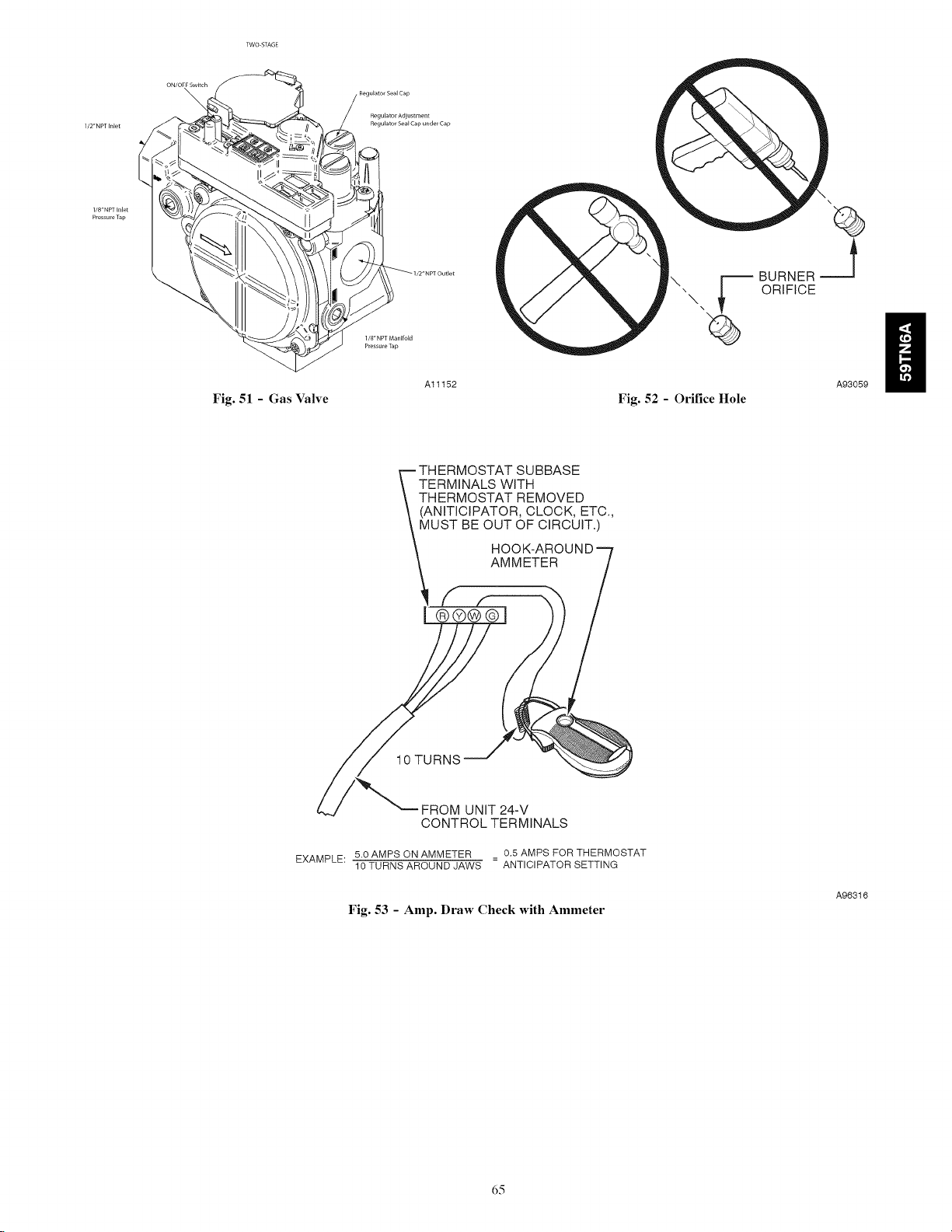
\
Regulator Adjustment
Regulator Seal Cap under Cap
l/8"NPTInlet
Pressu[eTap
Fig. 51 - Gas Valve
Al1152
THERMOSTAT SUBBASE
TERMINALS WITH
THERMOSTAT REMOVED
(ANITICIPATOR, CLOCK, ETC.,
MUST BE OUT OF CIRCUIT.)
\
BURNER
ORIFICE
A93059
Fig. 52 - Orifice Hole
FROM UNiT 24-V
CONTROL TERMINALS
EXAMPLE: 5.0 AMPS ON AMMETER = 0,5 AMPS FOR THERMOSTAT
10 TURNS AROUND JAWS ANTICIPATOR SETTING
Fig. 53 - Amp. Draw Check with Ammeter
d5
A96316
Page 66

SERVICE
.......... Ifsta_scodereceiisnaededd_ned _ 'R"_ lead,reseti:x:,,_,_,andputsebpswitch"SWI-1"
in_eONposi_::_.Todearfnastatuscodehisto._/putse_ sv,_ch"SWl-l"in_naON_ andju_
LED CODE STATUS
CONTINUOUS OFF - Checkfor115VACatL1andL2,and24VACatSEC-landSEC-2.
CONTINUOUS ON- C,X_ntrolhas24VAC_.
_P|D FLASHING Unevoltage(115VAC)polarityisreversed.
EACHOFTHEFOLLOWINGSTATUSCODESISASINGLEORTWODIGITNUMBERWITHTHEFIRSTNUMBERDETERMINEDBYTHE
NUMBEROFSHORTFLASHESANDTHESECONDNUMBERAFTERTHEPLUS(+)SIGNISTHENUMBEROFLONGFLASHES,
11NOPREVIOUSCODE.Storedstatuscodesareerasedautomaticallyafter72hoursorasspecifiedabove,
12BLOWERONAFTERPOWERUP.(115VACor24VAC)-Blowerrunsfor90seconds,ifunitispoweredupduringa
callforheat(R.W/W1closed)or(R.W/W1opens)duringtheblowerondelayperiod,
13LIMITCIRCUITLOCKOUT.Lockoutoccursifthelimit,orflamerolloutswitchisopenlongerthan3minutesor
10successivelimittripsoccurredduringhigh-heat,Controlwillautoresetafter3hours,Refertostatuscode#33,
14IGNITIONLOCKOUT.Controlwillauto-resetafter3hours,Refertostatuscode#34,
15BLOWERMOTORLOCKOUT.Indicatestheblowerfailedtoreach250RPMortheblowerfailedtocommunicatewithin30
secondsafterbeingturnedONintwosuccessiveheatingcycles,Controlwillautoresetafter3hours,Refertostatuscode#41,
21 GASHEATINGLOCKOUT.ControlwillNOTautoreset,Checkfor:-Mis-wiredgasvalve,-Defectivecontrol(valverelay)
22ABNORMALFLAME.PROVINGSIGNAL.Flameisprovedwhilegasvalveisde.energized,Inducerwillrununtilfault
iscleared,Checkfor: -Leakygasvalve, - Stuck.opengasvalve,
23 PRESSURESWITCHDIDNOTOPEN-Checkfor:-Obstructedpressuretubing,-Pressureswitchstuckclosed,
24 SECONDARYMOLTAGEFUBEISOPEN-Checkfor:-Shortcircuifinsecondaryvoltage(24VAC)widng,
25 MODELSELECTIONORSETUPERROR-Eitherindicatesthemodelplug(PL4)ismissingorincorrectorsetupswitch
"SW1.1"or"SWl-6"ispositionedimproperly,Ifcodeflashesonly4timesonpower-upcontrolisdefaultingtomodelselection
31 HIGH.HEATPRESSURESWITCHORRELAYDIDNOTCLOSEORREOPENED• Indicatesthehigh-heatpressureswitch
inputfailedtocloseoropenedduringhigh-heat,Controlrelaymaybedefectiveorgasvalveismis-wired,Refertostatus
code#32,
32LOW.HEATPRESSURESWffOHDIDNOTCLOSEORREOPENED.Indicatesthelow-heatpressureswitchinputfailedto
closeonacallforlow-heat,oropenedduringlow-heat,Ifopensduring5minutesafterignitionthenextheatingcyclewillbe
restrictedtohigh-heat,Checkfor: - Properventsizing, -Excessivewind, -Pluggedcondensatedrain,
-Lowinletgaspressure(ifLGPSused), -Restrictedcombustionairsupply, -Improperpressureswitchwiring,
-Waterinventpiping,possiblesaggingpipe. -Disconnectedorobstructedpressuretubing.
-Failedor"Out.d-Calibration"pressureswitches.
33LIMITCIRCUITFAULT.Indicatesthelimit,orflamerolloutisopenorthefurnaceisoperatinginhigh-heatonlymodedueto
2successivelowheatlimittrips.Blowerwillrunfor4minutesoruntilopenswitchremakeswhicheverislonger.Ifopen
longerthan3minutes,codechangestolockout#13.Ifopenlessthan3minutesstatuscode#33continuestoflashuntil
blowershutsoff.Flamerolloutswitchrequiresmanualreset.Checkfor:.Improperlimitswflchornolimitgasket
-Defectiveswitchorconnections. -Looseblowerwheel.
-Improperlow-heatorhigh-heatgasinputadjustment. -Stuckhigh-heatsolenoidingasvalve.
34 IGNfflONPROVINGFAULT. Oontrolwilltrythreemoretimesbeforealockout#14occurs.Ifflamesignalislostduringblower
on-delaypedod,blowerwillcomeonfortheselectedbloweroff-delay.Checkfor: -Gasvalvedefectiveorturned"OFF".
-DefectiveHotBur[aceIgniter.-Manualvalveshut.off. -Lowinletgaspressure.-Flamesensormustnotbegrounded.
-Controlgroundcontinuity.-Inadequateflamecarryoverorroughignition.
-Green/YellowwireMUSTbeconnectedtofurnacesheetmetal.-Oxidebuilduponflamesensor(cleanwithfinesteelwool).
-Properflamesensemicroamps(.5microampsDOTin,4.0-6.0nominal).
41 BLOWERMOTORFAULT.Indicatestheblowerfailedtoreach250RPMortheblowerfailedtocommunicatewithin
theprescribedtimelimits.ThirtysecondsafterbeingturnedONortensecondsduringsteady-stateoperation.
43 LOW,HEATPRESSURESWITCHOPENWHILEHIGH.HEATPRESSURESWITCHISCLOSED,Checkfor:
-Pluggedcondensatedrain,-Lowinletgaspressure(ifLGPSused),-Waterinventpiping,possiblysaggingpipe,
-Improperpressureswitchwiring, -Stuckopenlow-heatpressureswitch,-Disconnectedorobstructedpressuretubing,
45CONTROLCIRCUITRYLOCKOUT-Auto-resetafterlhourlockoutdueto:-Flamesensecircuitfailure,
-Gasvalverelaystuckopen, -Softwarecheckerror,
Resetpowertoclearlockout,Replacecontrolifstatuscoderepeats,
_1 CONPONENT TEST
Toinitiatethecomponenttestsequence,shut"OFF"theroomthermostatordisconnectthe"R"thermostat
lead.Resetpowerandthenputsetupswitch"SW1-6"intheONpositiontostartthecomponenttest
sequence.OnceinitiatedthefurnacecontrolwillturntheinducerON.Theinducermotorwillrunforthe
entiretest.ThehotsurfaceigniterandblowermotorwillbeturnedONfor15secondseach.Whenthe
bloweristurnedOFFtheinducerwillbeturnedOFF.Whenthecomponenttestiscompletedoneormore
ofthefollowingcodeswillflash.
.... 25SETUPERROR-Sameascode25above,
.... completedputsetupswitch"SW1-6"intheOFFpositionendreconnectthe"R"thermostatlead.
_t terminals"R",'WNV1",and'Y/Y2'sJ_l_aneouslyun_]sta_scode#11is_shed.
storedinmemory,Checkthefollowing:-Thermostatcallwith"SWl-I"ON, -Thermostatcallwith°SW1-6"OH,
-°SWI-I"and"SWl-6"bothONtogether, -Twodifferentfurnacemodelstwinned,
-SeeRatingPlateformodelplugnumberandresistancevaluesifcodeflashescontinuously,
CODE DESCRIPTION
11IndicatesblowermotortestedOK,Visualcheckofhotsurfaceigniterandinducerrequired,
418LOWERMOTORFAULT-Indicatesblowermotorfailedtest,Checkblower,wiring,andfurnacecontrol,
.... Torepeatcomponenttestturnsetupswitch"SW1-6"OFFandthenbackON,Aftercomponenttestis
Fig. 54 - Service Label Information
dd
338308-201Re_ E
A11596
Page 67

Model Size
060-14
080-14
060-20
080-20
100-22
120-22
Model Size
060-14
080-14
060-20
080-20
100-22
120-22
Model Size
NOMINAL AIRFLOW BASED ON 350 CFM/TON (Factory Default - SW1-5 = OFF, SW4-3 = OFF)
SW2 Clg Default SW3 CF Default COOLING (SW2) AND CONTINUOUS FAN (SW3) AIRFLOW: SET-UP SWITCH POSITIONS
1050
1050
1750
1750
1750
1750
33 2 1N
2 1 N
525
525
700
700
700
875
3 2 1 N
525
525
700
700
700
700
3 2 I N
700
700
875
875
875
875
3 2 1N
875
875
1050
1050
1050
1050
3 2 1N
1050
1050
1225
1225
1225
1225
3 2 1 N
1225
1225
1400
1400
1400
1400
3 2 1N 3 2 1N
1225 1225
1225 1225
1750 1750
1750 1750
1750 2100
1750 2100
NOMINAL AIRFLOW BASED ON 400 CFM/TON (SW1=5 = ON, SW4=3 = OFF)
SW2 Dig DeDult
3 2 1 N
1200
1200
2000
2000
2000
2000
SW3 CF Default COOLING (SW2) AND CONTINUOUS FAN (SW3) AIRFLOW: SET-UP SWITCH POSITIONS
3 2 1N
600
600
800
800
800
1000
3 2 1N
60O
600
800
80O
80O
80O
3 2 I N
800
800
1000
1000
1000
1000
3 2 1N
1000
1000
1200
1200
1200
1200
3 2 1N
1200
1200
1400
1400
1400
1400
3 2 1N
1400
1400
1600
1600
1600
1600
3 2 1N
1400
1400
2000
2000
2000
2000
NOMINAL AIRFLOW BASED ON 325 CFM/TON (SW1=5 = OFF, SW4=3 = ON)
SW2 CIg Default
SW3 CF Default COOLING (SW2) AND CONTINUOUS FAN (SW3) AIRFLOW: SET-UP SWITCH POSITIONS
3 2 t N
1400
1400
2000
2000
2100
2100
060-14
080-14
060-20
080-20
100-22
120-22
Model Size
060-14
080-14
06O-2O
080-20
100-22
120-22
3 2 1N
976
976
1627
1627
1627
1627
3 2 1N
488
488
651
651
651
814
3 2 1N
488
488
651
651
651
651
3 2 1 N
651
651
814
814
814
814
3 2 1 N
814
814
976
976
976
976
3 2 1 N
976
976
1139
1139
1139
1139
3 2 1 N
1139
1139
1302
1302
1302
1302
NOMINAL AIRFLOW BASED ON 370 CFM/TON (SWI-5 = ON, SW4-3 = ON)
SW2 Dig DeDult SW3
CF Default COOLING (SW2) AND CONTINUOUS FAN (SW3) AIRFLOW: SET-UP SWITCH POSITIONS
3 2 1N 3 2 1N 3 2 1N 3 2 I N 3 2 1N 3 2 1N 3 2 1N
1116 558 558 744 930 1116 1302
1116 558 558 744 930 1116 1302
1860 744 744 930 1116 1302 1488
1860 744 744 930 1116 1302 1488
1860 744 744 930 II16 1302 1488
1860 930 744 930 1116 1302 1488
Fig. 55 - Furnace Setup Switches and Description
3 2 1 N
1139
1139
1627
1627
1627
1627
3 2 1N
1302
1302
1860
1860
1860
1860
3 2 1 N
1139
1139
1627
1627
1953
1953
3 2 1 N
1302
1302
1860
1860
2100
2100
Al1623
d7
Page 68
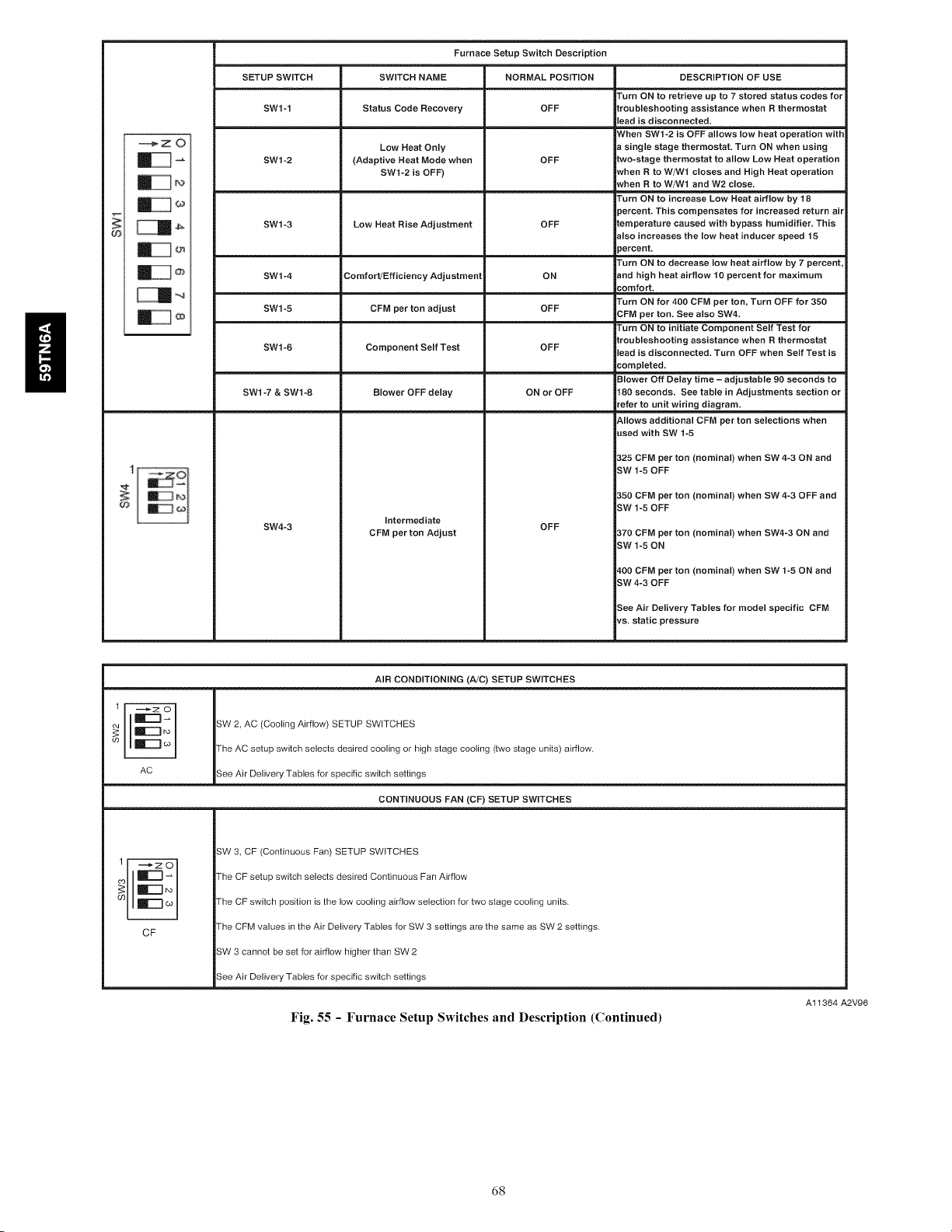
H
IZ®i
SETUP SWITCH
SWI-1
SW1-2
SW1-3
SW1-4
SW1-5
SW1-6
SW1-7 & SW1-8
SW4-3
Furnace Setup Switch Description
SWITCH NAME
Status Code Recovery
Low Heat Only
(Adaptive Heat Mode when
SW1-2 is OFF)
Low Heat Rise Adjustment
Comfort/Efficiency Adjustment
CFM per ton adjust
Component Self Test
Blower OFF delay
Intermediate
CFM per ton Adjust
NORMAL POSITION
OFF
OFF
OFF
ON
OFF
OFF
ON or OFF
OFF
DESCRIPTION OF USE
I'urn ON to retrieve up to 7 stored status codes for
iroubleshooting assistance when R thermostat
ead is disconnected.
_Vhen SWl-2 is OFF allows low heat operation witf
single stage thermostat. Turn ON when using
Ewo-stage thermostat to allow Low Heat operation
Nhen R to W/Wf closes and High Heat operation
Nhen R to W/W1 and W2 close.
I'urn ON to increase Low Heat airflow by 18
3ercent. This compensates for increased return ail
Eemperature caused with bypass humidifier. This
€lso increases the low heat inducer speed 15
3ercent.
I'urn ON to decrease low heat airflow by 7 percent.
end high heat airflow 10 percent for maximum
comfort.
I'urn ON for 400 CFM per ton, Turn OFF for 350
_FM per ton. See also SW4.
I'urn ON to initiate Component Self Test for
:roubleshooting assistance when R thermostat
ead is disconnected. Turn OFF when Self Test is
,'ompleted.
3lower Off Delay time - adjustable 90 seconds to
180 seconds. See table in Adjustments section or
"efer to unit wiring diagram.
&llows additional CFM per ton selections when
Jaed with SW 1-5
325 CFM per ton (nominal) when SW 4-3 ON and
-3W 1-5 OFF
350 CFM per ton (nominal) when SW 4-3 OFF and
-3W 1-5 OFF
370 CFM per ton (nominal) when SW4-3 ON and
-3W 1-5 ON
_,00 CFM per ton (nominal) when SW 1-5 ON and
-3W4-3 OFF
See Air Delivery Tables for model specific CFM
_a. static pressure
.......,,,,,,,,,,,,,,
1 --
_zO
ir-q_
m
(o
AC
1 _zO
m mF"l co
CF
AIR CONDITIONING (A/C) SETUP SWITCHES
3W 2, AC (Cooling Airflow) SETUP SWITCHES
I-he AC setup switch selects desired cooling or high stage cooling (two stage units) airflow.
3ee Air Delivery Tables for specific switch settings
CONTINUOUS FAN (CF) SETUP SWITCHES
i
iSW 3, CF (Continuous Fan) SETUP SWITCHES
!The CF setup switch selects desired Continuous Fan Airflow
l-he CF switch position is the low cooling airflow selection for two stage cooling units.
Fhe CFM values in the Air Delivery Tables for SW 3 settings are the same as SW 2 settings.
!SW 3 cannot be set for airflow higher than SW 2
3ee Air Delivery Tables for specific switch settings
Fig. 55 - Furnace Setup Switches and Description (Continued)
A11364 A2V96
d8
Page 69
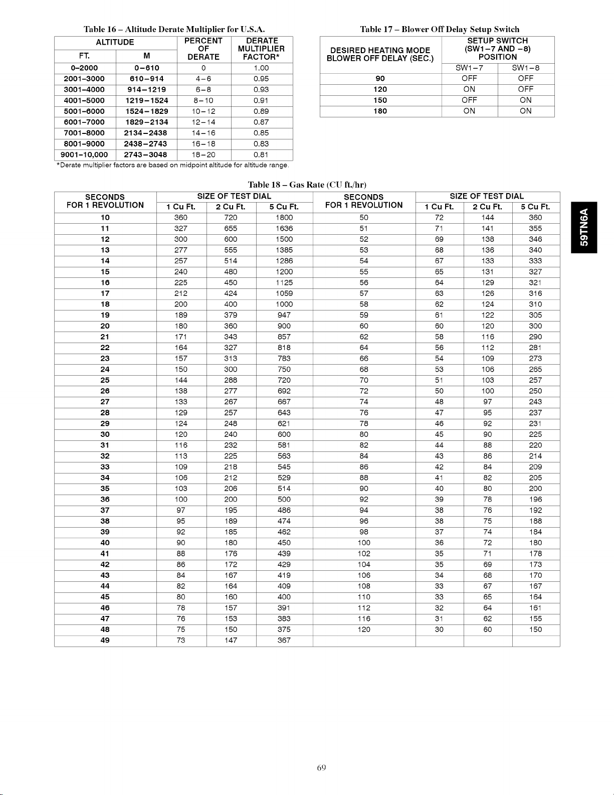
Table16- Altitude Derate Multiplier for U.S.A.
ALTITUDE PERCENT DERATE
FZ
0-2000
2001-3000
3001-4000
4001-5000
5001-8000
8001-7000
7001-8000
8001-9000
9001-10,000
*Derate multiplier factors are based on midpoint altitude for altitude range.
SECONDS
FOR 1 REVOLUTION
10
11
12
13
14
15
18
17
18
19
20
21
22
23
24
25
28
27
28
29
30
31
32
33
34
35
38
37
38
39
40
41
42
43
44
45
48
47
48
49
M
0-810
810-914
914-1219
1219-1524
1524-1829
1829-2134
2134-2438
2438-2743
2743-3048
OF
DERATE
0
4-6
6-8
8-10
10-12
12-14
14-16
16-18
18-20
MULTIPLIER
FACTOR*
1.00
0.95
0.96
0.91
0.89
0.87
0.85
0.83
0.81
Table 18 - Gas Rate (CU ft./hr)
SIZE OF TEST DIAL SECONDS
Cu Ft. 2 Cu Ft. 5 Cu Ft. FOR 1 REVOLUTION
660 720 1800 50
627 655 1636 51
300 600 1500 52
277 555 1385 56
257 514 1286 54
240 480 1200 55
225 450 1125 56
212 424 1059 57
200 400 1000 58
189 679 947 59
180 660 900 60
171 343 857 62
164 627 818 64
157 313 783 66
150 300 750 68
144 288 720 70
168 277 692 72
136 267 667 74
129 257 646 76
124 248 621 78
120 240 600 80
116 262 581 82
116 225 566 84
109 218 545 86
106 212 529 88
103 206 514 90
100 200 500 92
97 195 486 94
95 189 474 96
92 185 462 98
90 180 450 100
88 176 469 102
86 172 429 104
84 167 419 106
82 164 409 108
80 160 400 110
78 157 391 112
76 153 383 116
75 150 675 120
73 147 367
Table 17 - Blower Off Delay Setup Switch
DESIRED HEATING MODE
BLOWER OFF DELAY (SEC.)
9O
120
150
180
SETUP SWITCH
(SW1-7 AND -8)
POSITION
SW1-7 SW1-8
OFF OFF
ON OFF
OFF ON
ON ON
SIZE OF TEST DIAL
1Cu Ft. 2 Cu Ft.
72 144
71 141
69 138
68 136
67 133
65 131
64 129
63 126
62 124
61 122
60 120
58 116
56 112
54 109
53 106
51 103
50 100
48 97
47 95
46 92
45 90
44 88
43 86
42 84
41 82
40 80
39 78
38 76
38 75
37 74
36 72
35 71
35 69
34 68
33 67
33 65
32 64
31 62
30 60
5 Cu Ft.
36O
355
346
34O
333
327
321
316
310
3O5
3OO
29O
281
273
265
257
25O
243
237
231
225
22O
214
2O9
2O5
2OO
196
192
188
184
18O
178
173
17O
167
164
161
155
15O
69
Page 70
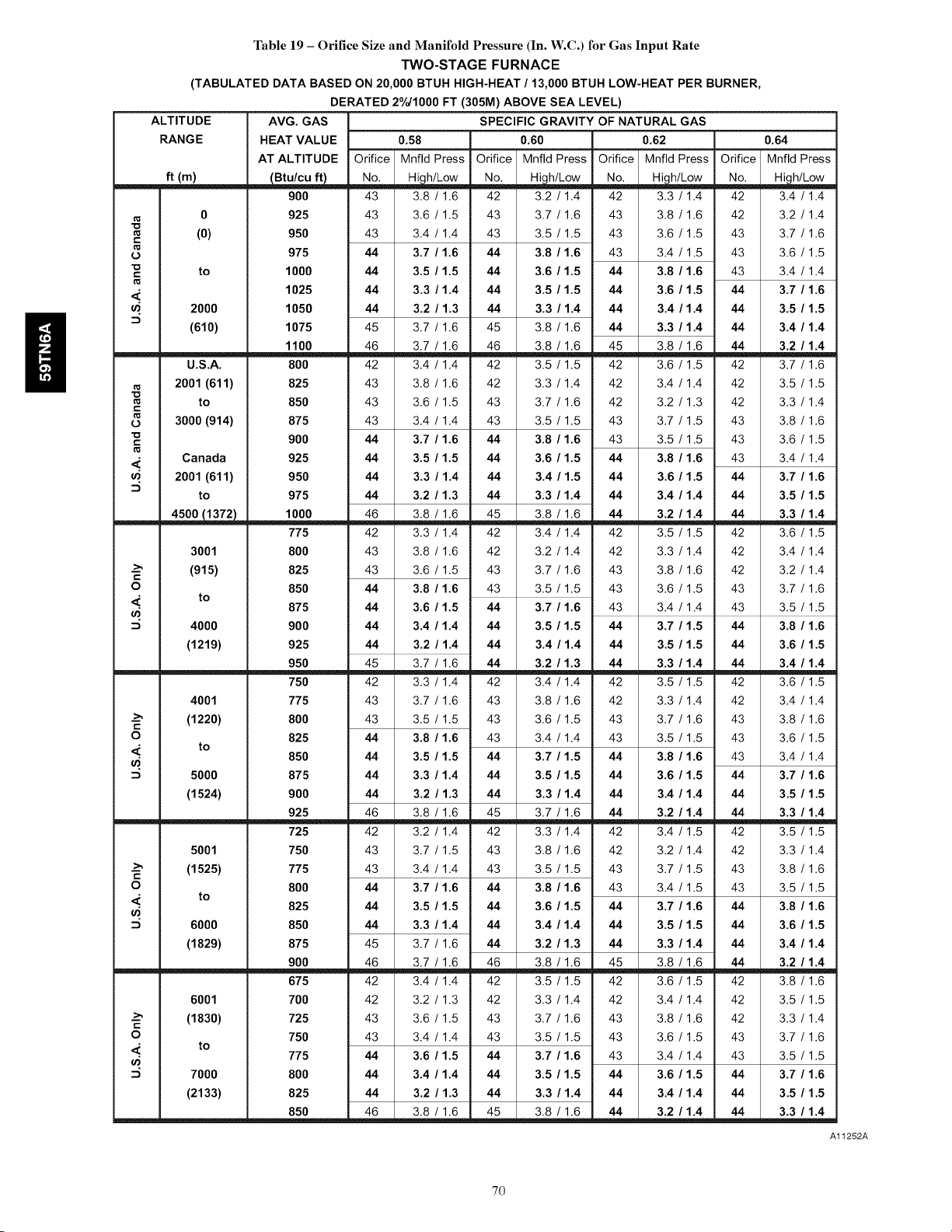
ii
Table 19 - Orifice Size and Manifold Pressure (In. W.C.) for Gas Input Rate
TWO-STAGE FURNACE
(TABULATED DATA BASED ON 20,000 BTUH HIGH-HEAT/13,000 BTUH LOW-HEAT PER BURNER,
DERATED 2%/1000 FT (305M) ABOVE SEA LEVEL)
ALTITUDE AVG. GAS SPECIFIC GRAVITY OF NATURAL GAS
RANGE HEAT VALUE 0.58 0.60 0.62 0.64
AT ALTITUDE Orifice Mnfld Press Orifice Mnfld Press Orifice Mnfld Press Orifice Mnfld Press
ft (m) _ No......___h/Low Noi Hi,.h/Low Noi Hi,.h/Low Noi High/Low
900 43 3.8 / 116 42 3.2 / 114 42 3.3 / 114 42 3.4 / 114
0 925 43 3.6 / 1.5 43 3.7 / 1.6 43 3.8 / 1.6 42 3.2 / 1.4
t..
_. 1025 44 3.3 / 1.4 44 3.5 / 1.5 44 3.6 / 1.5 44 3.7 / 1.6
t..
L_
__ 1000 46 3.8 / 1.6 45 3.8 / 1.6 44 3.2 / 1.4 44 3.3 / 1.4
.-_ (915) 825 43 3.6 / 1.5 43 3.7 / 1.6 43 3.8 / 1.6 42 3.2 / 1.4
t..
O 850 44 3.8 / 1.6 43 3.5 / 1.5 43 3.6 / 1.5 43 3.7 / 1.6
_' to 875 44 3.6 / 1.5 44 3.7 / 1.6 43 3.4 / 1.4 43 3.5 / 1.5
t..
O 825 44 3.8 / 1.6 43 3.4 / 1.4 43 3.5 / 1.5 43 3.6 / 1.5
t..
O 800 44 3.7 / 1.6 44 3.8 / 1.6 43 3.4 / 1.5 43 3.5 / 1.5
.-_ (1830) 725 43 3.6 / 1.5 43 3.7 / 1.6 43 3.8 / 1.6 42 3.3 / 1.4
t..
O 750 43 3.4 / 1.4 43 3.5 / 1.5 43 3.6 / 1.5 43 3.7 / 1.6
,_ to
• 775 44 3.6 / 1.5 44 3.7 / 1.6 43 3.4 / 1.4 43 3.5 / 1.5
(0) 950 43 3.4 / 1.4 43 3.5 / 1.5 43 3.6 / 1.5 43 3.7 / 1.6
975 44 3.7 / 1.6 44 3.8 / 1.6 43 3.4 / 1.5 43 3.6 / 1.5
to 1000 44 3.5 / 1.5 44 3.6 / 1.5 44 3.8 / 1.6 43 3.4 / 1.4
2000 1050 44 3.2 / 1.3 44 3.3 / 1.4 44 3.4 / 1.4 44 3.5 / 1.5
(610) 1075 45 3.7 / 1.6 45 3.8 / 1.6 44 3.3 / 1.4 44 3.4 / 1.4
U.S.A. 800 42 3.4 / 1.4 42 3.5 / 1.5 42 3.6 / 1.5 42 3.7 / 1.6
2001 (611) 825 43 3.8 / 1.6 42 3.3 / 1.4 42 3.4 / 1.4 42 3.5 / 1.5
to 850 43 3.6 / 1.5 43 3.7 / 1.6 42 3.2 / 1.3 42 3.3 / 1.4
3000 (914) 875 43 3.4 / 1.4 43 3.5 / 1.5 43 3.7 / 1.5 43 3.8 / 1.6
Canada 925 44 3.5 / 1.5 44 3.6 / 1.5 44 3.8 / 1.6 43 3.4 / 1.4
2001 (611) 950 44 3.3 / 1.4 44 3.4 / 1.5 44 3.6 / 1.5 44 3.7 / 1.6
to 975 44 3.2 / 1.3 44 3.3 / 1.4 44 3.4 / 1.4 44 3.5 / 1.5
3001 800 43 3.8 / 1.6 42 3.2 / 1.4 42 3.3 / 1.4 42 3.4 / 1.4
4000 900 44 3.4 / 1.4 44 3.5 / 1.5 44 3.7 / 1.5 44 3.8 / 1.6
(1219)
4001 775 43 3.7 / 1.6 43 3.8 / 1.6 42 3.3 / 1.4 42 3.4 / 1.4
(1220) 800 43 3.5 / 1.5 43 3.6 / 1.5 43 3.7 / 1.6 43 3.8 / 1.6
to
5000 875 44 3.3 / 1.4 44 3.5 / 1.5 44 3.6 / 1.5 44 3.7 / 1.6
(1524) 900 44 3.2 / 1.3 44 3.3 / 1.4 44 3.4 / 1.4 44 3.5 / 1.5
5001 750 43 3.7 / 1.5 43 3.8 / 1.6 42 3.2 / 1.4 42 3.3 / 1.4
(1525) 775 43 3.4 / 1.4 43 3.5 / 1.5 43 3.7 / 1.5 43 3.8 / 1.6
to
6000 850 44 3.3 / 1.4 44 3.4 / 1.4 44 3.5 / 1.5 44 3.6 / 1.5
(1829)
6001 700 42 3.2 / 1.3 42 3.3 / 1.4 42 3.4 / 1.4 42 3.5 / 1.5
7000 800 44 3.4 / 1.4 44 3.5 / 1.5 44 3.6 / 1.5 44 3.7 / 1.6
(2133) 825 44 3.2 / 1.3 44 3.3 / 1.4 44 3.4 / 1.4 44 3.5 / 1.5
1100 46 3.7 / 1.6 46 3.8 / 1.6 45 3.8 / 1.6 44 3.2 / 1.4
900 44 3.7 / 1.6 44 3.8 / 1.6 43 3.5 / 1.5 43 3.6 / 1.5
775 42 3.3 / 1.4 42 3.4 / 1.4 42 3.5 / 1.5 42 3.6 / 1.5
925 44 3.2 / 1.4 44 3.4 / 1.4 44 3.5 / 1.5 44 3.6 / 1.5
950 45 3.7 / 1.6 44 3.2 / 1.3 44 3.3 / 1.4 44 3.4 / 1.4
750 42 3.3 / 1.4 42 3.4 / 1.4 42 3.5 / 1.5 42 3.6 / 1.5
850 44 3.5 / 1.5 44 3.7 / 1.5 44 3.8 / 1.6 43 3.4 / 1.4
925 46 3.8 / 1.6 45 3.7 / 1.6 44 3.2 / 1.4 44 3.3 / 1.4
725 42 3.2 / 1.4 42 3.3 / 1.4 42 3.4 / 1.5 42 3.5 / 1.5
825 44 3.5 / 1.5 44 3.6 / 1.5 44 3.7 / 1.6 44 3.8 / 1.6
875 45 3.7 / 1.6 44 3.2 / 1.3 44 3.3 / 1.4 44 3.4 / 1.4
900 46 3.7 / 1.6 46 3.8 / 1.6 45 3.8 / 1.6 44 3.2 / 1.4
675 42 3.4 / 1.4 42 3.5 / 1.5 42 3.6 / 1.5 42 3.8 / 1.6
850 46 3.8 / 1.6 45 3.8 / 1.6 44 3.2 / 1.4 44 3.3 / 1.4
Al1252A
7O
Page 71
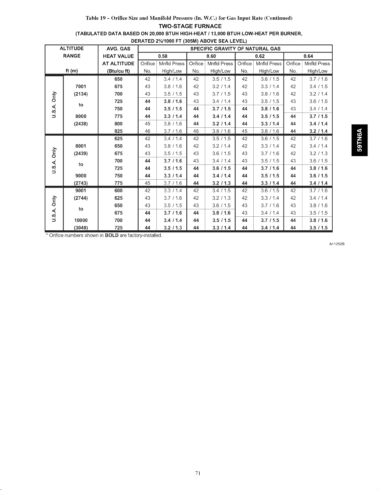
Table 19 - Orifice Size and Manifold Pressure (In. W.C.) for Gas Input Rate (Continued)
(TABULATED DATA BASED ON 20,000 BTUH HIGH-HEAT/13,000 BTUH LOW-HEAT PER BURNER,
DERATED 2°/o/1000 FT (305M) ABOVE SEA LEVEL)
ALTITUDE AVG. GAS
RANGE HEAT VALUE 0.58
AT ALTITUDE Orifice Mnfld Press
ft (m) _ No__ ,,,,,,_h/Low
650
7001 675
--_ (2134) 700
O 725
<' to
8000 775
(2438) 800
8001 650
c (2439) 675
O
<.' to 700
9000 750
__ 775
9001 600
--_ (2744) 625
O 650
<' to 675
10000 700
* Orifice numbers shown in BOLD are factory-installed.
750
825
625
725
42 3.4 / 1.4 42 3.5 / 1.5 42 3.6 / 1.5
43 3.8 / 1.6 42 3.2 / 1.4 42 3.3 / 1.4
43 3.5 / 1.5 43 3.7 / 1.5 43 3.8 / 1.6
44 3.8 / 1.6 43 3.4 / 1.4 43 3.5 / 1.5
44 3.5 / 1.5 44 3.7 / 1.5 44 3.8 / 1.6
44 3.3 / 1.4 44 3.4 / 1.4 44 3.5 / 1.5
45 3.8 / 1.6 44 3.2 / 1.4 44 3.3 / 1.4
46 3.7 / 1.6 46 3.8 / 1.6 45 3.8 / 1.6
42 3.4 / 1.4 42 3.5 / 1.5 42 3.6 / 1.5
43 3.8 / 1.6 42 3.2 / 1.4 42 3.3 / 1.4
43 3.5 / 1.5 43 3.6 / 1.5 43 3.7 / 1.6
44 3.7 / 1.6 43 3.4 / 1.4 43 3.5 / 1.5
44 3.5 / 1.5 44 3.6 / 1.5 44 3.7 / 1.6
44 3.3 / 1.4 44 3.4 / 1.4 44 3.5 / 1.5
45 3.7 / 1.6 44 3.2 / 1.3 44 3.3 / 1.4
42 3.3 / 1.4 42 3.4 / 1.5 42 3.6 / 1.5
43 3.7 / 1.6 42 3.2 / 1.3 42 3.3 / 1.4
43 3.5 / 1.5 43 3.6 / 1.5 43 3.7 / 1.6
44 3.7 / 1.6 44 3.8 / 1.6 43 3.4 / 1.4
44 3.4 / 1.4 44 3.5 / 1.5 44 3.7 / 1.5
TWO-STAGE FURNACE
SPECIFIC GRAVITY OF NATURAL GAS
0.60 0.62
Orifice Mnfld Press Orifice Mnfld Press
No. Hi,h/Low No. Hi,h/Low
3.4 / 1.4
0,64
Orifice Mnfld Press
No. Hi2h/Low
42 3.7 / 1.6
42 3.4 / 1.5
42 3.2 / 1.4
43 3.6 / 1.5
43 3.4 / 1.4
44 3,7 / 1.5
44 3,4 / 1.4
44 3.2 / 1,4
42 3.7 / 1.6
42 3.4 / 1.4
42 3.2 / 1.3
43 3.6 / 1.5
44 3,8 / 1.6
44 3,6 / 1.5
44 3,4 / 1.4
42 3.7 / 1.6
42 3.4 / 1.4
43 3.8 / 1.6
43 3.5 / 1.5
44 3,8 / 1.6
44 3,5 / 1.5
ii
Al1252B
71
Page 72
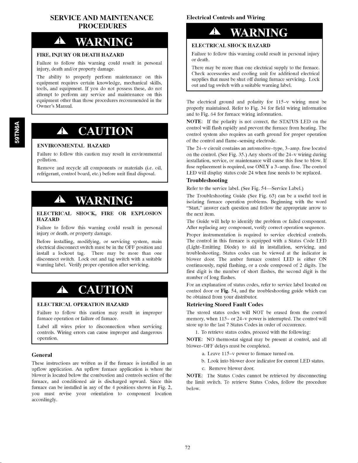
ii
SERVICE AND MAINTENANCE
PROCEDURES
FIRE, INJURY OR DEATH HAZARD
Failure to follow this warning could result in personal
iniury, death and/or property damage.
The ability to properly perform maintenance on this
equipment requires certain knowledge, mechanical skills,
tools, and equipment. If you do not possess these, do not
attempt to perform any service and maintenance on this
equipment other than those procedures recommended in the
Owner's Manual.
ENVIRONMENTAL HAZARD
Failure to follow this caution may result in environmental
pollution.
Remove and recycle all components or materials (i.e. oil,
refrigerant, control board, etc.) before unit final disposal.
ELECTRICAL SHOCK, FIRE OR EXPLOSION
HAZARD
Failure to follow this warning could result in personal
iniury or death, or property damage.
Before installing, modifying, or servicing system, main
electrical disconnect switch must be in the OFF position and
install a lockout tag. There may be more than one
disconnect switch. Lock out and tag switch with a suitaMe
warning label. Verify proper operation after servicing.
ELECTRICAL OPERATION HAZARD
Failure to follow this caution may result in improper
furnace operation or failure of furnace.
Label all wires prior to disconnection when servicing
controls. Wiring errors can cause improper and dangerous
operation.
General
These instructions are written as if the furnace is installed in an
upflow application. An upflow furnace application is where the
blower is located below the combustion and controls section of the
furnace, and conditioned air is discharged upward. Since this
furnace can be installed in any of the 4 positions shown in Fig. 2,
you must revise your orientation to component location
accordingly.
Electrical Controls and Wiring
ELECTRICALSHOCK HAZARD
Failure to follow this warning could result in personal iniury
or death.
There may be more than one electrical supply to the furnace.
Check accessories and cooling unit for additional electrical
supplies that must be shut off during furnace servicing. Lock
out and tag switch with a suitable warning label.
The electrical ground and polarity for 115-v wiring must be
properly maintained. Refer to Fig. 34 for field wiring information
and to Fig. 64 for furnace wiring information.
NOTE: If the polarity is not correct, the STATUS LED on the
control will flash rapidly and prevent the furnace from heating. The
control system also requires an earth ground for proper operation
of the control and flame-sensing electrode.
The 24-v circuit contains an automotive-type, 3-amp. fuse located
on the control. (See Fig. 35.) Any shorts of the 24-v wiring during
installation, service, or maintenance will cause this fuse to blow. If
fuse replacement is required, use ONLY a 3-amp. fuse. The control
LED will display status code 24 when fuse needs to be replaced.
Troubleshooting
Refer to the service label. (See Fig. 54--Service Label.)
The Troubleshooting Guide (See Fig. 63) can be a useful tool in
isolating furnace operation problems. Beginning with the word
"Start," answer each question and follow the appropriate arrow to
the next item.
The Guide will help to identify the problem or failed component.
After replacing any component, verify correct operation sequence.
Proper instrumentation is required to service electrical controls.
The control in this furnace is equipped with a Status Code LED
(Light-Emitting Diode) to aid in installation, servicing, and
troubleshooting. Status codes can be viewed at the indicator in
blower door. The amber furnace control LED is either ON
continuously, rapid flashing, or a code composed of 2 digits. The
first digit is the number of short flashes, the second digit is the
number of long flashes.
For an explanation of status codes, refer to service label located on
control door or Fig. 54, and the troubleshooting guide which can
be obtained from your distributor.
Retrieving Stored Fault Codes
The stored status codes will NOT be erased from the control
memory, when 115- or 24-v power is interrupted. The control will
store up to the last 7 Status Codes in order of occurrence.
1. To retrieve status codes, proceed with the following:
NOTE: NO thermostat signal may be present at control, and all
blower-OFF delays must be completed.
a. Leave l15-v power to furnace turned on.
b. Look into blower door indicator for current LED status.
c. Remove blower door.
NOTE: The Status Codes cannot be retrieved by disconnecting
the limit switch. To retrieve Status Codes, follow the procedure
below.
72
Page 73
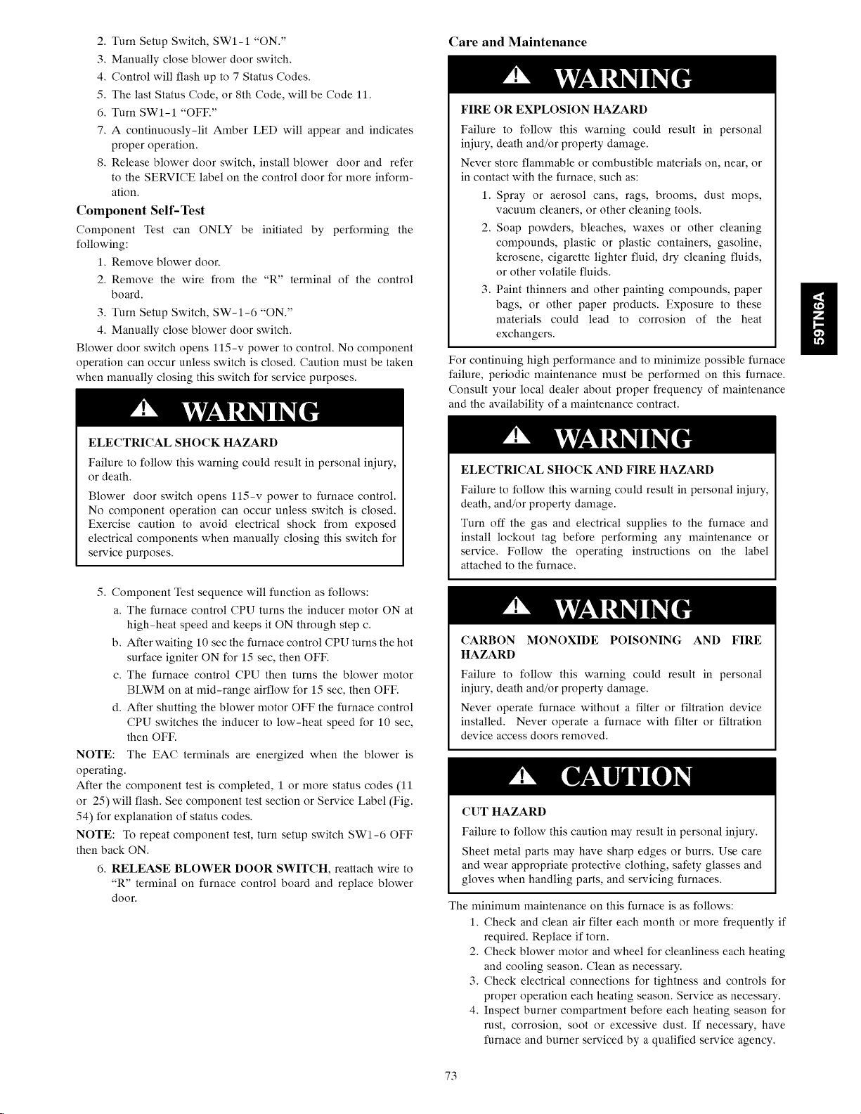
2.TurnSetupSwitch,SWI-1"ON."
3.Manuallycloseblowerdoorswitch.
4.Controlwillflashupto7StatusCodes.
5. The last Status Code, or 8th Code, will be Code 11.
6. Turn SWI-1 "OFF."
7. A continuously-lit Amber LED will appear and indicates
proper operation.
8. Release blower door switch, install blower door and refer
to the SERVICE label on the control door for more inform-
ation.
Component Self-Test
Component Test can ONLY be initiated by performing the
following:
1. Remove blower door.
2. Remove the wire from the "R" terminal of the control
board.
3. Turn Setup Switch, SW-1-6 "ON."
4. Manually close blower door switch.
Blower door switch opens 115-v power to control. No component
operation can occur unless switch is closed. Caution must be taken
when manually closing this switch for service purposes.
ELECTRICALSHOCK HAZARD
Failure to follow this warning could result in personal iniury,
or death.
Blower door switch opens 115-v power to furnace control.
No component operation can occur unless switch is closed.
Exercise caution to avoid electrical shock from exposed
electrical components when manually closing this switch for
service purposes.
Care and Maintenance
FIRE OR EXPLOSION HAZARD
Failure to follow this warning could result in personal
iniury, death and/or property damage.
Never store flammable or combustible materials on, near, or
in contact with the furnace, such as:
1. Spray or aerosol cans, rags, brooms, dust mops,
vacuum cleaners, or other cleaning tools.
2. Soap powders, bleaches, waxes or other cleaning
compounds, plastic or plastic containers, gasoline,
kerosene, cigarette lighter fluid, dry cleaning fluids,
or other volatile fluids.
3. Paint thinners and other painting compounds, paper
bags, or other paper products. Exposure to these
materials could lead to corrosion of the heat
exchangers.
For continuing high performance and to minimize possible furnace
failure, periodic maintenance must be performed on this furnace.
Consult your local dealer about proper frequency of maintenance
and the availability of a maintenance contract.
ELECTRICAL SHOCK AND FIRE HAZARD
Failure to follow this warning could result in personal iniury,
death, and/or property damage.
Turn off the gas and electrical supplies to the furnace and
install lockout tag before performing any maintenance or
service. Follow the operating instructions on the label
attached to the furnace.
H
5. Component Test sequence will function as follows:
a. The furnace control CPU turns the inducer motor ON at
high-heat speed and keeps it ON through step c.
b. After waiting 10 sec the furnace control CPU turns the hot
surface igniter ON for 15 sec, then OFF.
c. The furnace control CPU then turns the blower motor
BLWM on at mid-range airflow for 15 sec, then OFF.
d. After shutting the blower motor OFF the furnace control
CPU switches the inducer to low-heat speed for 10 sec,
then OFF.
NOTE: The EAC terminals are energized when the blower is
operating.
After the component test is completed, 1 or more status codes (11
or 25) will flash. See component test section or Service Label (Fig.
54) for explanation of status codes.
NOTE: To repeat component test, turn setup switch SWI-6 OFF
then back ON.
6. RELEASE BLOWER DOOR SWITCH, reattach wire to
"R" terminal on furnace control board and replace blower
door.
CARBON MONOXIDE POISONING AND FIRE
HAZARD
Failure to follow this warning could result in personal
iniury, death and/or property damage.
Never operate furnace without a filter or filtration device
installed. Never operate a furnace with filter or filtration
device access doors removed.
CUT HAZARD
Failure to follow this caution may result in personal iniury.
Sheet metal parts may have sharp edges or burrs. Use care
and wear appropriate protective clothing, safety glasses and
gloves when handling parts, and servicing furnaces.
The minimum maintenance on this furnace is as follows:
1. Check and clean air filter each month or more frequently if
required. Replace if torn.
2. Check blower motor and wheel for cleanliness each heating
and cooling season. Clean as necessary.
3. Check electrical connections for tightness and controls for
proper operation each heating season. Service as necessary.
4. Inspect burner compartment before each heating season for
rust, corrosion, soot or excessive dust. If necessary, have
furnace and burner serviced by a qualified service agency.
73
Page 74

ii
5. Inspect the vent pipe/vent system before each heating sea-
son for water leakage, sagging pipes or broken firings.
Have vent pipes/vent system serviced by a qualified service
agency.
6. Inspect any accessories attached to the furnace such as a hu-
midifier or electronic air cleaner. Perform any service or
maintenance to the accessories as recommended in the ac-
cessory instructions.
Cleaning and/or Replacing Air Filter
The air filter type may vary depending on the application or
orientation. The filter is external to the furnace casing. There are no
provisions for an internal filter with this furnace. See "Filter
Arrangement" under the "Installation" section of this manual.
CARBON MONOXIDE POISONING AND FIRE
HAZARD
Failure to follow this warning could result in personal
injury, death and/or property damage.
Never operate furnace without a filter or filtration device
installed. Never operate a furnace with filter or filtration
device access doors removed.
NOTE: If the filter has an airflow direction arrow, the arrow must
point toward the blower.
To clean or replace filters, proceed as follows:
ELECTRICAL SHOCK, FIRE OR EXPLOSION
HAZARD
Failure to follow this warning could result in personal
injury or death, or property damage.
Before installing, modifying, or servicing system, main
electrical disconnect switch must be in the OFF position and
install a lockout tag. There may be more than one
disconnect switch. Lock out and tag switch with a suitable
warning label. Verify proper operation after servicing.
1. Turn off electrical supply to furnace.
2. Remove filter cabinet door.
3. Slide filter out of cabinet.
4. If equipped with permanent, washable filter, clean filter by
spraying cold tap water through filter in opposite direction
of airflow. Rinse filter and let dry. Oiling or coating of the
filter is not recommended.
5. If equipped with factory specified disposable media filter,
replace only with a factory specified media filter of the same
size.
6. Slide filter into cabinet.
7. Replace filter cabinet door.
8. Turn on electrical supply to furnace.
Blower Motor and Wheel Maintenance
To ensure long life, economy, and high efficiency, clean
accumulated dirt and grease from blower wheel and motor
annually.
The inducer and blower motors are pre-lubricated and require no
additional lubrication. These motors can be identified by the
absence of oil ports on each end of the motor.
The following items should be performed by a qualified service
technician. Clean blower motor and wheel as follows:
1. Turn off electrical supply to furnace.
2. Remove blower door.
3. All factory wires can be left connected, but field thermostat
and accessory wiring may need to be disconnected depend-
ing on their length and routing.
4. If the vent and combustion air pipe passes through the
blower compartment, it will be necessary to remove the
pipes from the blower compartment.
Disconnect the vent and combustion air pipe by:
a. Loosen the clamps on the vent couplings and combustion
air pipe external to the furnace.
b. Separate the pipes from the couplings and move them
aside.
c. Loosen the clamps on the vent couplings and combustion
air pipe located on the blower shelf.
d. Separate the pipes from the blower compartment and set
aside.
e. Remove the couplings from the pipe adapters and set aside.
f. After servicing the blower, reverse steps a through e.
g. Tighten all clamps 15 lb -in.
See Fig. 61 For Steps 5 through 14.
5. Remove screws securing blower assembly to blower shelf
and slide blower assembly out of furnace. Detach ground
wire and disconnect blower motor harness plugs from
blower motor.
NOTE: Blower wheel is fragile. Use care.
6. Clean blower wheel and motor by using a vacuum with soft
brush attachment. Be careful not to disturb balance weights
(clips) on blower wheel vanes. Do not bend wheel or blades
as balance will be affected.
7. If greasy residue is present on blower wheel, remove wheel
from the blower housing and wash it with an appropriate
degreaser. To remove wheel:
a. Mark blower wheel location on shaft before disassembly
to ensure proper reassembly.
b. Loosen setscrew holding blower wheel on motor shaft.
NOTE: Mark blower mounting arms and blower housing so each
arm is positioned at the same hole location during reassembly.
c. Mark blower wheel orientation and cutoff plate location to
ensure proper reassembly.
d. Remove screws securing cutoff plate and remove cutoff
plate from housing.
e. Remove bolts holding motor mounts to blower housing
and slide motor and mounts out of housing.
f. Remove blower wheel from housing.
g. Clean wheel per instructions on degreaser cleaner. Do not
get degreaser in motor.
8. Reassemble motor and blower wheel by reversing items 7b
through 7f. Ensure wheel is positioned for proper rotation.
9. Torque motor mounting bolts to 40 +/- 10 lb-in, when reas-
sembling.
10. Torque blower wheel set screw to 160 +/- 20 lb-in, when
reassembling.
11. Verify that blower wheel is centered in blower housing and
set screw contacts the flat portion of the motor shaft. Loosen
set screw on blower wheel and reposition if necessary.
12. Spin the blower wheel by hand to verify that the wheel does
not rub on the housing.
13. Reinstall blower assembly in furnace.
14. Reinstall 2 screws securing blower assembly to blower
deck.
15. Reconnect blower leads to furnace control. Refer to furnace
wiring diagram, and connect thermostat leads if previously
disconnected.
NOTE: Be sure to attach ground wire and reconnect blower
harness plugs to blower motor.
74
Page 75

ELECTRICALOPERATIONHAZARD
Failuretofollowthiswarningcouldresultinpersonalinjury
ordeath.
Blowerdoorswitchopens115-vpowerto control.No
componentoperationcanoccurunlessswitchis closed.
Cautionmustbetakenwhenmanuallyclosingthisswitchfor
servicepurposes.
16.Downfloworhorizontalfurnaceswithventpipethrough
furnaceonly:
a.Installandconnectshortpieceofventpipeinsidefurnace
toexistingvent.
b.Connectventconnectortoventelbow.
17.Turnonelectricalsupply.Manuallycloseblowerdoor
switch.Useapieceoftapetoholdswitchclosed.Checkfor
properrotationandspeedchangesbetweenheatingand
coolingbyjumperingRtoGandRtoY/Y2onfurnace
controlthermostatterminals.If outdoortemperatureisbe-
low70°F,turnoffcircuitbreakertooutdoorunitbefore
runningfurnaceinthecoolingcycle.Turnoutdoorcircuit
breakeronaftercompletingcoolingcycle.(SeeFig.35.)
NOTE:If R-W/Wlthermostatterminalsarejumperedatthetime
blowerdoorswitchisclosed,blowerwillrunfor90secbefore
beginningaheatingcycle.
a.Performcomponentself-testasshownatthebottomofthe
SERVICElabel,locatedonthecontroldoor.
b.Verifyblowerisrotatinginthecorrectdirection
18.If furnaceis operatingproperly,RELEASEBLOWER
DOORSWITCH.Removeanyjumpersorreconnectany
disconnectedthermostatleads.Replaceblowerdoor.
19.Turnongassupplyandcyclefurnacethroughonecomplete
heatingcycle.Verifythefurnacetemperatureriseasshown
inAdjustmentsSection.Adjusttemperatureriseasshownin
AdjustmentsSection.
CleaningBurnersandFlameSensor
Thefollowingitemsmustbeperformedbyaqualifiedservice
technician.If theburnersdevelopanaccumulationoflightdirtor
dust,theymaybecleanedbyusingthefollowingprocedure:
NOTE:Useaback-upwrenchonthegasvalvetopreventthe
valvefromrotatingonthemanifoldordamagingthemountingto
theburnerassembly.
ELECTRICALSHOCKANDFIREHAZARD
Failuretofollowthiswarningcouldresultinpersonaliniury,
death,and/orpropertydamage.
Turnoffthegasandelectricalsuppliestothefurnaceand
installlockouttagbeforeperforminganymaintenanceor
service.Followtheoperatinginstructionsonthelabel
attachedtothefurnace.
RefertoFig.62.
1.Disconnectpoweratexternaldisconnect,fuseorcircuit
breaker.
2.Turnoffgasatexternalshut-offorgasmeter.
3.Removecontroldoorandsetaside.
4.TurnelectricswitchongasvalvetoOFF.
5.Disconnectthegaspipefromgasvalveandremovepipe
fromthefurnacecasing.
6.Removeindividualwiresfromterminalsongasvalve.
7.DisconnectHotSurfaceIgniter(HSI)wiresfromHSI.
8.DisconnectFlameSensorwirefromFlameSensor.
9.Supportthemanifoldandremovethe4screwsthatsecure
themanifoldassemblytotheburnerassemblyandsetaside.
Notethelocationofthegreen/yellowwireandgroundter-
minal.
10.Inspecttheorificesinthemanifoldassemblyforblockages
orobstructions.Removeorificeandcleanorreplaceorifice.
11.Removethefourscrewsthatattachthetopplateofthecas-
ingtothefurnace.
12.Raisetopplateupslightlyandpropitupwithasmallpiece
ofwoodorfoldedcardboard.
13.Supporttheburnerassemblyandremovethescrewsthatat-
tachtheburnerassemblytotheheatexchangercellpanel.
14.Removewiresfrombothrolloutswitches.
15.Slideone-pieceburneroutofslotsonsidesofburneras-
sembly.
16.Removetheflamesensorfromtheburnerassembly.
17.(Optional)RemovetheHotSurfaceIgniter(HSI)and
bracketfromtheburnerassembly.
18.Checkigniterresistance.Nominalresistanceis40to70
ohmsatroomtemperatureandisstableoverthelifeofthe
igniter.
19.Cleanburnerwithabrushandavacuum.
20.Cleantheflamesensorwithfinesteelwool(0000grade).
Donotusesandpaperoremerycloth.
Toreinstallburnerassembly:
1.InstalltheHotSurfaceIgniter(HSI)andbracketinburner
assembly.
2.Installflamesensoronburner.
3.Aligntheedgesoftheone-pieceburnerwiththeslotsinthe
burnerassemblyandslidetheburnersforwarduntiltheyare
fullyseatedintheburnerassembly.
4.Aligntheorificesinthemanifoldassemblywiththesupport
ringsontheendoftheburner.
5.Inserttheorificesinthesupportringsoftheburners.
NOTE:Ifmanifolddoesnotfitflushagainsttheburner,donot
forcethemanifoldontheburnerassembly.Theburnersarenot
fullyseatedforwardintheburnerassembly.Removethemanifold
andcheckburnerpositioningintheburnerassemblyassembly
beforere-installingthemanifold.
6.Attachthegreen/yellowwireandgroundterminaltooneof
themanifoldmountingscrews.
7.Installtheremainingmanifoldmountingscrews.
8.Checktheigniteralignment.SeeFig.56,58and62.
9.Attachthewirestotheroll-outswitches.
10.Aligntheburnerassemblywiththeopeningsintheprimary
cellinletpanelandattachtheburnerassemblytothecell
panel.
11.Connectthewirefortheflamesensor.
12.ConnectthewirefortheHotSurfaceIgniter.
NOTE:Usepropane-resistantpipedopetopreventleaks.Donot
useTeflontape.
13.Installthegaspipetothegasvalve.
FIREOR'EXPLOSIONHAZARD
Failuretofollowthiswarningcouldresultinpersonal
iniury,death,and/orpropertydamage.
Neverpurgeagaslineintoacombustionchamber.Never
testforgasleakswithanopenflame.Useacommercially
availablesoapsolutionmadespecificallyforthedetection
ofleakstocheckallconnections.Afireorexplosionmay
resultcausingpropertydamage,personaliniuryorlossof
line.
14.Checkforgasleakswithacommerciallyavailablesoap
solutionmadespecificallyforthedetectionofleaks.
ii
75
Page 76

15. Turn gas on at electric switch on gas valve and at external
shut-off or meter
16. Turn power on at external disconnect, fuse or circuit break-
er.
17. Run the furnace through two complete heating cycles to
check for proper operation
18. Install control door when complete.
Servicing Hot Surface Igniter
The igniter does NOT require annual inspection. Check igniter
resistance before removal. Refer to Fig. 56, 58 and 62.
1. Turn off gas and electrical supplies to furnace.
2. Remove control door.
3. Disconnect igniter wire connection.
4. Check igniter resistance. Igniter resistance is affected by
temperature. Only check resistance when the igniter is at
room temperature.
a. Using an ohm meter, check resistance across both igniter
leads in connector.
b. Cold reading should be between 40 ohms and 70 ohms.
5. Remove igniter assembly.
a. Using a 1/4-in. driver, remove the two screws securing the
igniter mounting bracket to the burner assembly (See Fig.
62 .)
b. Carefully withdraw the igniter and bracket assembly
through the front of the burner assembly without striking
the igniter on surrounding parts.
c. Inspect igniter for signs of damage or failure.
d. If replacement is required, remove the screw that secures
the igniter on igniter bracket and remove the igniter.
6. To replace igniter and bracket assembly, reverse items 5a
through 5d.
7. Reconnect igniter harness to the igniter, dressing the igniter
wires to ensure there is no tension on the igniter itself. (See
Fig. 62.)
8. Turn on gas and electrical supplies to furnace.
9. Verify igniter operation by initiating control board self-test
feature or by cycling thermostat.
10. Replace control door.
Flushing Collector Box and Drainage System
ELECTRICAL SHOCK AND FIRE HAZARD
Failure to follow this warning could result in personal injury,
death, and/or property damage.
Turn off the gas and electrical supplies to the furnace and
install lockout tag before performing any maintenance or
service. Follow the operating instructions on the label
attached to the furnace.
1. Turn off gas and electrical supplies to furnace.
2. Remove control door.
3. Disconnect pressure switch tube from pressure switch port.
NOTE: Ensure the pressure switch tube disconnected from the
pressure switch is higher than the collector box opening or water
will flow out of tube.
4. Remove the collector box plug from the top port on the up-
per corner of the collector box. (See Fig. 59)
5. Attach a flmnel with a flexible tube to port on the collector
box.
6. Flush inside of collector box with water until discharge
water from condensate trap is clean and runs freely.
7. Repeat steps 4 thru 6 with middle plug on upper corner of
collector box.
8. Remove the pressure switch tube from the collector box.
NOTE: Do NOT blow into tube with tube connected to the
pressure switch.
9. Clean pressure switch port on collect box with a small wire.
Shake any water out of pressure switch tube.
10. Reconnect tube to pressure switch and pressure switch port.
11. Remove the relief tube from the port on the collector box
and the trap.
12. Clean the relief port on collect box and the trap with a small
wire. Shake any water out of the tube.
13. Reconnect relief tube to trap and collector box ports.
Cleaning Condensate Drain and Trap
NOTE: If the condensate trap is removed, a new gasket between
the trap and collector box is required. Verify a condensate trap
gasket is included in the service kit or obtain one from your local
distributor.
1. Disconnect power at external disconnect, fuse or circuit
breaker.
2. Turn off gas at external shut-off or gas meter.
3. Remove control door and set aside.
4. Turn electric switch on gas valve to OFF.
5. Disconnect external drain from condensate drain elbow or
drain extension pipe inside the furnace and set aside.
6. Disconnect the condensate trap relief hose from collector
box port and condensate trap.
NOTE: If condensate has a heat pad attached to the trap, trace the
wires for the pad back to the connection point and disconnect the
wires for the heat pad.
7. Remove the screw that secures the condensate trap to the
collector box, remove the trap and set aside.
8. Remove the trap gasket from the collector box if it did not
come off when the trap was removed.
9. Discard the old trap gasket.
10. Rinse condensate trap in warm water until trap is clean.
11. Flush condensate drain lines with warm water. Remember
to check and clean the relief port on the collector box.
12. Shake trap dry.
13. Clean port on collector box with a small wire.
To re-install Condensate Drain and Trap:
1. Remove adhesive backing from condensate trap gasket
2. Install gasket on collector box
3. Align the condensate trap with the drain opening on the col-
lector box and secure the trap with the screw
4. Attach the relief hose to the relief port on the condensate
trap and collector box.
5. Secure tubing to prevent any sags or traps in the tubing.
6. Connect condensate drain elbow or drain extension elbow
to the condensate trap
7. Connect the leads of the condensate heat pad (if used)
8. Connect external drain piping to the condensate drain elbow
or drain extension pipe.
9. Turn gas on at electric switch on gas valve and at external
shut-off or meter
10. Turn power on at external disconnect, fuse or circuit break-
er.
11. Run the furnace through two complete heating cycles to
check for proper operation
12. Install control door when complete.
Checking Heat Pad Operation (If Applicable)
In applications where the ambient temperature around the furnace
is 32°F or lower, freeze protection measures are required, If this
application is where heat tape has been applied, check to ensure it
will operate when low temperatures are present,
76
Page 77

NOTE:TheHeatPad,whenused,shouldbewrappedaroundthe
condensatedraintrap.Thereisnoneedtouseheattapewithinthe
furnacecasing.Mostheattapesaretemperatureactivated,anditis
notpracticaltoverifytheactualheatingofthetape.Checkthe
following:
1.Checkforsignsofphysicaldamagetoheattapesuchas
nicks,cuts,abrasions,gnawingbyanimals,etc.
2.Checkfordiscoloredheattapeinsulation.If anydamageor
discoloredinsulationisevident,replaceheattape.
3.Checkthatheattapepowersupplycircuitison.
Cleaning Heat Exchangers
The following items must be performed by a qualified service
technician.
Primary Heat Exchangers
If the heat exchangers get an accumulation of light dirt or dust on
the inside, they may be cleaned by the following procedure:
NOTE: If the heat exchangers get a heavy accumulation of soot
and carbon, both the primary and secondary heat exchangers
should be replaced rather than trying to clean them thoroughly due
to their intricate design. A build-up of soot and carbon indicates
that a problem exists which needs to be corrected, such as improper
adjustment of manifold pressure, insufficient or poor quality
combustion air, improper vent termination, incorrect size or
damaged manifold orifice(s), improper gas, or a restricted heat
exchanger (primary or secondary). Action must be taken to correct
the problem.
1. Turn off gas and electrical supplies to furnace.
ELECTRICAL SHOCK, FIRE OR EXPLOSION
HAZARD
Failure to follow this warning could result in personal
injury or death, or property damage.
Before installing, modifying, or servicing system, main
electrical disconnect switch must be in the OFF position and
install a lockout tag. There may be more than one
disconnect switch. Lock out and tag switch with a suitable
warning label. Verify proper operation after servicing.
ELECTRICAL SHOCK AND FIRE HAZARD
Failure to follow this warning could result in personal injury,
death, and/or property damage.
Turn off the gas and electrical supplies to the furnace and
install lockout tag before performing any maintenance or
service. Follow the operating instructions on the label
attached to the furnace.
7. Clean heat exchanger openings with a vacuum and a soft
brush. (See Fig. 60.)
NOTE: After cleaning, inspect the heat exchangers to ensure they
are free of all foreign objects that may restrict flow of combustion
products.
8. Reverse items 6 through 1 for reassembly.
9. Refer to furnace wiring diagram and reconnect wires to
flame rollout switch, gas valve, igniter, and flame sensor.
10. Turn on gas and electrical supplies to furnace.
11. Check furnace operation through 2 complete heat operating
cycles. Look at burners. Burner flames should be clear blue,
almost transparent. (See Fig. 570
12. Check for gas leaks.
FIRE OR'EXPLOSION HAZARD
Failure to follow this warning could result in personal
injury, death, and/or property damage.
Never purge a gas line into a combustion chamber. Never
test for gas leaks with an open flame. Use a commercially
available soap solution made specifically for the detection
of leaks to check all connections. A fire or explosion may
result causing property damage, personal injury or loss of
line.
13. Replace main furnace door.
Secondary Heat Exchangers
The condensing side (inside) of the secondary heat exchanger
CANNOT be serviced or inspected without complete removal of
the heat exchanger assembly. Detailed information on heat
exchanger removal can be obtained from your Distributor.
WINTERIZATION
[]NIT AND PROPERTY DAMAGE HAZARD
Failure to follow this caution may result in unit component or
property damage.
If the furnace is installed in an unconditioned space where the
ambient temperatures may be 32 ° F (0 ° C) or lower, freeze
protection measures must be taken to prevent minor property
or product damage.
Since the furnace uses a condensing heat exchanger, some water
will accumulate in the unit as a result of the heat transfer process.
Therefore, once it has been operated, it cannot be turned off and
left off for an extended period of time when temperatures will
reach 32°F (0°C) or lower unless winterized. Follow these
)rocedures to winterize your furnace:
H
2. Remove control door.
3. Disconnect wires or connectors to flame rollout switch, gas
valve, igniter, and flame sensor.
4. Using backup wrench, disconnect gas supply pipe from fur-
nace gas control valve.
5. Remove two screws attaching top filler plate and rotate up-
wards to gain access to screws attaching burner assembly to
cell panel.
6. Remove screws attaching burner assembly to cell panel.
(See Fig. 62.)
NOTE: Burner cover, manifold, gas valve, and burner assembly
should be removed as one assembly.
[]NIT COMPONENT DAMAGE HAZARD
Failure to follow this caution may result in damage to the
furnace and other property damage.
Do not use ethylene glycol (automotive antifreeze coolant or
equivalent). Failure of plastic components may occur.
1. Obtain propylene glycol (RV/swimming pool antifreeze or
equivalent).
2. Turn off gas and electrical supplies to your furnace.
3. Remove furnace control door.
77
Page 78

ii
4. Remove the top unused rubber plug from the port on the
collector box opposite the condensate trap. See Fig. 59.
5. Connect a field supplied 3/8-in. (9.5-ram) ID tube to the
open port on the collector box
6. Insert a field supplied funnel into the tube.
7. Pour 1 quart of anti-freeze solution into the funnel/tube.
Antifreeze should run through the inducer housing, overfill
condensate trap and flow to an open drain.
8. Replace the rubber plug in the port on the collector box.
9. Remove the nfiddle unused rubber plug from the port on the
collector box opposite the condensate trap. See Fig. 59.
10. Repeat Steps 5 through 8.
11. If a condensate pump is used, check with pump
manufacturer to verify pump is safe for use with antifreeze
used. Allow pump to start and pump anti-freeze to open
drain.
12. Replace main door.
13. When furnace is re-started, flush condensate pump with
clear water to check for proper operation before re-starting
furnace.
14. Propylene glycol need not be removed before re-starting
furnace.
3/8-in.
9.6 mm
3/16-in.
4.6 mm
+0.8
2.5 mm_1.5
Al1620
Fig. 58 - Igniter Position - Side View
t Iv " to
m
(64.4)
Fig. 56 - Igniter Position - Top View
Burner Flame
/- Burner
_2
Al1405
o
o
Al1392
Fig. 59 - Priming Condensate Trap
Fig. 57 - Burner Flame
Al1461
Al1273
Fig. 60 - Cleaning Heat Exchanger Cell
78
Page 79

MOTORSHAFT
SET - /
"- MOTOR WHEEL HUB
SCREW LOCATION
BLO HSG ASSY
BRACKET
BRACKET
ENGAGEMENT
DETAIL A
/
SEE DETAILA _X .
CUTOFF, BLOWER
BRACKET_
CAPACITOR
OR POWER CHOKE
(WHEN USED)
WHEEL, BLOWER
J
-- BLOWER HSG ASSY
%
MOTOR, BLOWER
A11584
Fig. 61 - Blower Assembly
79
Page 80

BURNER SUPT ASSY
BURNER ASSY
IGNITER
BRACKET, IGNITER
FLAME ROLLOUT
SWITCH
'__.,,,, FLAME SENSOR
(BELOW BURNER)
Fig. 62 - Burner Assembly
A11403
80
Page 81

SEQUENCE OF OPERATION
NOTE: Furnace control must be grounded for proper operation or
else control will lock out. Control is grounded through
green/yellow wire routed to gas valve and burner box screw. Using
the schematic diagram in Fig. 64, follow the sequence of operation
through the different modes. Read and follow the wiring diagram
very carefully.
NOTE: If a power interruption occurs during a call for heat
(W/Wl or W/Wl-and-W2), the control will start a 90-sec
blower-only ON period two sec after power is restored, if the
thermostat is still calling for gas heating. The amber LED light will
flash code 12 during the 90-sec period, after which the LED will
be ON continuous, as long as no faults are detected. After the
90-sec period, the furnace will respond to the thermostat normally.
The blower door must be installed for power to be conducted
through the blower door interlock switch ILK to the furnace
control CPU, transformer TRAN, inducer motor IDM, blower
motor BLWM, hot-surface igniter HSI, and gas valve GV.
1. Two-Stage Heating (Adaptive Mode) with Single-Stage
Thermostat
See Fig. 35 and 36 for thermostat connections
NOTE: The low-heat only switch SWI-2 selects either the
low-heat only operation mode when ON, (see item 2. below) or
the adaptive heating mode when OFF in response to a call for heat.
(See Fig. 55.) When the W2 thermostat terminal is energized it will
always cause high-heat operation when the R-to-W circuit is
closed, regardless of the setting of the low-heat only switch. This
furnace can operate as a two-stage furnace with a single-stage
thermostat because the furnace control CPU includes a
programmed adaptive sequence of controlled operation, which
selects low-heat or high-heat operation. This selection is based
upon the stored history of the length of previous gas-heating
periods of the single-stage thermostat.
The furnace will start up in either low- or high-heat. If the furnace
starts up in low-heat, the control CPU determines the low-heat
on-time (from 0 to 16 minutes) which is permitted before
switching to high-heat.
If the power is interrupted, the stored history is erased and the
control CPU will select low-heat for up to 16 minutes and then
switch to high-heat, as long as the thermostat continues to call for
heat. Subsequent selection is based on stored history of the
thermostat cycle times.
The wall thermostat "calls for heat", closing the R-to-W circuit.
The furnace control performs a self-check, verifies the low-heat
and high-heat pressure switch contacts LPS and HPS are open, and
starts the inducer motor IDM in high-speed.
a. Inducer Prepurge Period
(1.) If the furnace control CPU selects low-heat opera-
tion the inducer motor IDM comes up to speed, the
low-heat pressure switch LPS closes, and the fur-
nace control CPU begins a 15-sec prepurge period.
If the low-heat pressure switch LPS fails to remain
closed the inducer motor IDM will remain running
at high-speed. After the low-heat pressure switch
re-closes the furnace control CPU will begin a
15-sec prepurge period, and continue to run the
inducer motor IDM at high-speed.
(20 If the furnace control CPU selects high-heat opera-
tion, the inducer motor IDM remains running at
high-speed, and the high-heat pressure switch re-
lay HPSR is de-energized to close the NC contact.
When sufficient pressure is available the high-heat
pressure switch HPS closes, and the high-heat gas
valve solenoid GV-HI is energized. The furnace
control CPU begins a 15-sec prepurge period after
the low-heat pressure switch LPS closes. If the
high-heat pressure switch HPS fails to close and
the low-heat pressure switch LPS closes, the fur-
nace will operate at low-heat gas flow rate until the
high-heat pressure switch closes for a maximum of
2 minutes after ignition.
b. Igniter Warm-Up -At the end of the prepurge period, the
Hot-Surface Igniter HSI is energized for a 17-sec igniter
warm-up period.
c. Trial-For-Ignition Sequence -When the igniter warm-
up period is completed the main gas valve relay contact
GVR closes to energize the gas valve solenoid GV-M. The
gas valve solenoid GV-M permits gas flow to the burners
where it is ignited by the HSI. Five sec after the GVR
closes, a 2-sec flame proving period begins. The HSI ig-
niter will remain energized until the flame is sensed or until
the 2-sec flame proving period begins. If the furnace con-
trol CPU selects high-heat operation, the high-heat gas
valve solenoid GV-HI is also energized.
d. Flame-Proving - When the burner flame is proved at the
flame-proving sensor electrode FSE, the inducer motor
IDM switches to low-speed unless the furnace is operating
in high-heat, and the furnace control CPU begins the
blower-ON delay period and continues to hold the gas
valve GV-M open. If the burner flame is not proved within
two sec, the control CPU will close the gas valve GV-M,
and the control CPU will repeat the ignition sequence for
up to three more Trials-For-Ignition before going to Igni-
tion-Lockout. Lockout will be reset automatically after
three hours, or by momentarily interrupting 115 v ac power
to the furnace, or by interrupting 24 vac power at SECI or
SEC2 to the furnace control CPU (not at W/WI, G, R, etc.).
If flame is proved when flame should not be present, the
furnace control CPU will lock out of Gas-Heating mode
and operate the inducer motor IDM on high speed until
flame is no longer proved.
e. Blower-On delay - If the burner flame is proven the
blower-ON delays for low-heat and high-heat are as fol-
lows:
Low-heat - 45 sec after the gas valve GV-M is opened
the blower motor BLWM is turned ON at low-heat airflow.
High-heat - 25 sec after the gas valve GV-M is opened
the BLWM is turned ON at high-heat airflow. Simultan-
eously, the humidifier terminal HUM and electronic air
cleaner terminal EAC-1 are energized and remain ener-
gized throughout the heating cycle.
f. Switching from Low- to High-Heat - If the furnace con-
trol CPU switches from low-heat to high-heat, the furnace
control CPU will switch the inducer motor IDM speed
from low to high. The high-heat pressure switch relay
HPSR is de-energized to close the NC contact. When suffi-
cient pressure is available the high-heat pressure switch
HPS closes, and the high-heat gas valve solenoid GV-HI
is energized. The blower motor BLWM will transition to
high-heat airflow five sec after the furnace control CPU
switches from low-heat to high-heat.
g. Switching from High- to Low-Heat -The furnace con-
trol CPU will not switch from high-heat to low-heat while
the thermostat R-to-W circuit is closed when using a
single-stage thermostat.
h. Blower-OffDelay -When the thermostat is satisfied, the
R to W circuit is opened, de-energizing the gas valve GV-
M, stopping gas flow to the burners, and de-energizing the
humidifier terminal HUM. The inducer motor IDM will re-
main energized for a 15-sec post-purge period. The
blower motor BLWM and air cleaner terminal EAC- 1 will
remain energized at low-heat airflow or transition to low-
heat airflow for 90, 120, 150, or 180 sec (depending on se-
81
ii
Page 82
lection at blower-OFF delay switches). The furnace con-
trol CPU is factory-set for a 120-sec blower-OFF delay.
2. Two-Stage Thermostat and Two-Stage Heating
See Fig. 35 and 36 for thermostat connections.
NOTE: In this mode the low-heat only switch SWI-2 must be
ON to select the low-heat only operation mode in response to
closing the thermostat R-to-Wl circuit. Closing the thermostat
R-to- Wl-and-W2 circuits always causes high-heat operation,
regardless of the setting of the low-heat only switch.
The wall thermostat "calls for heat", closing the R-to-Wl circuit
for low-heat or closing the R-to-Wl-and-W2 circuits for
high-heat. The furnace control performs a self-check, verifies the
low-heat and high-heat pressure switch contacts LPS and HPS are
open, and starts the inducer motor IDM in high-speed.
The start up and shut down functions and delays described in item
1. above apply to the 2-stage heating mode as well, except for
switching from low- to high-Heat and vice versa.
a. Switching from Low- to High-Heat - If the thermostat
ii
R-to-W1 circuit is closed and the R-to-W2 circuit closes,
the furnace control CPU will switch the inducer motor
IDM speed from low to high. The high-heat pressure
switch relay HPSR is de-energized to close the NC contact.
When sufficient pressure is available the high-heat pres-
sure switch HPS closes, and the high-heat gas valve solen-
oid GV-HI is energized. The blower motor BLWM will
transition to high-heat airflow five sec after the R-to-W2
circuit closes.
b. Switching from High- to Low-Heat -If the thermostat
R-to- W2 circuit opens, and the R-to-W1 circuit remains
closed, the furnace control CPU will switch the inducer
motor IDM speed from high to low. The high-heat pres-
sure switch relay HPSR is energized to open the NC contact
and de-energize the high-heat gas valve solenoid GV-HI.
When the inducer motor IDM reduces pressure suffi-
ciently, the high-heat pressure switch HPS will open. The
gas valve solenoid GV-M will remain energized as long
as the low-heat pressure switch LPS remains closed. The
blower motor BLWM will transition to low-heat airflow
five sec after the R-to-W2 circuit opens.
3. Cooling mode
The thermostat "calls for cooling".
a. Single-Speed Cooling-
See Fig. 35 and 36 for thermostat connections
The thermostat closes the R-to-G-and-Y circuits. The
R-to- Y circuit starts the outdoor unit, and the R-to-
G-and-Y/Y2 circuits start the furnace blower motor
BLWM on cooling airflow. Cooling airflow is based on the
A/C selection shown in Fig. 55. The electronic air cleaner
terminal EAC-I is energized with 115 vac when the
blower motor BLWM is operating.
When the thermostat is satisfied, the R-to-G-and-Y cir-
cuits are opened. The outdoor unit will stop, and the fur-
nace blower motor BLWM will continue operating at cool-
ing airflow for an additional 90 sec. Jumper Y/Y2 to
DHUM to reduce the cooling off-delay to 5 sec. (See Fig.
35.)
b. Single-Stage Thermostat and Two-Speed Cooling
(Adaptive Mode) -
See Fig. 35 and 36 for thermostat connections.
This furnace can operate a two-speed cooling unit with a
single-stage thermostat because the furnace control CPU
includes a programmed adaptive sequence of controlled
operation, which selects low-cooling or high-cooling op-
eration. This selection is based upon the stored history of
the length of previous cooling period of the single-stage
thermostat.
NOTE: The air conditioning relay disable jumper ACRDJ must
be connected to enable the adaptive cooling mode in response to a
call for cooling. (See Fig. 35.) When ACRDJ is in place the
furnace control CPU can turn on the air conditioning relay ACR to
energize the Y/Y2 terminal and switch the outdoor unit to
high-cooling.
The furnace control CPU can start up the cooling unit in either
low- or high-cooling. If starting up in low-cooling, the furnace
control CPU determines the low-cooling on-time (from 0 to 20
minutes) which is permitted before switching to high-cooling. If
the power is interrupted, the stored history is erased and the furnace
control CPU will select low-cooling for up to 20 minutes and then
energize the air conditioning relay ACR to energize the Y/Y2
terminal and switch the outdoor unit to high-cooling, as long as
the thermostat continues to call for cooling. Subsequent selection is
based on stored history of the thermostat cycle times.
The wall thermostat "calls for cooling", closing the
R-to-G-and-Y circuits. The R-to-Yl circuit starts the outdoor
unit on low-cooling speed, and the R-to-G-and-Yl circuits starts
the furnace blower motor BLWM at low-cooling airflow which is
the true on-board CF selection as shown in Fig. 35.
If the furnace control CPU switches from low-cooling to
high-cooling, the furnace control CPU will energize the air
conditioning relay ACR. When the air conditioning relay ACR is
energized the R-to-Yl-and-Y2 circuits switch the outdoor unit to
high-cooling speed, and the R-to-G-and-Yl-and-Y/Y2 circuits
transition the furnace blower motor BLWM to high-cooling
airflow. High-cooling airflow is based on the A/C selection shown
in Fig. 35.
NOTE: When transitioning from low-cooling to high-cooling the
outdoor unit compressor will shut down for 1 minute while the
furnace blower motor BLWM transitions to run at high-cooling
airflow.
The electronic air cleaner terminal EAC-1 is energized with 115
vac whenever the blower motor BLWM is operating.
When the thermostat is satisfied, the R-to-G-and-Y circuit are
opened. The outdoor unit stops, and the furnace blower BLWM
and electronic air cleaner terminal EAC-1 will remain energized
for an additional 90 sec. Jumper Y1 to DHUM to reduce the
cooling off-delay to 5 sec. (See Fig. 35.)
c. Two-Stage Thermostat and Two-Speed Cooling
See Fig. 35 and 36 for thermostat connections
NOTE: The air conditioning relay disable jumper ACRDJ must
be disconnected to allow thermostat control of the outdoor unit
staging. (See Fig. 350
The thermostat closes the R-to-G-and-Y1 circuits for
low-cooling or doses the R-to-G-and-Yl-and-Y2 circuits for
high-cooling. The R-to-Y1 circuit starts the outdoor unit on
low-cooling speed, and the R-to-G-and-Y1 circuit starts the
furnace blower motor BLWM at low-cooling airflow which is the
true on-board CF (continuous fan) selection as shown in Fig. 56.
The R-to-Yl-and-Y2 circuits start the outdoor unit on
high-cooling speed, and the R-to- G-and-Y/Y2 circuits start the
furnace blower motor BLWM at high-cooling airflow.
High-cooling airflow is based on the A/C (air conditioning)
selection shown in Fig. 55.
The electronic air cleaner terminal EAC-1 is energized with 115
vac whenever the blower motor BLWM is operating.
When the thermostat is satisfied, the R-to-G-and-Y1 or R-to-
G-and-Yl-and-Y2 circuits are opened. The outdoor unit stops,
and the furnace blower BLWM and electronic air cleaner terminal
EAC-1 will remain energized for an additional 90 sec. Jumper Y1
to DHUM to reduce the cooling off-delay to 5 sec. (See Fig. 35.)
4. Dehumidification Mode
See Fig. 35 and 36 for thermostat connections.
The dehumidification output, D or DHUM on the Thermo-
82
Page 83
statshouldbeconnectedtothe furnace control thermostat
terminal DHUM. When there is a dehumidify demand, the
DHUM input is activated, which means 24 vac signal is re-
moved from the DHUM input terminal. In other words, the
DHUM input logic is reversed. The DHUM input is turned
ON when no dehumidify demand exists. Once 24 vac is de-
tected by the furnace control on the DHUM input, the fur-
nace control dehumidification capability is activated. If the
DHUM input is removed for more than 48 hours, the fur-
nace control reverts back to non-dehumidification mode.
The cooling operation described in item 3. above also ap-
plies to operation with a dehumidification thermostat. The
exceptions are listed below:
a. Low cooling-When the R-to-G-and-Y1 circuit is closed
and there is a demand for dehumidification, the furnace
blower motor BLWM will drop the blower airflow to 86
percent of low-cooling airflow which is the true on-board
CF (continuous fan) selection as shown in Fig. 55.
b. High cooling-When the R-to-G-and Y/Y2 circuit is
closed and there is a demand for dehumidification, the fur-
nace blower motor BLWM will drop the blower airflow to
86 percent of high-cooling airflow. High-cooling airflow
is based on the A/C (air conditioning) selection shown in
Fig. 55.
c. Cooling off-delay-When the "call for cooling" is satisfied
and there is a demand for dehumidification, the cooling
blower-off delay is decreased from 90 sec to 5 sec.
5. Super-Dehumidify Mode
Super-Dehumidify mode can only be entered if the furnace
control is in the Thermidistat mode and there is a demand
for dehumidification. The cooling operation described in
item 3 above also applies to operation with a dehumidifica-
tion thermostat. The exceptions are listed below:
a. When the R-to-Yl circuit is closed, R-to-G circuit is
open, and there is a demand for dehumidification, the fur-
nace blower motor BLWM will drop the blower airflow to
65 percent of low-cooling airflow for a maximum of 10
minutes each cooling cycle or until the R-to-G circuit
closes or the demand for dehumidification is satisfied.
Low-cooling airflow is the true on-board CF (continuous
fan) selection as shown in Fig. 55.
b. When the R-to-Y/Y2 circuit is closed, R-to-G circuit is
open, and there is a demand for dehumidification, the fur-
nace blower motor BLWM will drop the blower airflow to
65 percent of high-cooling airflow for a maximum of 10
minutes each cooling cycle or until the R-to-G circuit
closes or the demand for dehumidification is satisfied.
High-cooling airflow is based on the A/C (air condition-
ing) selection shown in Fig. 55.
c. When the "call for cooling" is satisfied and there is a de-
mand for dehumidification, the cooling blower-off delay
is decreased from 90 sec to 5 sec.
6. Continuous Blower Mode
When the R-to-G circuit is closed by the thermostat, the
blower motor BLWM will operate at continuous blower air-
flow. Continuous blower airflow selection is initially based
on the CF (continuous fan) selection shown in Fig. 55.
Factory default is shown in Fig. 55. Terminal EAC-I is en-
ergized as long as the blower motor BLWM is energized.
During a call for heat, the furnace control CPU will trans-
ition the blower motor BLWM to continuous blower air-
flow, low-heat airflow, or the mid-range airflow, whichever
is lowest. The blower motor BLWM will remain ON until
the main burners ignite then shut OFF and remain OFF for
the blower-ON delay (45 sec in low-heat, and 25 sec in
high-heat), allowing the furnace heat exchangers to heat up
more quickly, then restarts at the end of the blower-ON
delay period at low-heat or high-heat airflow, respectively.
The blower motor BLWM will revert to continuous-blower
airflow after the heating cycle is completed. In high-heat,
the furnace control CPU will drop the blower motor BLWM
to low-heat airflow during the selected blower-OFF delay
period before transitioning to continuous-blower airflow.
When the thermostat "calls for low-cooling", the blower
motor BLWM will switch to operate at low-cooling airflow.
When the thermostat is satisfied, the blower motor BLWM
will operate an additional 90 sec at low-cooling airflow be-
fore transitioning back to continuous-blower airflow.
When the thermostat "calls for high-cooling", the blower
motor BLWM will operate at high cooling airflow. When
the thermostat is satisfied, the blower motor BLWM will op-
erate an additional 90 sec at high-cooling airflow before
transitioning back to continuous-blower airflow. When the
R-to-G circuit is opened, the blower motor BLWM will
continue operating for an additional 5 sec, if no other func-
tion requires blower motor BLWM operation.
Continuous Blower Speed Selection from Thermostat To
select different continuous-blower airflow from the room
thermostat, momentarily turn off the FAN switch or push
button on the room thermostat for 1-3 sec after the blower
motor BLWM is operating. The furnace control CPU will
shift the continuous-blower airflow from the factory setting
to the next highest CF selection airflow as shown in Fig. 55.
Momentarily turning off the FAN switch again at the ther-
mostat will shift the continuous-blower airflow up one
more increment. If you repeat this procedure enough you
will eventually shift the continuous-blower airflow to the
lowest CF selection as shown in Fig. 55. The selection can
be changed as many times as desired and is stored in the
memory to be automatically used following a power inter-
ruption.
NOTE: If the blower-off delay is set to the maximunL the
adjustable continuous-fan feature is locked (i.e., fan speed cannot
be changed from its current setting).
7, Heat pump
See Fig. 35 and 36 for thermostat connections.
When installed with a heat pump, the furnace control auto-
matically changes the timing sequence to avoid long blower
off times during demand defrost cycles. Whenever W/WI is
energized along with YI or Y/Y2, the furnace control CPU
will transition to or bring on the blower motor BLWM at
cooling airflow, low-heat airflow, or the mid-range airflow,
whichever is lowest. The blower motor BLWM will remain
on until the main burners ignite then shut OFF and remain
OFF for 25 sec before coming back on at heating airflow.
When the W/Wl input signal disappears, the furnace con-
trol begins a normal inducer post-purge period while chan-
ging the blower airflow. If Y/Y2 input is still energized the
furnace control CPU will transition the blower motor
BLWM airflow to cooling airflow. If Y/Y2 input signal dis-
appears and the YI input is still energized the furnace con-
trol CPU will transition the blower motor BLWM to low-
cooling airflow. If both the YI and Y/Y2 signals disappear
at the same time, the blower motor BLWM will remain on at
low-heat airflow for the selected blower-OFF delay period.
At the end of the blower- OFF delay, the blower motor
BLWM will shut OFF unless G is still energized, in which
case the blower motor BLWM will operate at continuous
blower airflow.
Component Self-Test
Refer to page 73 for instructions.
ii
83
Page 84
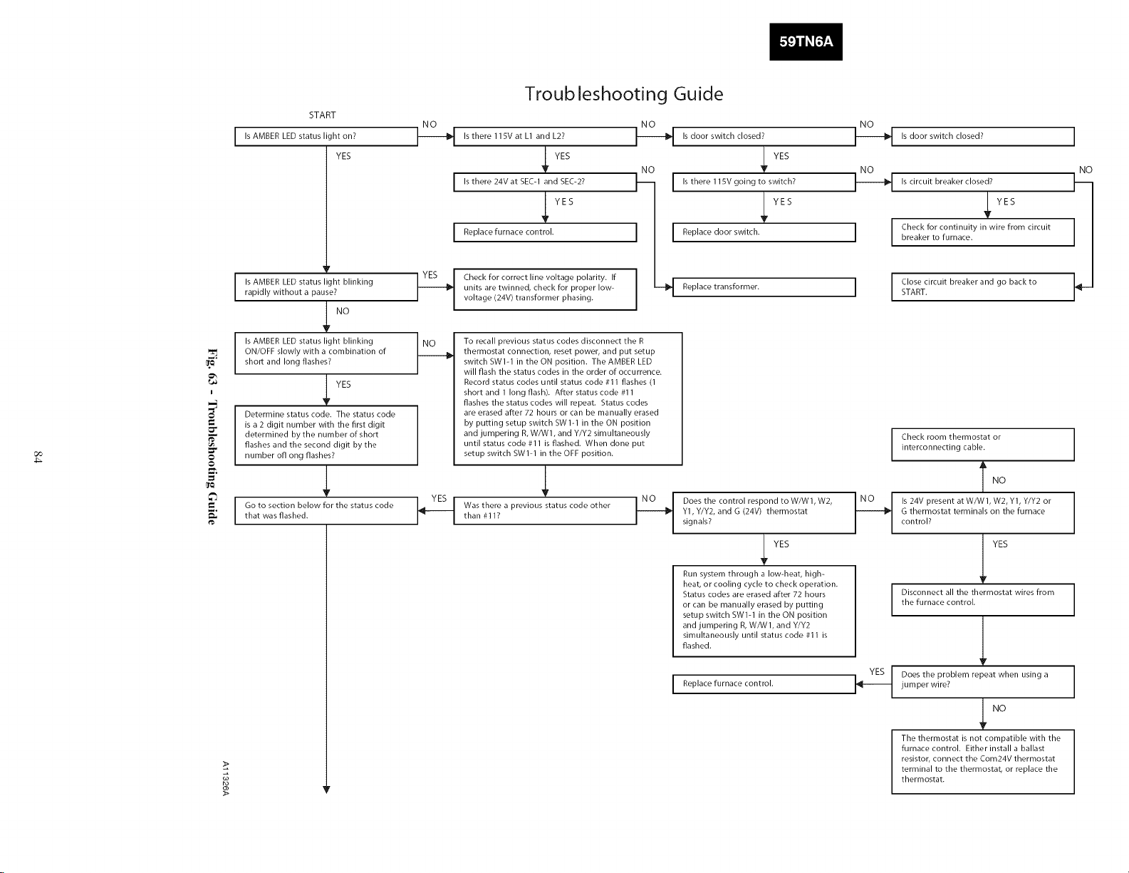
START
IsAMBERLEDstatus light on?
YES
Troub leshooting Guide
-_ s there115V at L1 andL2?
I Is there 24V at SEC-1 and SEC-2?
YES
Is door switch closed?
YES
I"_ I Is there 115V going to switch?
Is door switch closed?
Is circuit breaker closed?
]
NO
_! YES
Replacefurnace control.
I s AMBER LED status light blinkingrapidly without a pause?
1! NO
ON/OFF slowly with a combination of
I Is AMBER LED status light blinking
short and long flashes?
i
Determine status code. The status code
is a 2 digit number with the first digit
determined bythe number of short
co
flashes and the second digit by the
number off ong flashes?
_°
!! YES
I__ Check for correct line voltage polarity. If
,L
that was flashed.
Go to section below for the status code
t_
units are twinned, check for proper low-
voltage (24V) transformer phasing.
To recall previous status codes disconnect the R
thermostat connection, reset power, and put setup
switch BWI-I in the ON position. The AMBER LED
will flash the status codes in the order of occurrence.
Record status codes until status code #I I flashes (I
short and 1 long flash). After status code #11
flashes the status codes will repeat. Status codes
are erased after 72 hours or can be manually erased
by putting setup switch BW1-1 in the ON position
and jumpering R, W/W1, and Y/Y2 simultaneously
until status code #11 is flashed. When done put
setup switch BW1-1 in the OFF position.
,L
Was there a previous status code otherthan #I I?
l [ Replace d..... itch.
--_ Replace transformer.
t_ Does the control respond to WA_VI, W2,
Y1, Y/Y2, and G (24V) thermostat
signals?
Run system through a low-heat, high-
heat, or cooling cycle to check operation.
Status codes are erased after 72 hours
or can be manually erased by putting
setup switch SWl-1 in the ON position
and jumpering R, W/W1, and Y/Y2
simultaneously until status code #I I is
flashed.
I Replace furnace control.
YES
7! YES
1
I
Check for continuity in wire from circuit
breaker to furnace.
Close circuit breaker and go back to
START.
Check room thermostat or
interconnecting cable.
Is 24V present at WA,VI, W2, Y1, Y/Y2 or
G thermostat terminals on the furnace
control?
Disconnect all the thermostat wires from
the furnace control.
Does the problem repeat when using a
jumper wire?
YES
l.o
I YES
l
1.°
The thermostat is not compatible with the
furnace control. Either install a ballast
resistor, connect the Com24V thermostat
terminal to the thermostat, or replace the
thermostat.
Page 85
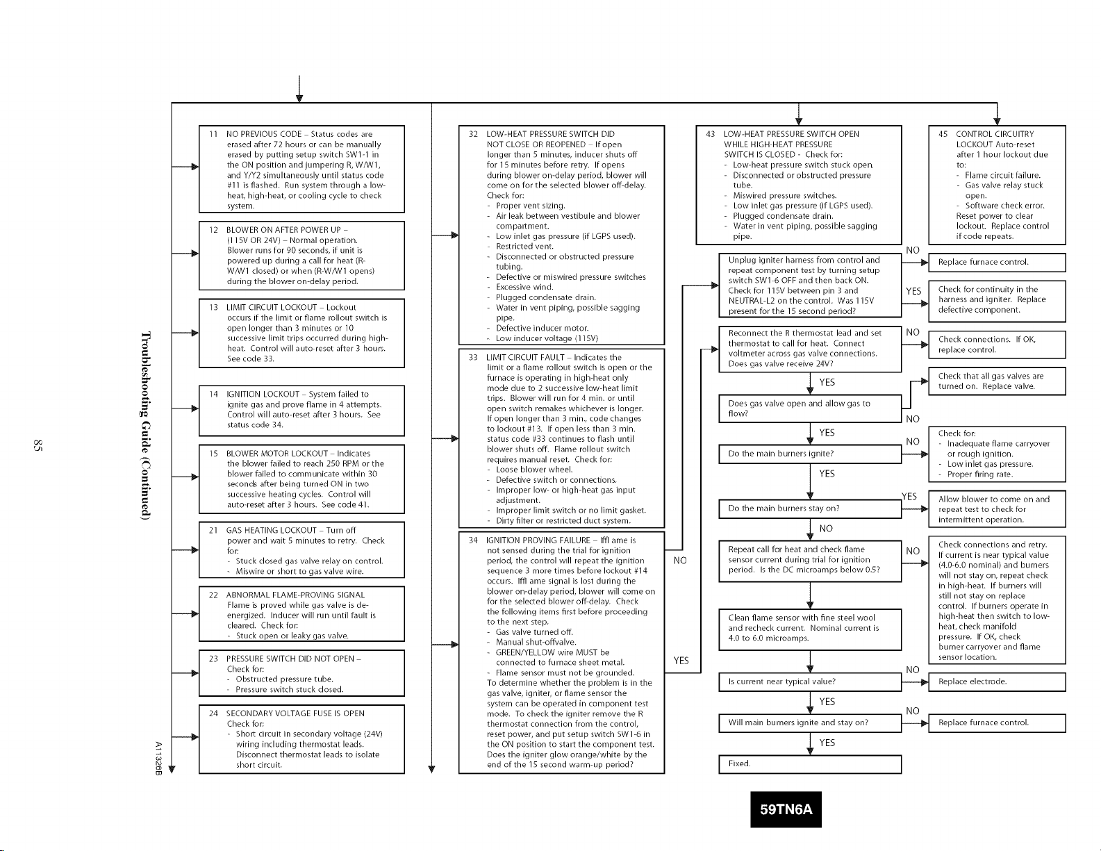
NO PREVIOUS CODE Status codes are
erased after 72 hours or can be manually
erased by putting setup switch SWl-] in
the ON position and jumpering R, W/W1,
and Y/Y2 simultaneously until status code
#1 ] is flashed. Run system through a low-
heat, high-heat, or cooling cycle to check
system,
12 BLOWER ON AFTER POWER UP
(115V OR 24V) Normal operation.
Blower runs for 90 seconds, if unit is
powered up during a call for heat (R-
W/W1 closed) or when (R-W/W1 opens)
during the blower on-delay period.
13 LIMIT CIRCUIT LOCKOUT Lockout
occurs if the limit or flame rollout switch is
open longer than 3 minutes or 10
successive limit trips occurred during high-
heat. Control will auto-reset after 3 hours.
See code 33.
14 IGNITION LOCKOUT System failed to
ignite gas and prove flame in 4 attempts.
Control will auto-reset after 3 hours. See
status code 34.
oo
EB
15 BLOWER MOTOR LOCKOUT Indicates
the blower failed to reach 250 RPM or the
blower failed to communicate within 30
seconds after being turned ON in two
successive heating cycles, Control will
auto-reset after 3 hours, See code 41.
21 GAS HEATING LOCKOUT Turn off
power and wait 5 minutes to retry. Check
for:
- Stuck closed gas valve relay on control.
- Miswire or short to gas valve wire.
22 ABNORMAL FLAME-PROVING SIGNAL
Flame is proved while gas valve is de-
energized. Inducer will run until fault is
cleared. Check for:
- Stuck open or leaky gas valve.
23 PRESSURESWITCH DID NOT OPEN
Check for:
- Obstructed pressure tube.
- Pressure switch stuck closed.
24 SECONDARY VOLTAGE FUSE IS OPEN
Check for:
- Short circuit in secondary voltage (24V)
wiring including thermostat leads,
Disconnect thermostat leads to isolate
short circuit,
32
LOW-HEAT PRESSURESWITCH DID
NOT CLOSE OR REOPENED If open
longer than 5 minutes, inducer shuts off
for 15 minutes before retry, If opens
during blower on-delay period, blower will
come on for the selected blower off-delay.
Check for:
- Proper vent sizing.
- Air leak between vestibule and blower
compartment.
- Low inlet gas pressure (if LGPS used).
- Restricted vent,
- Disconnected or obstructed pressure
tubing,
- Defective or miswired pressure switches
- Excessive wind.
- Plugged condensate drain.
- Water in vent piping, possible sagging
pipe,
- Defective inducer motor.
- Low inducer voltage (115V)
33
LIMIT CIRCUIT FAULT Indicates the
limit or a flame rollout switch is open or the
furnace is operating in high-heat only
mode due to 2 successive low-heat limit
trips. Blower will run for4 rain. or until
open switch remakes whichever is longer,
If open longer than 3 rain., code changes
to lockout #13. If open less than 3 rain.
status code #33 continues to flash until
blower shuts off. Flame rollout switch
requires manual reset, Check for:
- Loose blower wheel.
- Defective switch or connections,
- Improper low- or high-heat gas input
adjustment.
- Improper limit switch or no limit gasket,
- Dirtyfllter or restricted duct system.
34
IGNITION PROVING FAILURE Iffl ame is
not sensed during the trial for ignition
period, the control will repeat the ignition
sequence 3 more times before lockout #14
occurs. Iffl ame signal is lost during the
blower on-delay period, blower will come on
for the selected blower off-delay. Check
the following items first before proceeding
to the next step.
- Gas valve turned off.
- Manual shut-offvalve.
- GREEN/YELLOW wire MUST be
connected to furnace sheet metal.
- Flame sensor must not be grounded.
To determine whether the problem is in the
gas valve, igniter, or flame sensor the
system can be operated in component test
mode. To check the igniter remove the R
thermostat connection from the control,
reset power, and put setup switch SW1-6 in
the ON position to start the component test.
Does the igniter glow orange/white by the
end of the 15 second warm-up period?
43 LOW-HEAT PRESSURESWITCH OPEN
WHILE HIGH-HEAT PRESSURE
SWITCH IS CLOSED - Check for:
- Low-heat pressure switch stuck open.
- Disconnected or obstructed pressure
tube.
- Miswired pressure switches,
- Low inlet gas pressure (if LGPS used).
- Plugged condensate drain.
- Water in vent piping, possible sagging
pipe.
Unplug igniter harness from control and
repeat component test by turning setup
switch SW1-6 OFF and then back ON.
Check for 115V between pin 3 and
NEUTRAUL2 on the control. Was 115V
present for the 15 second period?
Reconnect the R thermostat lead and set
thermostat to call for heat. Connect
voltmeter across gas valve connections.
Does gas valve receive 24V?
flow?
I Does gas valve open and allow gas to
I Do the main b ....... ignite? I_
i
I Do the main b ........ tay on?
i /
m
N
YI
Repeat call for heat and check flame INO
sensor current during trial for ignition
period. Is the DC microamps below 0.57
Clean flame sensor with fine steel wool
and recheck current. Nominal current is
4.0 to 6.0 microamps.
I Is current near typical value?
I Will main burners ignite and stay on?
l Fixed.
YES
YES
YES
YES
YES
45 CONTROL CIRCUITRY
LOCKOUT Auto-reset
after 1 hour lockout due
to:
- Flame circuit failure.
- Gas valve relay stuck
open.
- Software check error.
Reset power to clear
lockout. Replace control
NO
]_l Check connections. If OK,
.YES
/
¢q
I_ Replace furnace control.
if code repeats.
Check for continuity in the
harness and igniter. Replace
Replace furnace control.
defective component.
replace control.
turned on. Replace valve.
Check that all gas valves are
Check for:
- Inadequate flame carryover
or rough ignition.
- Lowinlet gas pressure.
- Proper firing rate.
Allow blower to come on and
repeat test to check for
intermittent operation.
Check connections and retry,
If current is near typical value
(4.0-6.0 nominal) and burners
will not stay on, repeat check
in high-heat. If burners will
still not stay on replace
control. If burners operate in
high-heat then switch to low-
heat, check manifold
pressure. If OK, check
burner carryover and flame
sensor location.
Replace electrode,
Page 86
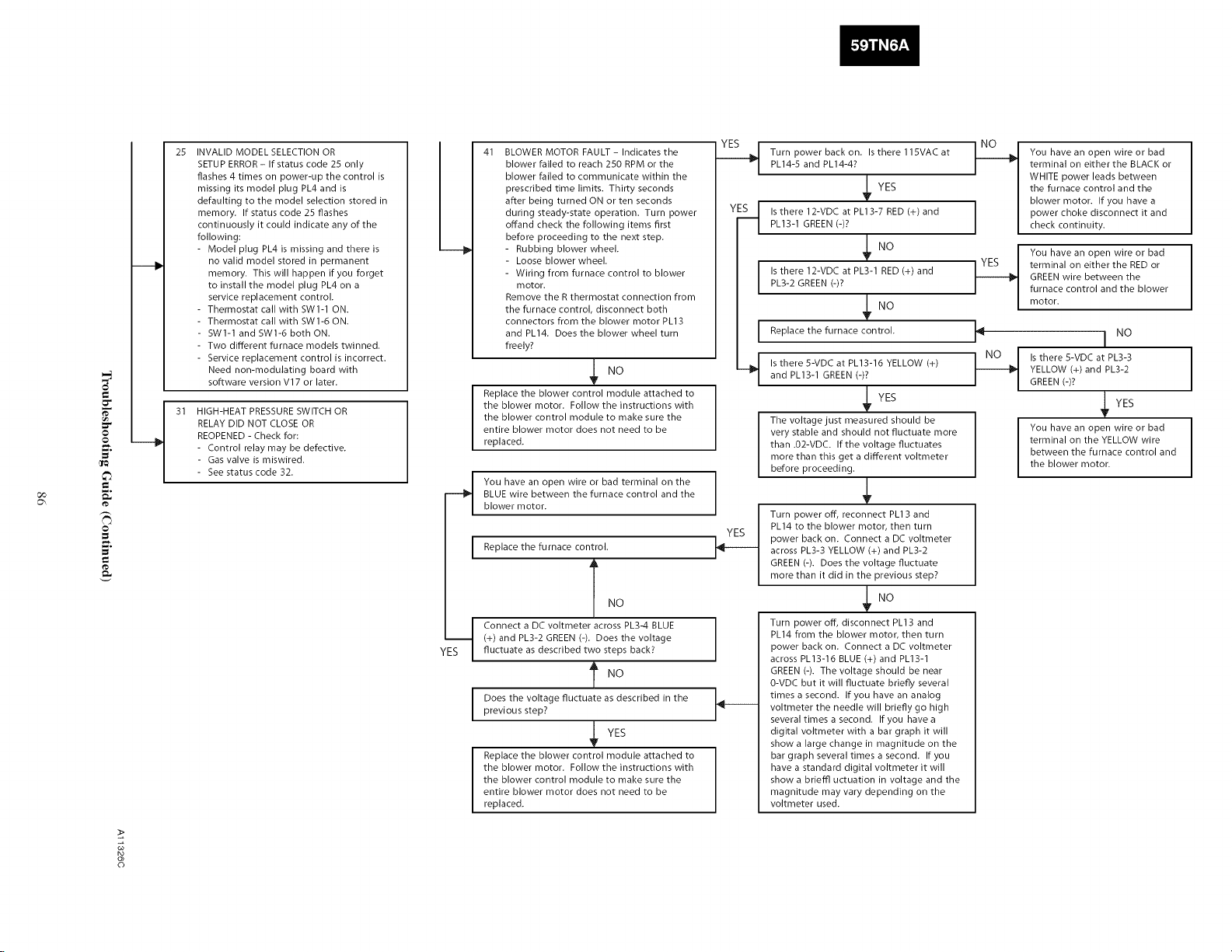
25 INVALID MODEL SELECTION OR
SETUP ERROR- If status code 25 only
flashes 4 times on power-up the control is
missing its model plug PL4 and is
defaulting to the model selection stored in
memory. If status code 25 flashes
continuously it could indicate any of the
following:
- Model plug PL4 is missing and there is
no valid model stored in permanent
memory. This will happen if you forget
to install the model plug PL4 on a
service replacement control.
- Thermostat call with SWl-1 ON.
- Thermostat call with SWl-6 ON.
- SWl-1 and SW]-6 both ON.
- Two different furnace models twinned.
- Service replacement control is incorrect.
Need non-modulating board with
software version Vl 7 or later.
HIGH-HEAT PRESSURE SWITCH OR
RELAY DID NOT CLOSE OR
_°
GO
t_
_°
t_
REOPENED - Check for:
- Control relay may be defective.
- Gas valve is miswired.
- See status code 32.
41 BLOWER MOTOR FAULT- Indicates the
blower failed to reach 250 RPM or the
blower failed to communicate within the
prescribed time limits. Thirty seconds
after being turned ON or ten seconds
during steady-state operation. Turn power
offand check the following items first
before proceeding to the next step.
- Rubbing blower wheel.
- Loose blower wheel.
- Wiring from furnace control to blower
motor.
Remove the R thermostat connection from
the furnace control, disconnect both
connectors from the blower motor PL13
and PL]4. Does the blower wheel turn
freely?
Replace the blower control module attached to
the blower motor. Follow the instructions with
the blower control module to make sure the
entire blower motor does not need to be
replaced.
You have an open wire or bad terminal on the
BLUE wire between the furnace control and the
blower motor.
Replace the furnace control.
._ Turn power back on. Is there115VAC atPL14-S and PL14-47
q s there 12-VDC at PL13-7 RED (+) andPL13-1 GREEN (-)7
PL3-2 GREEN (-)?
I Is there 12-VDC at Pk3-1 RED (+) and
Replace the furnace control.
Is there 5-VDC at PL13-16 YELLOW (+)
and PL13-1 GREEN (-)?
q
The voltage just measured should be
very stable and should not fluctuate more
than .02-VDC. If the voltage fluctuates
more than this get a different voltmeter
before proceeding.
Turn power off, reconnect PL13 and
PL]4 to the blower motor, then turn
power back on. Connect a DC voltmeter
across PL3-3 YELLOW (÷) and PL3-2
GREEN (-). Does the voltage fluctuate
more than it did in the previous step?
YES
No
YES
terminal on either the BLACK or
WHITE power leads between
the furnace control and the
blower motor. If you have a
You have an open wire or bad
power choke disconnect it and
check continuity.
You have an open wire or bad
terminal on either the RED or
GREEN wire between the
furnace control and the blower
motor.
I NO
Is there S-VDC at PL3-3 I
YELLOW (+) and PL3-2
GREEN (-)?
YES
You have an open wire or bad I
terminal on the YELLOW wire
between the furnace control and
I
the blower motor.
I
n
I
Connect a DC voltmeter across Pk3-4 BLUE
(+) and Pk3-2 GREEN (-). Does the voltage
fluctuate as described two steps back?
Does the voltage fluctuate as described in the
I
previous step?
_ YES
Replace the blower control module attached to
the blower motor. Follow the instructions with
the blower control module to make sure the
entire blower motor does not need to be
replaced.
©
Turn power off, disconnect Pkl3 and
PL14 from the blower motor, then turn
power back on. Connect a DC voltmeter
across Pk]3-16 BLUE (+) and Pk]3-]
GREEN (-). The voltage should be near
0-VDC but it will fluctuate briefly several
times a second. If you have an analog
voltmeter the needle will briefly go high
several times a second. If you have a
digital voltmeter with a bar graph it will
show a large change in magnitude on the
bar graph several times a second. If you
have a standard digital voltmeter it will
show a brieffl uctuation in voltage and the
magnitude may vary depending on the
voltmeter used.
Page 87
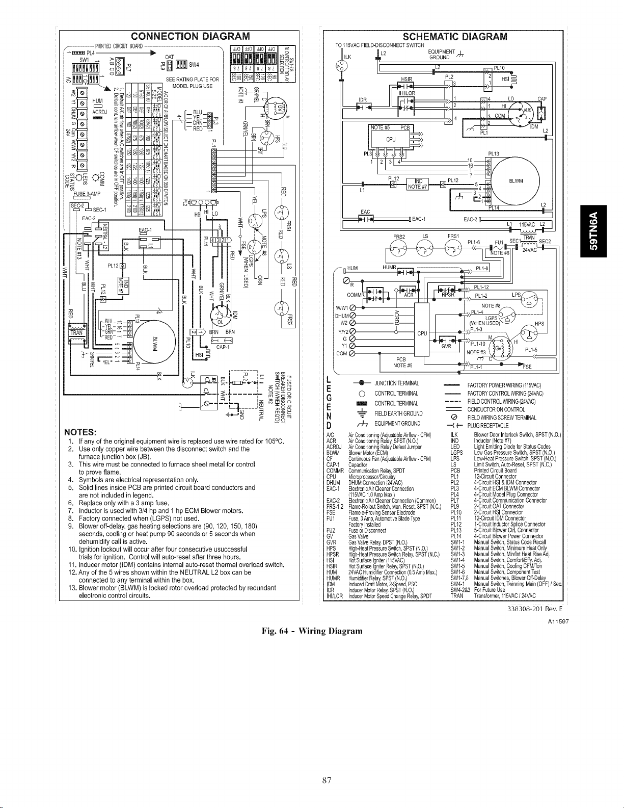
CONNECTION DIAGRAM
SEE RATING PLATE FOF
MODEL PLUG USE
HSI LO
I
BRN BRN
TO115VACFIELD-DISCONNECTSWITCH
K _L2 EQUIPMENT
PL31_ _ _ _1 PL13
_ PLY2 _ _PL12 r _ nlwM 1
GROUND _"
< --4qA ....... )
I rr-e \ j
SCHEMATIC DIAGRAM
EAC [ _
HUM
__EAO-_ EAC-__
FRS2 LS FRS1
PL1-6
o H_LHL_ CAP-
i i
NOTES:
1. If any of the original equipment wire is replaced use wire rated for 105°C.
2. Use only copper wire between the disconnect switch and the
furnace junction box (JB).
3. This wire must be connected to furnace sheet metal for control
to prove lame.
4. Symbols are electrical representation only.
5. Solid lines inside PCB are printed circuit board conductors and
are Rot included in legend.
6. Replace only with a 3 amp fuse.
7. Inductor is used with 3/4 hp and 1 hp ECM Blower motors.
8. Factory connected when (LGPS) not used.
9. Blower off-delay, gas heating selections are (90, 120, 150, 180)
seconds, cooling or heat pump 90 seconds or 5 seconds when
dehumidify call is active.
10. Ignition lockout will occur after four consecutive usuccessful
trials for ignition. Control will auto-reset after three hours.
11. Inducer motor (IDM) contains internal auto-reset thermal overload switch.
12. Any of the 5 wires shown within the NEUTRAL L2 boxcan be
connected to any terminal within the box.
13. Blower motor (BLWM) is locked rotor overload protected by redundant
electronic control circuits.
Fig. 64 - Wiring Diagram
--me
Qm_
JUNCTIONTERMINAL
0 CONTROLTERMINAL FACTORYCONTROLWIRING(24VAC)
o_
I I1_ CONTROLTERMINAL
"J'- FIELDEARTHGROUND -- CONDUCTORONCONTROL
I _-- _ FIELDWIRINGSCREWTERMINAL
/-)7 EQUIPMENTGROUND --4 e,-, PLUGRECEPTACLE
NC AirConditioning(AdjustableAirflow-CFM) ILK BlowerDoorInterlockSwitch,SPST(N,O,)
ACR Air ConditioningRelay,SPST(N.O.) IND Inductor(Note#7)
ACRDJ AirConditioningRelayDefeatJumper LED LightEmittingDiodeforStatusCodes
BLWM BlowerMotor(ECM) LOPS LowGasPressureSwitch,SPST(N,O,)
CF ContinuousFan AdjustableAirflow-CFM LPS Low-HeatPressureSwitch,SPST N.O.
CAP-f Capacitor LS Lm t Sw tch,Auto-Reset,SPSTN,C,
COMMR CommunicationRelay,SPDT PCB PrintedCircuitBoard
CPU Microproceasor/Cirouitty PL1 12-CircuitConnector
DHUM DHUMConnection24VAC) PL2 4-CircuitHSI& IDMConnector
EAC-1 EectronoA rC eanerConnecton PL3 4-ClmuitECMBLWMConnector
(115VAC1,0AmpMax,) PL4 4-CircuitModelPlugConnector
EAC-2 ElectronicAirCleanerConnectionCommon) PL7 4-CimuitCommunicationConnector
FRS-I,2 Fame-RooutSwitch,Man,Reset,SPST N,C, PL9 2-CircuitOATConnector
FSE Flamee-ProvingSensorElectrode PLfO 2-CgcuitHSlConnector
FU1 Fuse,3Amp,AutomotiveBladeType PLff 12-CirculIDMConnector
FactoryInstalled PL12 1-CircuitInductorSpliceConnector
FU2 FuseorDisconnect PLf3 5-CircuitBlowerGirl,Connector
GV GasValve PU4 4-CircuitBlowerPowerConnector
GVR GasValveRelay,DPST(N,O,) SWI-1 ManualSwitch,StatusCodeRecall
HPS High-HeatPressureSwitch,SPST(N.O.) SWl-2 ManualSwitch,MinimumHeatOnly
HPSR High-HeatPressureSwitchRelay,SPSTN,C, SWl-3 ManualSwitch,MWIntHeatRiseAdj.
HSI HotSurfaceIgniter(115VAC) SW1-4 ManualSwitch,Comfort/Effy,Ad,
HSlR HotSurfaceIgniterRelay,SPST(N.O.) SW1-5 ManualSwitch,CoolingCFM/Ton
HUM 24VACHumidifierConnection(0,5AmpMax,) SWf-6 ManualSwitch,ComponentTest
HUMR HumidifierRelay,SPSTN,O, SWl-7,8 ManualSwitches,BlowerOff-Delay
IDM InducedDraftMotor,2-Speed,PSC SW4-1 ManualSwitch,TwinningMain(OFF)/ Sec,
IDR InducerMotorRelay,SPST(N,O,) SW4-2&3 ForFutureUse
IHI/LOR InducerMotorSpeedChangeRelay,SPDT TRAN Transformer,115VAC/ 24VAC
_ FACTORYPOWERWIRING(115VAC)
FIELDCONTROLWIRING(24VAC)
338308:20] Rev. E
Al1597
87
Page 88
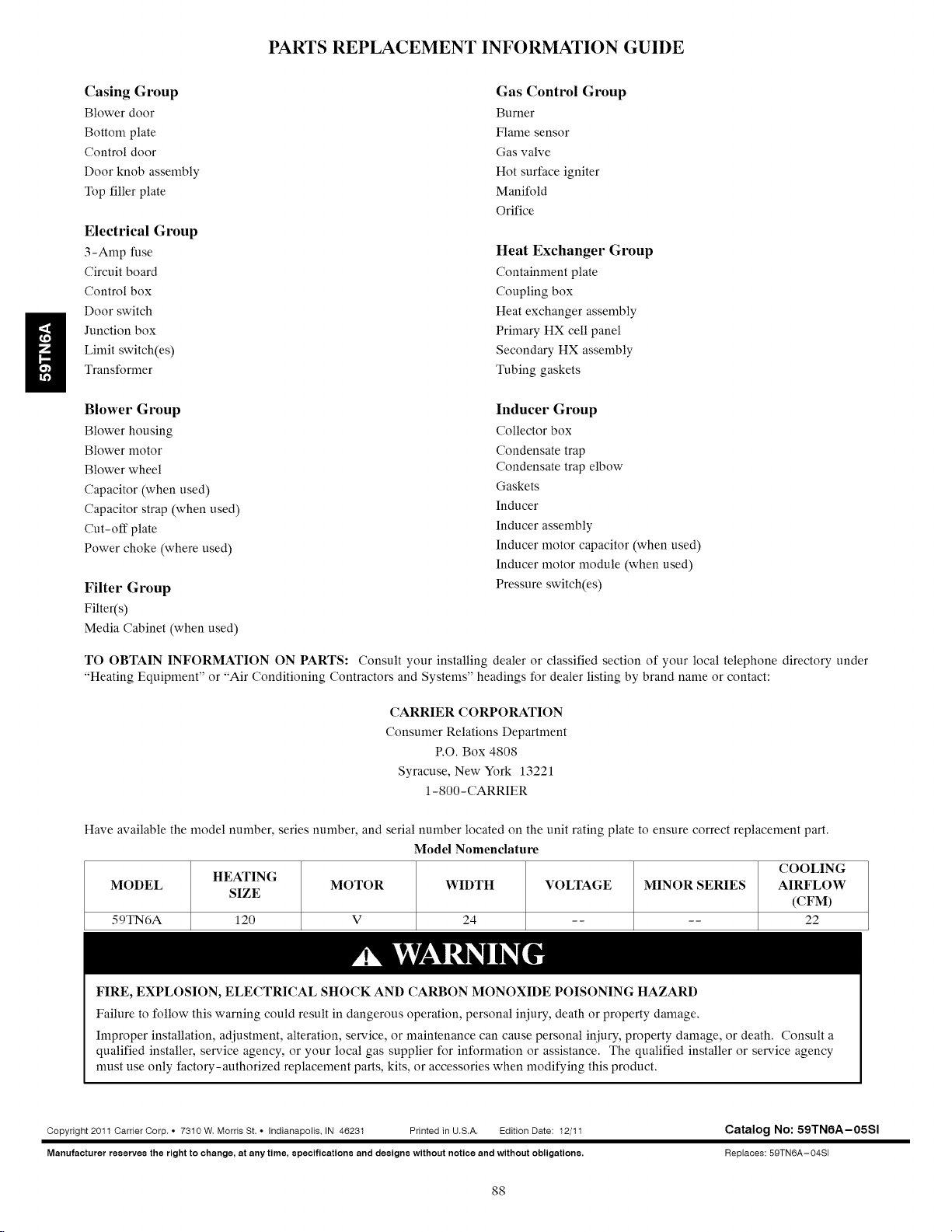
PARTS REPLACEMENT INFORMATION GUIDE
ii
Casing Group
Blower door
Bottom plate
Control door
Door knob assembly
Top filler plate
Electrical Group
3-Amp fuse
Circuit board
Control box
Door switch
Junction box
Linfit switch(es)
Transformer
Blower Group
Blower housing
Blower motor
Blower wheel
Capacitor (when used)
Capacitor strap (when used)
Cut-off plate
Power choke (where used)
Filter Group
Filter(s)
Media Cabinet (when used)
Gas Control Group
Burner
Flame sensor
Gas valve
Hot surface igniter
Manifold
Orifice
Heat Exchanger Group
Containment plate
Coupling box
Heat exchanger assembly
Primary HX cell panel
Secondary HX assembly
Tubing gaskets
Inducer Group
Collector box
Condensate trap
Condensate trap elbow
Gaskets
Inducer
Inducer assembly
Inducer motor capacitor (when used)
Inducer motor module (when used)
Pressure switch(es)
TO OBTAIN INFORMATION ON PARTS: Consult your installing dealer or classified section of your local telephone directory under
"Heating Equipment" or "Air Conditioning Contractors and Systems" headings for dealer listing by brand name or contact:
CARRIER CORPORATION
Consumer Relations Department
P.O. Box 4808
Syracuse, New York 13221
1 - 800 - CARRIER
Have available the model number, series number, and serial number located on the unit rating plate to ensure correct replacement part.
Model Nomenclature
MODEL MOTOR WIDTH VOLTAGE MINOR SERIES AIRFLOW
59TN6A 120 V 24 .... 22
HEATING COOLING
SIZE (CFM)
!
FIRE, EXPLOSION, ELECTRICAL SHOCK AND CARBON MONOXIDE POISONING HAZARD
Failure to follow this warning could result in dangerous operation, personal injury, death or property damage.
Improper installation, adjustment, alteration, service, or maintenance can cause personal injury, property damage, or death. Consult a
qualified installer, service agency, or your local gas supplier for information or assistance. The qualified installer or service agency
must use only factory-authorized replacement parts, kits, or accessories when modifying this product.
Copyright 2011 Carrier Corp. * 7310 W. Morris St. * Indianapolis, IN 46231 Printed in U.S.A. Edition Date: 12/11
Manufacturer reserves the right to change, at any time, specification8 and design8 without notice and without obligations,
88
Catalog No: 59TN6A-05SI
Replaces: 59TN6A- O4Sl
 Loading...