

Carrier 58MVP100, 58MVP060 Installation Guide
58NVP
[HEATING & COOUNG
\isit_ v_wcarrier.corn
VariabMe-Capacity Condensing Gas Furnace
tnstammation, Start-Up, and Operating
For Sizes 040 120, Series t70
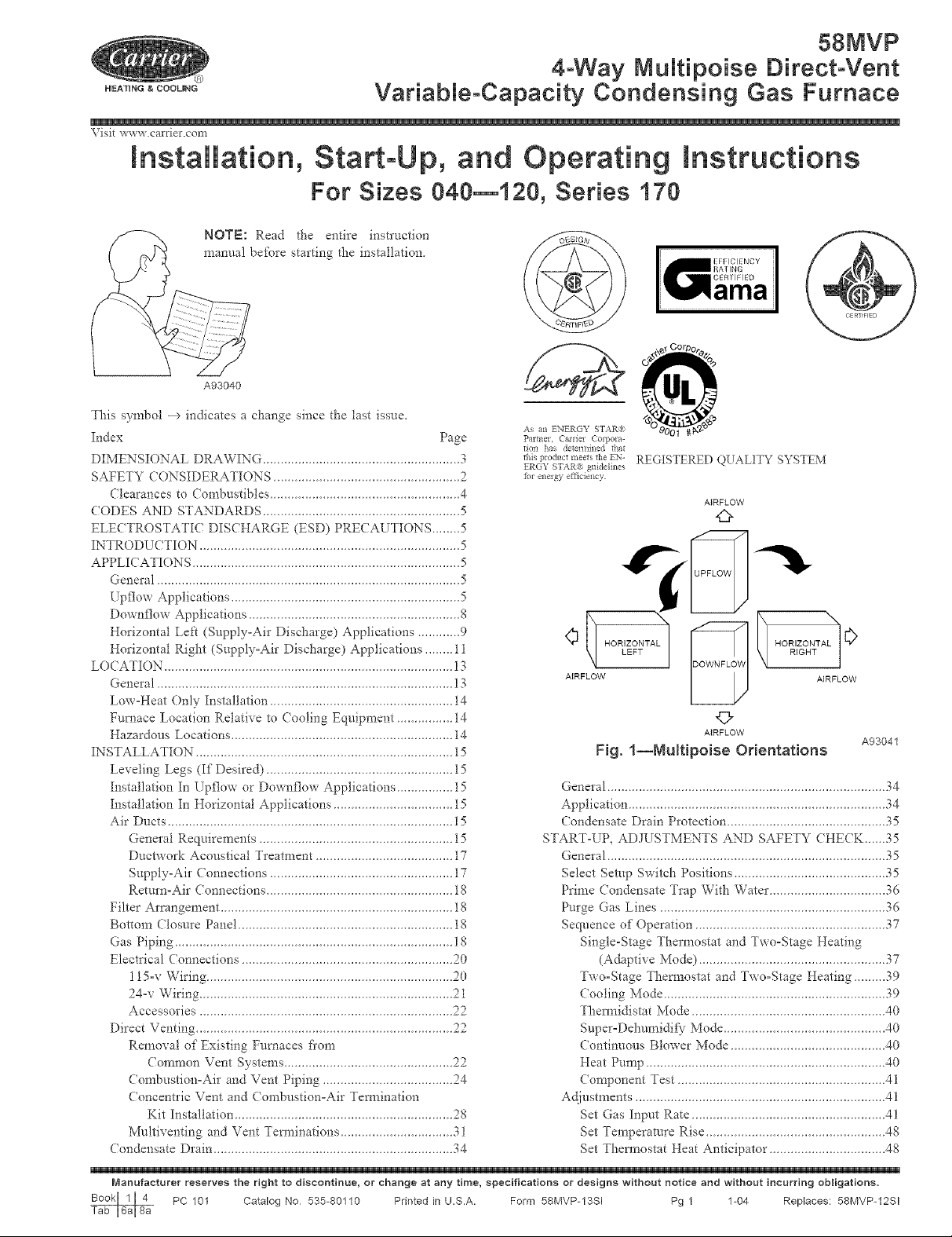
NOTE: Read the entire instruction
manual bei\_re starting the installation
A93040
4-VVay MuMtipoise Dkect-Vent
This symbol --> indicates a change since the last issue,
Index Page
DIMENSIONAL DRAWING ........................................................ 3
SAFETY CONSIDERATIONS ..................................................... 2
Clearances to Combustibles ...................................................... 4
<ODES AND STANDARDS ........................................................ 5
ELE< TROSTATIC DIS<HARGE (ESD) PRE(AUTIONS ........ 5
INTRODU< TION .......................................................................... 5
APPLICATIONS ............................................................................ 5
General ...................................................................................... 5
Upf]ow Applications ................................................................. 5
Downflow Applications ............................................................ 8
Horizontal Left (Supply-Air Discharge) Applications ............ 9
Horizontal Right (Supply-Air Discharge) Applications ........ 11
LO< ATION .................................................................................. 13
General .................................................................................... ]3
Low-Heat Only Installation .................................................... 14
Furnace Location Relative to ( ooling Equipment ................ 14
Hazardous Locations ............................................................... i4
INSTALLATION ......................................................................... 15
Leveling Legs (If Desired) ..................................................... 15
Installation In [pflow or Downflow Applications ................ 15
Installation In Horizontal Applications .................................. 15
Air Ducts ................................................................................. ] 5
General Requirements ....................................................... 15
Ductwork Acoustical Treatment ....................................... 17
Supply-Air Connections .................................................... 17
Return=Air < onnections ..................................................... 18
Filter Arrangement .................................................................. 18
Bottom Closure Panel ............................................................. i8
Gas Piping ............................................................................... l 8
Electrical ( onnections ............................................................ 20
] 15-v Wiring ...................................................................... 20
24-v Wiring ........................................................................ 21
Accessories ........................................................................ 22
Direct Venting ......................................................................... 22
Removal of Existing Furnaces fl'om
( ommon Vent Systems ......................... 22
Combustion-Air and Vent Piping .................... 24
Concentric Vent and Combustion-Air Temaination
Kit Installation ................................ 28
Multiventing and Vent Tem_inations ................. 3 l
Condensate Drain ................................. 34
As an ENERGY STAR're
Pmmer, Carrier CoLvora-
don has detem*ined that
this product meets the EN'-
FR(SY S fAR_ guidelines
fbr energy effldency
START-UP, ADJUSTMENTS AND SAFETY CHECK. _ 35
REGISTERED QUALITY SYSTEM
AIRFLOW
O
¢
HORIZONTAL HORIZONTAL
LEFT RIGHT
AIRFLOW AIRFLOW
©
AIRFLOW
Fig. 1--NuRipoise Orientations
General ............................................................................... 34
Application ........................................ 34
Condensate Drain Protection ...................... 35
General ......................................... 35
Select Setup Switch Positions ........................................... 35
Prime < ondensate Trap With Water ................................. 36
Purge Gas Lines ................................................................ 36
Sequence of Operation ...................................................... 37
Single-Stage Thermostat and Two-Stage Heating
(Adaptive Mode) .......................... 37
Two-Stage Them_ostat and Two-Stage Heating ...... 39
Cooling Mode .............................. 39
Them_idistat Mode .......................... 40
Supe*-Dehumidif) Mode ............................ 40
Continuous Blower Mode ...................... 40
Heat Pump ................................ 40
Component Test ............................ 41
Ac{iustments ................................... 4 l
Set Gas Input Rate .......................... 41
Set Temperam*e Rise .......................... 48
Set Them_ostat Heat Anticipator .................. 48
A93041
Manufacturer reserves the right to discontinue, or change at any time, specifications or designs without notice and without incurring obligations.
PC 101 Catalog No 535-80110 Printed in U.S.A. Form 58MVP-13SI Pg 1 1-04 Replaces: 58MVP-12SI
(heck Safety Controls 49
Check Primary Limit Control 49
Check Pressure Switch ................................................. 49
(HE(KLIS7 ...................................................................... 49
SAFETY CONSIDERATtONS
Application of this furnace should be indoors with special
attention given to vent sizing and material, gas input rate, air
temperature rise, unit leveling, and unit sizing. Improper
installation or misapplication of furnace can require excessive
servicing or cause premature component _hilure.
Improper installatiom adjustment, aheration, sela'ice, mainte-
nanc< or use can cause carbon monoxide poisoning, explo-
sion, tire, electrical shock, or other conditions which may
cause personal Jr!iraY or property damage. Consult a qualified
installer, sela-ice agency, local gas supplier, or your distribu-
tor or branch _br information or assistance. The qualified
installer or agency must use only _i_ctory-authorized and
listed kits or accessories when modit)'ing this product. Failure
to follow this warning could result in electrical shock, firQ
personal injury; or death.
Installing and servicing heating equipment can be hazardous due to
gas and electrical components. Only trained and qualified
personnel should install, repair, or service heating equipment°
Untrained personnel can perform basic maintenance fhnctions
such as cleaning and replacing air Jilters. All other operations nmst
be performed by trained service personnel. When working on
heating equipment, observe precautions in literature, on tags, and
on labels attached to or shipped with unit and other safety
precautions that may apply.
These instructions cover the minimum requirements and conform
to existing national standards and safety codes. In some instances,
these instructions exceed certain local codes and ordinances,
especially those that may not have kept up with changing residen-
tial construction practices. We require these instructions as a
minimum ibr a saf_ installation.
Wear safety" glasses and work gloves. Have a fire extinguisher
available during start-up and adjustment procedures and service
calls.
Recognize safety informatiom This is the safety=alert symbol _.
When you see this symbol on the unit and in instructions or
manuals, be alert to the potential for personal injury.
Understand these signal words: DANGER, WARNING, CAU=
TION, and NOTE. These words are used with the safety-alert
symbol. DANGER identifies the most serious hazards which will
result in severe personal injury or death. WARNING signifies
hazards which could resuh in personal Jr!jury or death. CAUTION
is used to identi_}' unsafe practices which would result in minor
personal injury or product and property damage. NOTE is used to
highlight suggestions which will result in enhanced installation,
reliability, or operation.
Sheet metal parts may have sharp edges or bun's. Use care and
wear appropriate protective clothing and gloves when hart=
dling parts. Failure to _bllow this caution could result in
personal injury.
propane gases (see t\trnace rating plate) and for installation in
alcoves, attics, basements, closets, utility rooms, crawlspaces, and
garages. The furnace is factory-shipped :_br use with natural gas A
C.S.A. (formerly AGA and CGA) listed gas conversion kit is
required to convert fhmace fbr use with propane gas
See Fig. 3 for required clearances to combustibles
Maintain a l-in clearance fi'om combustible materials to supply air
ductwork for a distance of 36 inches horizontally from the fl/rnace.
See NFPA 90B or local code ibr t:t_rther requirements.
These furnaces SHALL NOT be installed directly or* carpeting,
tile, or any other combustible material other than wood flooring. In
downflow installations, factory accessow floor base MUST be
used when installed on combustible materials and wood flooring.
Special base is not required when this Nmace is installed on
manufacturer's (?oil Assembly Part No. CD5 or CK5, or when (Toil
Box Part No. KCAKC is used. These fl/rnaces are suitable for
.............. a structure built on site or a manufi_ctured building
completed at final site. The design of this Nmace line is NOT
C.S.A. (formerly AGA and CGA) design=certified for installation
in recreation vehicles or outdoors.
This t_umace is designed for continuous return-air minimum
temperature of 60 °F dh or intermittent operation down to 55°F db
such as when used with a night setback thermostat. Return-air
temperature must not exceed 85°F dh. Failure to lbllow these
return air limits may affect reliability of heat exchangers, motors
and controls. (See Fig. 4.)
These furnaces are shipped with the drain and pressure robes
connected for UPFLOW applications. Minor modifications are
required when used in DOW_NFLOW, HORIZONTAL RIGHT, or
HORIZONTAL LEFT (supply=air discharge direction) applica-
tions as shown in Fig. 1. See details in Applications section.
This furnace must be installed with a direct=vent (combustion air
and flue) system and a fi_ctory accessory temlination kit. In a
direct-vent system, all air for combustion is taken directly fiom the
outside atmosphere and all flue products are discharged to the
outside atmosphere. See fl/mace and factoo" accesso_' termination
kit instructions for proper installation.
Never test for gas leaks with an open flame. Use a commercially
available soap solution made specifically for the detection of leaks
to check all connections as specified in the GAS PIPING section
of these instructions.
Always install furnace to operate within the furnace's intended
temperature=rise range with a duct system which has an external
static pressure within the allowable range as specified in the SET
TEMPERATURE RISE section of these instructions.
When a furnace is installed so that the supply ducts car_- air
circulated by the fimaace to areas outside the space containing the
furnace, the remm air must also be handled by a duct(s) sealed to
the furnace casing and tem_inating outside the space containing the
ftmaace
A gas=fired furnace _br installation in a residential garage must be
installed as specified in the Hazardous Locations section and Fig.
5.
The furnace is not to be used for temporaw heating of buildings or
structures under construction unless the furnace installation and
operation complies with first CAUTION in the LOCATION
section of these instructions.
The 58MVP Muhipoise Condensing Gas=Fired Furnaces are
CSA, (formerly AGA and CGA) design-certified _br natural and
O
AIRFLOW
TYP
OUTLET
A m
, 1biN DiA GAS CONN
27
CONDENSATE DRAIN
TRAP LOCATION _
(DOWNFLOW &
HORIZONTAL RIGHT)
OR ALTERNATE
30 i_,,
7m-IN DIA
POWER CONN
I_z-IN DIA
THERMOSTAT ENTRY
)NN
1
18 _,_
i
I SiDE INLET
I
I
I
CONDENSATE
SiDE iNLET
DRAIN LOCATION
(UPFLO\A/}
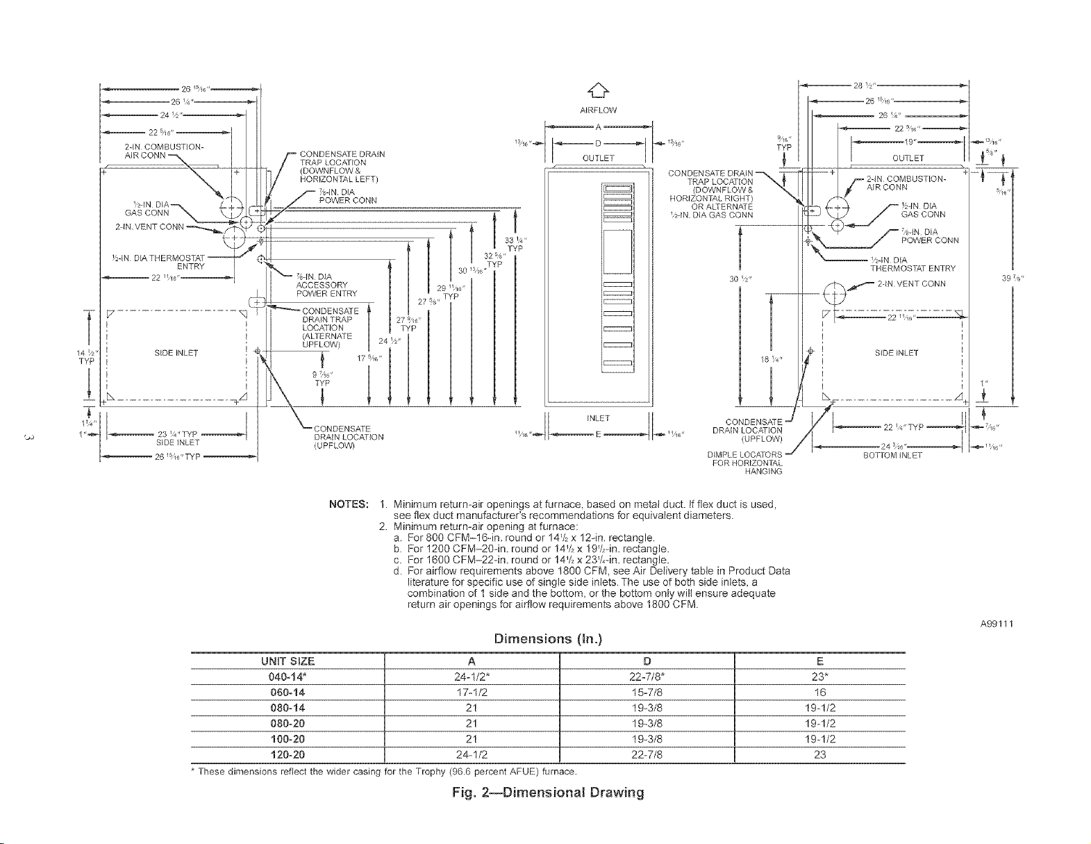
NOTES:
1. Minimum return-air openings at furnace, based on metal duct. If flex duct is used,
see flex duct manufacturer's recommendations for equivalent diameters.
2. Minimum return-air opening at furnace:
a, For 800 CFM-16qn, round or 14V_x 12in, rectangle.
b. For 1200 CFM-20qn. round or 14V, x 19V2qn.rectangle.
c. For 1600 CFM-22-in. round or !4_/_x 23V,-in. rectangle.
d. For airflow requirements above 1800 CFM, see Air Delivery table in Product Data
literature for specific use of single side inlets. The use of both side inlets, a
combination of 1 side and the bottom, or the bottom only will ensure adequate
return air openings for airflow requirements above 1800 CFM.
UNIT SBZE A D E
040-14* 24-1/2" 22-7/8" 23*
060-14 17-1/2 15-7/8 16
080-14 21 19_3/8 19-1/2
080-20 21 19_3/8 19-1/2
100=20 21 19_3/8 19-1/2
120=20 24-1/2 22-7/8 23
* These dimensions reflect the wider casing for the Trophy (96,6 percent AFUE) furnace
Fig. 2--Dimensional Drawing
INLE_ DRA{N LOCATION
Dimensions (in.)
DIMPLE LOCATORS
FOR HORIZON 17_,L
HANGING
A99111
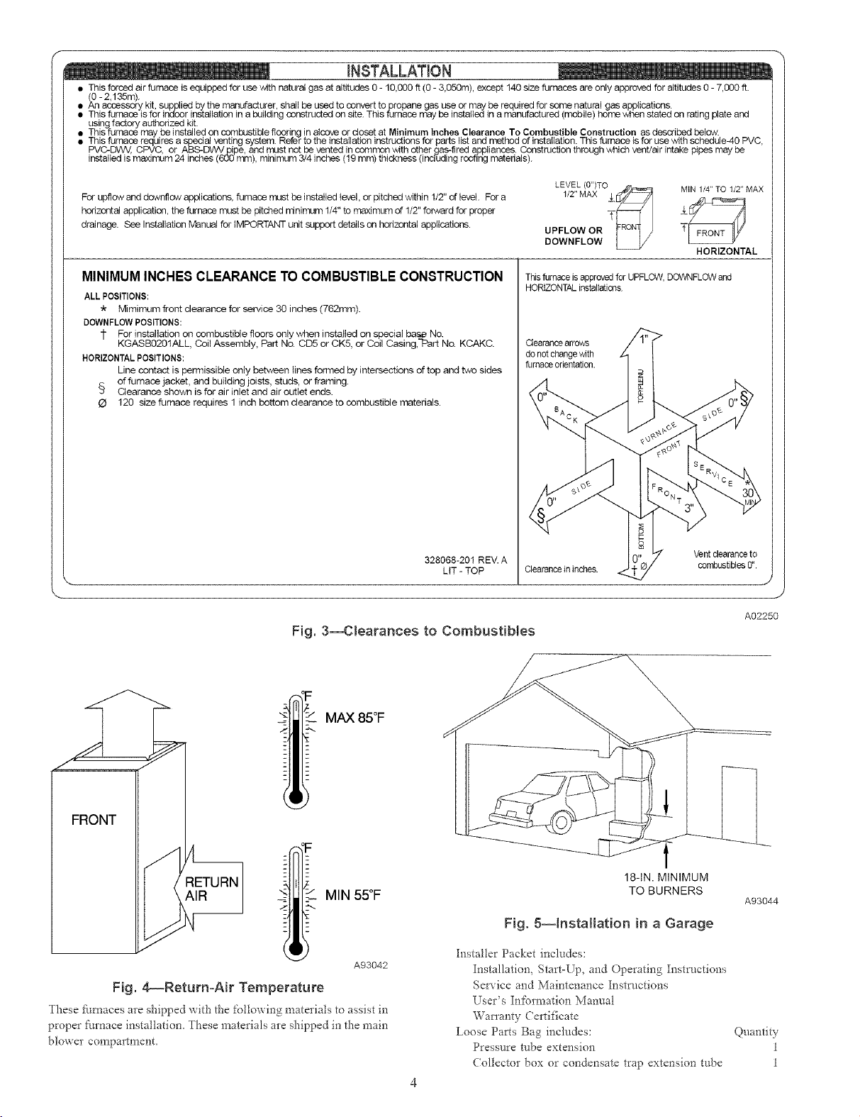
• This forced air furnace is equipped for use with natural gas at altitudes 0 - 10,000 ft (0 - 3,050m), except 140size furnaces are only approved for altitudes 0 - 7,000 ft.
(C0- 2,135m).
• An accessory kit, supplied by the manufacturer, shall be used to convert topropane gas use or may be required for some natural gas applications.
• This furnace is for indoor installation in a building constructed on site. This furnace nay be installed in a manufactured (mobile) home wden stated on rating plate and
using factory authorized kit.
This furnace may de installed on combustible flooring in alcove or closet at Minimum Inches Clearance To Combustible Construction as described below.
This furnace requires a special venting system. Refer to the installation instructions for parts list and method of installation. This furnace is for use with schedule-40 PVC,
PVC-DWV, CPVC, or ABS-DWV pipe, and must not be vented in seron-on with other Igas-fired appliances. Construction through which vent/air intake pipes may be
installed is maximum 24 inches (600 ram), minimum 3/4 inches (19 mm) thickness (including roofing n',atedals).
For upflow and downflow applications, furnace must be installed level, or pitched within 1/2" of level. For a
horizontal application, the furnace must be pitched ninimum 1/4" to maximum of 1/2" fo_verd for proper
drainage. See Installation Manual for IMPORTANT unit support details on horizontal applications.
MINIMUM INCHES CLEARANCE TO COMBUSTIBLE CONSTRUCTION
ALL POSITIONS:
* Mimimum front clearance for service 30 inches (762mm).
DOWNFLOWPOSITIONS:
1" For installation on combustible floors only when installed on special bas,_ No.
KGASB0201ALL, Coil Assembly, Part No. CD5 or CK5, or Coil Casing, Part No. KCAKC.
HORIZONTALPOSITIONS:
Line contact is permissible only between lines fon-ned by intersections of top and two sides
of furnace jacket, and building joists, studs, or framing.
,_ Clearance shown is for air inlet and air outlet ends.
O 120 size furnace requires 1 inch bottom clearance to combustible materials.
328068-201 REV. A
LtT - TOP
Fig. 3--Clearances to CombustiNes
LEVEL (0")TO ,,#_1_,._=_
1/2"MAX __
UPFLOW OR r_-,i/J
DOWNFLOW L_..Y
Thisfurnace isapl_oved forUPFLOW,DOWNFLOWand
HORIZONTALinstallations
Clearancearrows
do not change,with
fumace orientation.
MIN 1/4" TO t/2" MAX
HORIZONTAL
J
A02250
MAX 85°F
MIN 55°F
A93042
Fig. 4_Return-Air Temperature
These timaaces are shipped with the following materials to assist in
proper furnace installation, These materials are shipped in the main
blower compa_lment,
18-IN. MINIMUM
TO BURNERS
Fig. 5--installation in a Garage
Installer Packet includes:
Installation, Start=Up, and Operating Insm/ctions
Service and Maintenance Instructions
User's Inforn_ation Manual
Wan'anty Certificate
Loose Parts Bag includes:
Pressure tube extension
Collector box or condensate trap extension tube
A93044
Quantity
1
1
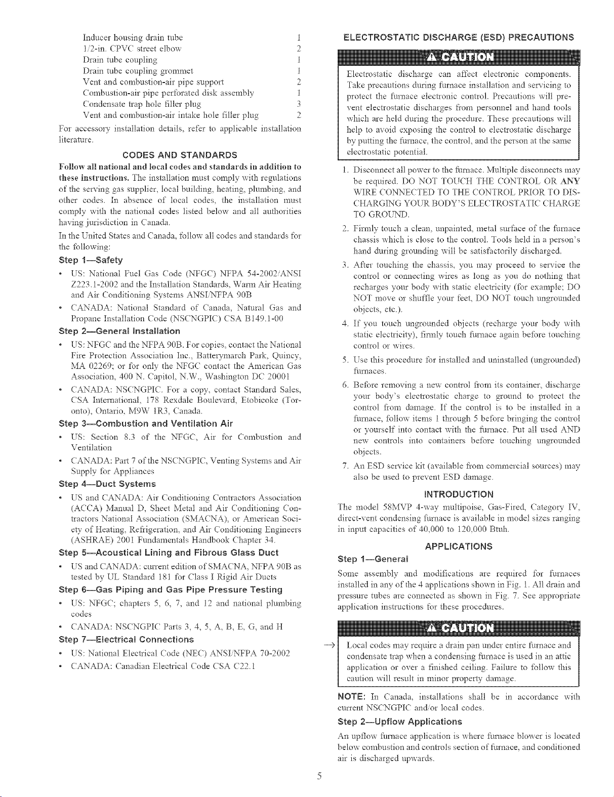
Inducer housing drain robe 1
1/2°in CPVC street elbow 2
Drain tube coupling 1
Drain tube coupling grommet 1
Vent and combustion°air pipe support 2
Combustion-air pipe perforated disk assembly 1
Condensate trap hole Illler plug 3
Vent and combustion°air intake hole filler plug 2
For accessory installation details, refBr to applicable installation
literature
CODES AND STANDARDS
Follow all national and local codes and standards in addition {o
these instructions° The installation must comply with regulations
of the serving gas supplier, local building, heating, plumbing, and
other codes. In absence of local codes, the installation must
comply with the national codes listed below and all authorities
having jurisdiction in Canada.
In the United States and Canada, follow all codes and standards for
the fbllowing:
Step l--Safety
* US: National Fuel Gas Code (NFGC) NFPA 54-2002/ANSI
Z223.1o2002 and the Installation Standards, Warm Air Heating
and Air Conditioning Systems ANSI NFPA 90B
* CANADA: National Standard of Canada, Natural Gas and
Propane Installation Code (NSCNGPIC) CSA BI49.!-00
Step 2--General hstaHation
* US: NFGC and the NFPA 90B. For copies, contact the National
Fire Protection Association Inc., Battewmarch Park, Quincy,
MA 02269; or for only the NFGC contact the American Gas
Association, 400 N. Capitol, N.W., Washington DC 20001
* CANADA: NSCNGPIC. For a copy, contact Standard Sales,
CSA International, 178 Rexdale Boulevard, Etobicoke (Tor-
onto), Ontario, M9W 1R3, Canada.
Step a--Combustion and Ventilation Air
* US: Section 8.3 of the NFGC, Air for (ombustion and
Ventilation
* CANADA: Part 7 of the NSCNGPIC, Venting Systems and Air
Supply fbr Appliances
Step 4--Duct Systems
* US and CANADA: Ab" (onditioning (ontractors Association
(ACCA) Manual D, Sheet Metal and Air Conditioning Con=
tractors National Association (SMACNA), or American Soci=
ety of Heating, Refrigeration, and Air Conditioning Engineers
(ASHRAE) 2001 Fundamentals Handbook Chapter 34.
Step 5--Acoustical Lining and Fibrous Glass Duct
* US and CANADA: current edition ofSMACNA, NFPA 90B as
tested by UL Standard 181 for Class I Rigid Air Ducts
Step 6--Gas Piping and Gas Pipe Pressure Testing
* US: NFG(; chapters 5, 6, 7, and 12 and national plumbing
codes
* CANADA: NSCNGPIC Parts 3, 4, 5, A, B, E, G, and H
Step 7--Electrical Connections
* US: National Electrical Code (NEC) ANSIiNFPA 70°2002
* CANADA: Canadian Electrical Code CSA C2Z1
ELECTROSTATIC DBSCNARGE {ESD) PRECAUTIONS
Electrostatic discharge can affect electronic components.
Take precautions during furnace installation and servicing to
protect tl_e l\lrnace electlonic control. Precautions will pre-
vent electrostatic discharges tiom personnel and hand tools
which are held during the procedure. These precautions will
help to avoid exposing the control to electlostatic discharge
by putting the t:ornace, the control, and the person at the same
electrostatic potential
1. Disconnect all power to the furnace. Multiple disconnects may
be require& DO NOT TOUCH THE CONTROL OR ANY
WIRE CONNECTED TO THE CONTROL PRIOR TO DIS-
CHARGING YOUR BODY'S ELECTROSTATIC CHARGE
TO GROUND.
2. Firmly touch a clean, unpainted, metal surface of the fimaace
chassis which is close to the control. Tools held in a person's
hand during grounding will be satisfactorily discharged.
3. After touching the chassis, you may proceed to service ff*e
control or connecting wires as long as you do nothing that
recharges your body with static electricity (fbr example; DO
NOT move or shuffle your feet, DO NOT touch ungrounded
objects, etc.).
4. If you touch ungrounded objects (recharge your bo@ with
static electricity), firmly touch fi/mace again befbre touching
control or wires.
5. Use this procedure for installed and uninstalled (ungrounded)
_/fnaces
6. Before removing a new contlol fiom its container, discharge
your bo@'s electrostatic charge to ground to protect the
control f?om damage. If d_e control is to be installed in a
fhmace, fbllow items 1 through 5 befbre bringing the control
or yourself into contact with the Nrnace. Put all used AND
new controls into containers before touching ungrounded
objects.
7. An ESD service kit (available from commercial sources) may
also be used to prevent ESD damage.
mNTRODUCTION
The model 58MVP 4-way multipoise, Gas-Fired, Categow IV,
direct=vent condensing fhmace is available in model sizes ranging
in input capacities of 40,000 to 120,000 Btuh,
APPLICATIONS
Step i--General
Some assembly and modifications are required %r l\zrnaces
installed in any of the 4 applications shown in Fig. 1. All drain and
pressure tubes are connected as shown in Fig 7 See appropriate
application instructions for these procedures.
NOTE: In Canada, installations shall be in accordance with
cmTent NSCNGPIC and/or local codes.
Step 2--Upflow Applications
An upflow ihmace application is where f_/rnace blower is located
below combustion and controls section of furnace, and conditioned
air is discharged upwards.
__D FURNACE
TRAP (INSIDE_ X[
OOR
/-- CONDENSATE
/ TRA uRNAOE7
J SIDV
/o
£_2% ......
_1 FURNACE
OOR
-- FURNACE
SIDE
FIELD--
DRAIN
CONN
TU% OOSO ETRAP
DRAIN TUBE LOCATION
UPFLOW APPLICATIONS
SIDE VIEW FRONT VIEW
DOWNFLOW AND ALTERNATE
EXTERNAL UPFLOW APPLICATIONS
s'-°7'-%:°:U7
(OPTIONAL) /
GUIDES
(WHEN USED)
FRONT VIEW SIDE VIEW
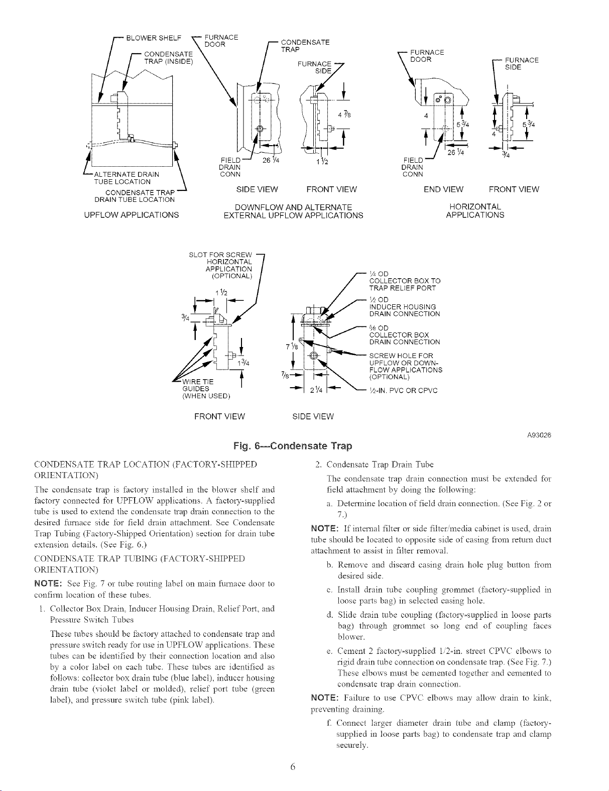
Fig. 6--Condensate Trap
71/8
l
FIELD --
DRAIN
CONN
END VIEW FRONT VIEW
COD
COLLECTOR BOX TO
TRAP RELIEF PORT
_OD
INDUCER HOUSING
DRAIN CONNECTION
'_OD
COLLECTOR BOX
DRAIN CONNECTION
SCREW HOLE FOR
UPFLOW OR DOWN-
FLOW APPLICATIONS
(OPTIONAL)
Y2-1N. PVC OR CPVC
¾
HORIZONTAL
APPLICATIONS
A93026
CONDENSATE TRAP LOCATION (FACTORY-SHIPPED
ORIENTATION)
The condensate trap is _lactory installed in the blower shelf and
_%cto*yconnected for UPFLOW applications A factow-supplied
tube is used to extend the condensate trap drain connection to the
desired furnace side for field drain attachment See Condensate
Trap Tubing (Factory=Shipped Orientation) section _br drain tube
extension details, (See Fig 6)
CONDENSATE TRAP TUBING (FA(TORY-SHIPPED
ORIENTATION)
NOTE: See Fig 7 or tube roudng label on main flul_ace door to
confirm tocation of these tubes
l. (ollector Box Drain, Inducer Housing Drain, Relief Pro1, and
Pressure Switch Tubes
These robes should be factory attached to condensate trap and
pressure switch tea@ for use in UPFLOW applications. These
robes can be identified by their connection location and also
by a color label on each robe. These robes are identified as
_bllows: collector box drain robe (blue label), inducer housing
&ain robe (violet label or molded), relief port tube (green
label), and pressure switch robe (pink label).
2. (ondensate Trap Drain Tube
The condensate trap drain connection must be extended for
field attachment by doing the ibllowing:
a Detemine location of field drain connection (See Fig. 2 or
7)
NOTE: If internal filter or side filter media cabinet is used, &ain
robe should be located to opposite side of casing fiom remm duct
attachment to assist in filter removal
b. Remove and discard casing drain hole plug button from
desired side.
c Install &ain robe coupling grommet (factow-supplied in
loose parts bag) in selected casing hole.
d. Slide &ain robe coupling (fi_ctory=supplied in loose parts
bag) through grommet so tong end of coupling _i_ces
blower.
e Cement 2 factory=supplied 1/2-in. street CPVC elbows to
rigid &ain tube connection on condensate trap (See Fig. 7)
These elbows must be cemented together and cemented to
condensate trap &ain connection.
NOTE: Failure to use CPVC elbows may allow &ain to kink,
preventing draining.
£ Connect larger diameter drain tube and clamp (factory-
supplied in loose parts bag) to condensate trap and clamp
securely,
COLLECTOR
DRAIN TUBE (BLUE
& WHITE STRIPED)
COLLECTOR
TUBE (PINK)
(MOLDED) DRAIN
TUBE (BEHIND
COLLECTOR BOX
DRAIN TUBE)
DRAIN TUBE (BLUE)
COLLECTOR BOX
TUBE (GREEN)
FACTORY-SUPPLIED
DRAIN TUBE
COUPLING (LEFT
DRAIN OPTION)
FIELD-INSTALLED
FACTORY-SUPPLIED
DRAIN TUBE
FACTORY-SUPPLIED
//2 -IN CPVC STREET
LEFT DRAIN OPTION
PLUG
CAP
FIELD-INSTALLED
ELBOWS (2) FOR
FIELD-INSTALLEE
FACTORY-SUPPLIED
DRAIN TUBE
COUPLING (RIGHT
DRAIN OPTION)
DRAIN TUBE (BLUE
& WHITE STRIPED)
COLLECTOR BOX
TUBE (PINK)
COLLECTOR BOX
TUBE (GREEN)
COLLECTOR BOX
DRAIN TUBE (GREEN)
TRAP
HOUSING
DRAIN TUBE
(VIOLET)
©
O O
A94213
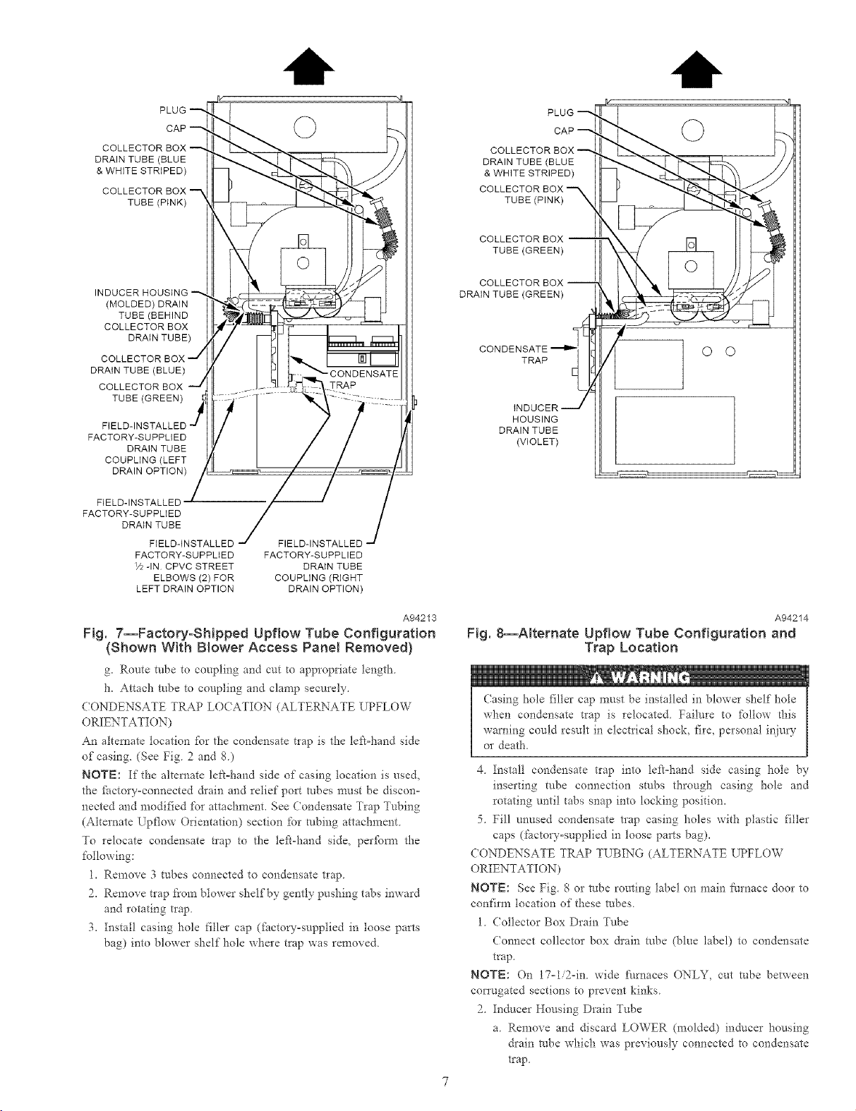
Fig. 7--Factory-SNpped Upflow Tube Configuration
(Shown With Blower Access Pane_ Removed}
g. Route tube to coupling and cut [o appropriate length
1",.Attach robe to coupling and clamp securely.
CONDENSATE TRAP LO(ATION (ALTERNATE UPFLOW
ORIENTATION)
An alteraate location _Pr the condensate tlap is the left=hand side
of casing. (See Fig 2 and 8)
NOTE: If the alternate lek=hand side of casing location is used,
the _i_ctory=cormected &ain and relief port robes must be discon=
nected and modified fo* attachment. See Condensate Trap Tubing
(Alternate Upflow Orientation) section for tubing attachment
To relocate condensate t_ap to the tef_-hand side, perfbm_ the
following:
1. Remove 3 tubes connected to condensate trap.
2. Remove trap from blower shelf by gently pushing tabs inward
and rotating t_ap.
3. Instal! casing hole filler cap ditctow-supplied in loose parts
bag) into blower shelf hole where trap was removed.
A94214
Fig. 8--ARernate Upflow Tube Configuration and
Trap Location
(using hole filler cap must be installed in blower shelf hole
when condensate trap is relocated. Failure to tbllow d_is
warning could result in electrical shock, fire, personal injury
or death.
4. Install condensate trap into left=hand side casing hole by
inserting tube connection stubs through casing hole and
rotating until tabs snap into locking position.
5. Fill unused condensate trap casing holes with plastic filler
caps (factory=supplied in loose parts bag).
CONDENSATE TRAP TUBING (ALTERNATE UPFLOW
ORIENTATION)
NOTE: See Fig. 8 or robe routing label on main Nrnace door to
confirm location of these robes.
1. Collector Box Drain Tube
Connect collector box &ain robe (blue label) to condensate
trap.
NOTE: On 17=1/2=in. wide fi/rnaces ONLY, cut robe between
con'ugated sections to prevent kinks.
2. Inducer Honsing Drain Tube
a. Remove and discard LOWER (molded) inducer housing
drain robe which was previously connected to condensate
trap
COLLECTOR BOX
DRAIN TUBE (BLUE)
PLUG
COLLECTOR BOX
TUBE (GREEN)
CA_
O O
TUBE (GREEN)
DRAIN TUBE (BLUE)
TUBE (PINK)
COLLECTOR
DRAIN TUBE (BLUE
& WHITE STRIPED)
EXTENSION TUBE
TRAP
©
INDUCER HOUSING
DRAIN TUBE(VIOLET) ._
A94215
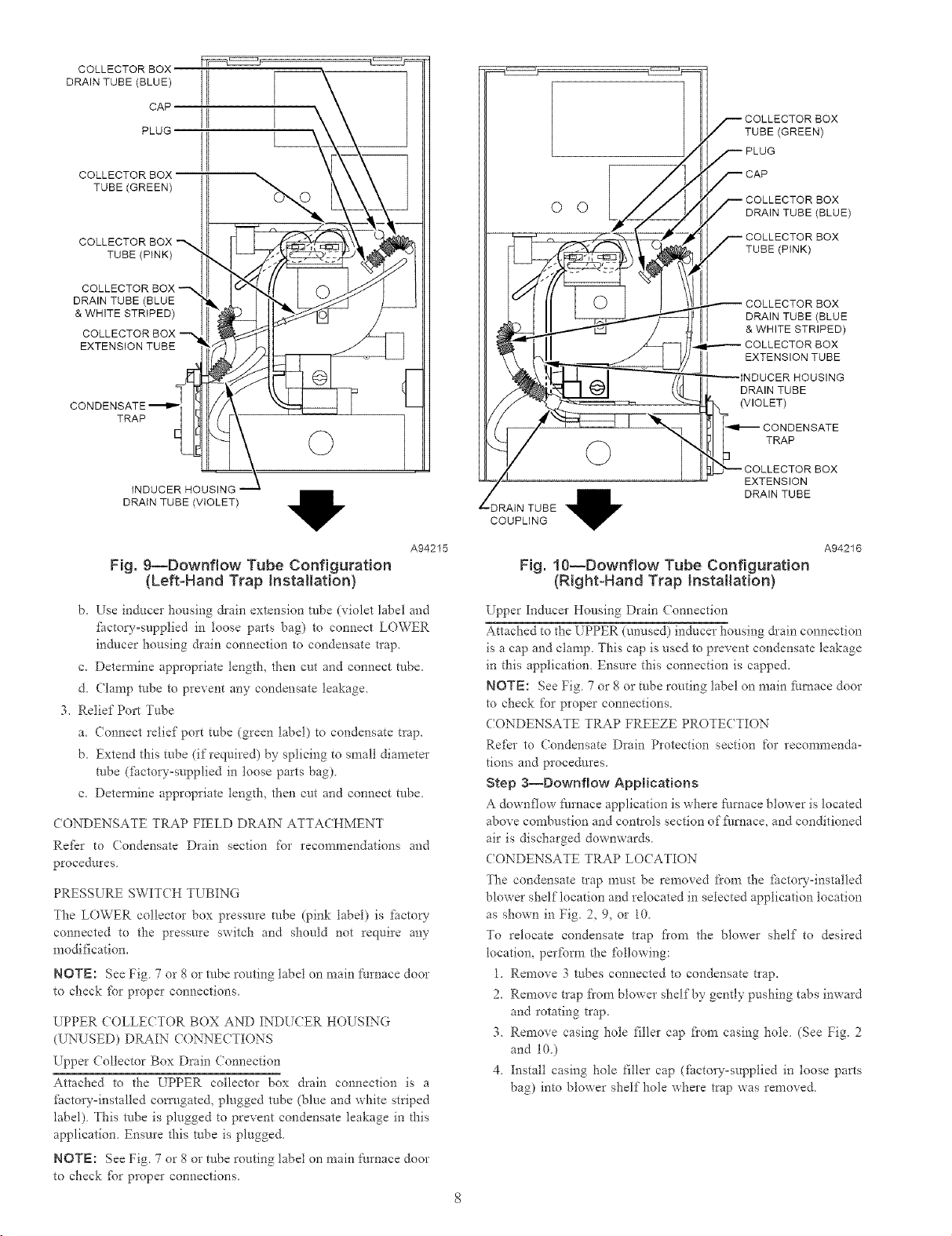
Fig. 9--Downflow Tube Configuration
(Left-Hand Trap Installation)
b. Use inducei housing &ain extension tube (violet label and
thctow-supplied in toose parts bag) to connect LOWER
inducer housing &ain connection to condensate trap.
c. Detem_ine appropriate tength, then cut and connect tube.
d. Ctamp robe to prevent any condensate leakage.
3. Relief Port Tube
a. (onnect relief port tube (green label) to condensate trap.
b. Extend this tube (if required) by splicing to small diameter
tube (fhctowosupplied in toose parts bag)
c. Detem_ine appropriate tength, then cut and connect tube.
(ONDENSATE TRAP FIELD DRAIN ATTACHMENT
Refkr to Condensate Drain section for recommendations and
procedures
PRESSURE SWITCH TUBING
The LOWER collector box pressure tube (pink 1abel) is factor
connected to the pressure switch and should not require any
modification.
NOTE: See Fig 7 or g or tube routing label on main [:umace door
to check fbr proper connections.
UPPER COLLECTOR BOX AND INDUCER HOUSING
(UNUSED) DRAIN CONNE(TIONS
Upper Collector Box Drain (7onnection
Attached to the UPPER collector box drain connection is a
fhctory=installed corn/gated, plugged robe (blue and white striped
label) This robe is plugged to prevent condensate leakage in this
application Ensure this robe is plugged
NOTE: See Fig. 7 or 8 or robe routing label on main furnace door
to check fbr proper connections.
TUBE (PINK)
COLLECTOR BOX
DRAIN TUBE (BLUE
& WHITE STRIPED)
COLLECTOR BOX
EXTENSION TUBE
DRAIN TUBE
(VIOLET)
CONDENSATE
TRAP
EXTENSION
DRAIN TUBE
'DRAIN TUBE
COUPLING
A94216
Fig. 10--Downflow Tube Configuration
(Right=Hand Trap Insta{lation)
Upper Inducer [Iousing Drain (onnection
Attached to the UPPER (unused) inducer housing &ain connection
is a cap and clamp. This cap is used to prevent condensate leakage
in this application. Ensure this connection is capped.
NOTE: See Fig. 7 or 8 or tube routing label on main fhrcmce door
to check fbr proper connections.
CONDENSATE TRAP FREEZE PROTECTION
Refer to Condensate Drain Protection section for recommenda-
tions and procedures.
Step 3--Downflow Applications
A downflow fm'nace application is where furnace blower is located
above combustion and controls section of furnace, and conditioned
air is discharged downwards.
CONDENSATE TRAP LOCATION
The condensate trap must be removed ti"om the fhctow-installed
blowe* shelf'location and relocated in selected application tocation
as shown in Fig. 2, 9, or 10
To relocate condensate trap fi'om the blower shelf to desired
location, per%tin the following:
1. Remove 3 tnbes connected to condensate t_ap.
2. Remove trap from blower shelf by gently pushing tabs inward
and rotating trap.
3. Remove casing hole filler cap flora casing hole (See Fig. 2
and 10.)
4. Install casing hole filler cap (fhctow-supplied in toose parts
bag) into blower shelf hole where trap was removed
Casing hole filler cap must be installed in blower shelf hole
when condensate trap is relocated. Failure to %llow this
warning could result in electrical shock, fire, personal injury
or death.
5. Install condensate trap into left-hand side casing hole by
inserting tube connection stubs through casing hole and
rotating until tabs snap into locking position,
6. Fill unused condensate trap casing holes with plastic filler
caps (flactory°supplied in toose parts bag)
CONDENSATE TRAP TUBING
NOTE: See Fig. 9 or 10 or robe routing label on main fm'nace
door to check for proper connections
1. (ollector Box Drain Tube
a. Remove fi_ctory=installed plug flora LOWER collector box
drain robe (blue and white striped label).
b. Instal! removed clamp and plug into UPPER collector box
&ain tube Cblue label) which was connected to condensate
t_ap.
c. Connect LOWER collector box drain connection to con=
densate tlap.
(1.) Condensate Trap Located on Left Side of Casing
(aj Connect LOWER collector box &ain robe (blue
and white striped label) to condensate trap. Tube
does not need to be cut.
Cb.) Clamp tube to prevent any condensate leakage.
CZ) Condensate Trap Located on Right Side of (asing
Caj Install drain tube coupling (fhctow-supplied in
loose parts bag) into collector box drain robe
(blue and white striped label) which was previ=
ously plugged.
Cb.) Connect larger diameter &ain robe (g_ctory=
supplied in loose parts bag) to &ain tube cou=
piing, extending collector box drain robe for
connection to condensate trap
Cc) Route extended collector box &ain tube between
gas valve and inlet housing as shown in Fig. 10.
Cd) Dete*mine app*opriate length and cut
(e) Connect to condensate t*ap
(f.) Clamp tube to prevent any condensate leakage.
2. Inducer Housing Drain Tube
a. Remove titctoEv=installed cap and clamp from LOWER
inducer housing drain connection.
b. Remove and discard UPPER (molded) indocer housing
&ain robe which was previously connected to condensate
tlap.
c Install cap and clamp on UPPER inducm housing &ain
connection where molded &ain robe was removed.
d. Lse inducer housing &ain robe (violet 1abel and factory=
supplied in loose parts bag) to connect LOWER inducer
housing &ain connection to the condensate trap
e. (onnect inducer housing drain connection to condensate
trap.
Cij (ondensate Trap Located on Left Side of (asing
Ca.) Detem_ine appropriate lengd_ and cut.
(b.) Connect robe to condensate trap.
(c.) Clamp robe to prevent any condensate leakage.
(20 (ondensate Trap Located on Right Side of Casing
Ca.) Route inducer housing drain robe (violet label)
directly from inducer housing to condensate trap.
Cb) Determine appropriate length and cut
(c.) (onnect robe to condensate trap.
C&) Clamp robe to prevent any condensate leakage.
3. Relief Port Tube
Re_kr to Pressure Switch Tubing section ibr connection
procedure.
CONDENSATE TRAP FIELD DRAIN ATTACHMENT
Re_kr to Condensate Drain section %r recommendations and
procedures.
PRESSURE SWITCH TUBING
One collector box pressure tube (pink label) is factory connected to
the pressure switch %r use when furnace is installed in UPFLOW
or HORIZONTAL LEFT applications. This robe MUST be dis-
connected and used ibr the condensate trap relief port robe. The
other collector box pressure robe (green label) which was ifctory
connected to the condensate trap relief port connection MUST be
connected to the pressure switch in DOVv_FLOW or HORIZON-
TAL RIGHT applications.
NOTE: See Fig. 9 or 10 or robe routing label on main furnace
door to check %r proper connections.
Relocate tubes as described below.
1. Disconnect collector box pressure robe (pink label) attached to
pressure switch.
2. Extend collector box pressure robe Cgreen label) which was
previously connected to condensate trap relief port connection
by splicing to small diameter robe Cflactou-supptied in loose
parts bag).
3. (onnect collector box pressure robe (green label) to pressure
switch connection labeled COLLECTOR BOX.
4. Extend collector box pressure tube (pink label) which was
previously connected to pressure switch by splicing to remain-
ing small diameter tube Cfactow-supplied in loose parts bag).
5 Route this extended tube {pink label) to condensate trap relief
port connection.
6. Determine appropriate length, cut, and connect robe.
7. (lamp robe to relief port connection.
CONDENSATE TRAP FREEZE PROTECTION
Refer to (ondensate Drain Protection section for recommenda-
tions and procedures.
Step 4--Horizontal Left (Supply°Air Discharge)
Applications
A horizontal te_ _hmace application is where furnace blower is
located to the right of combustion and controls section of _hrnace,
and conditioned air is discharged to the left.
Local codes may require a drain pan under entire furnace and
condensate trap when a condensing thmace is used in an attic
application or over a finished ceiling.
NOTE: In Canada, installations shall be in accordance with
cmTent NSCNGPI( and/or local codes
CONDENSATE TRAP LO(ATION
The condensate trap must be removed from the fi_ctory=installed
blower shelf location and relocated in selected application location
as shown in Fig 2 or 11.
PLUG --
AUXILIARY "J" BOX --_ \ ] f-- COLLECTOR BOX
TRAP X\\ XX \ TUBE(GREEN)
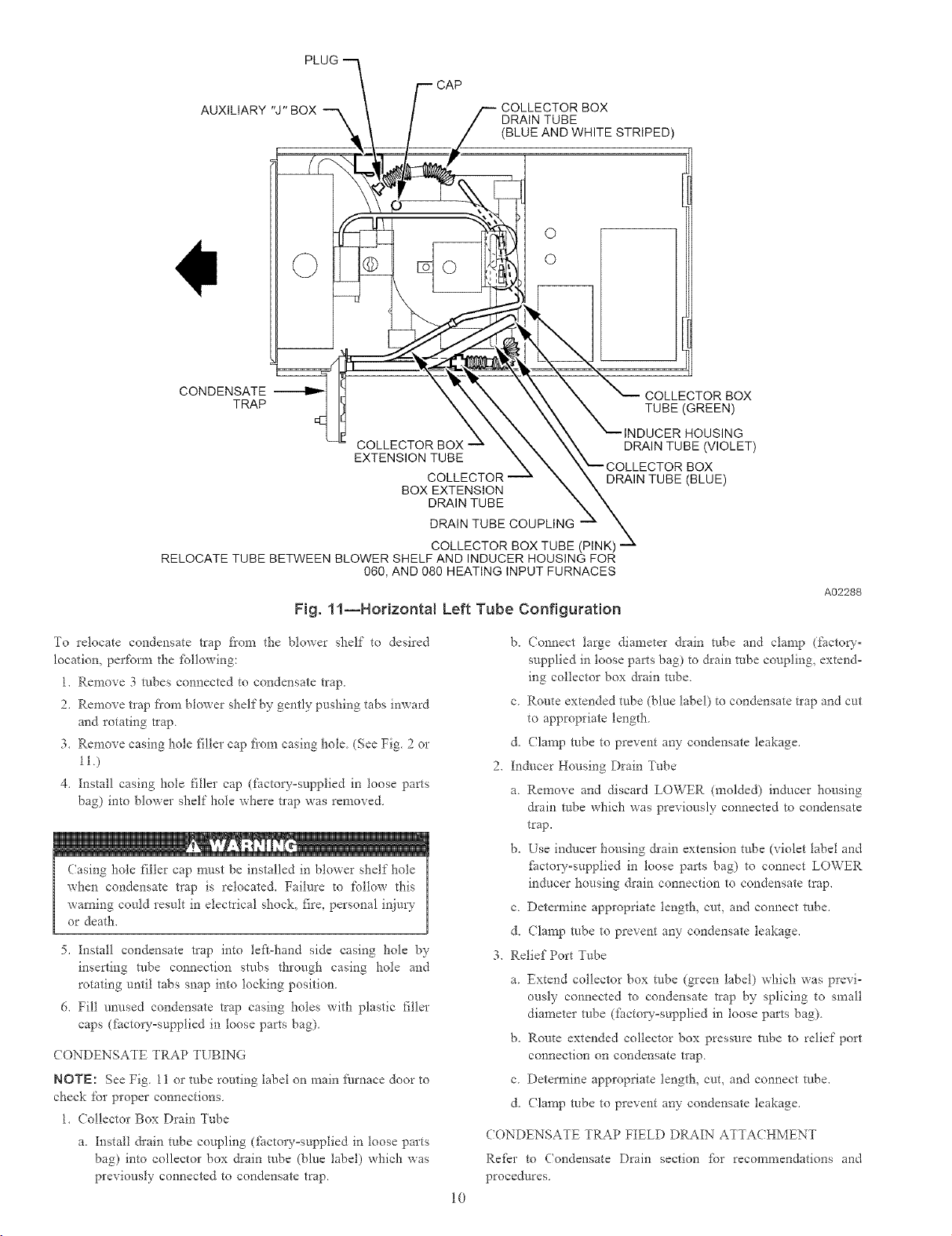
RELOCATE TUBE BETWEEN BLOWER SHELF AND INDUCER HOUSING FOR
\ \ ] / DRAIN TUBE
_/ / / (BLUE AND WHITE STRIPED)
t Ii_ \ \ \ \\ ""--INDUCER HOUSING
COLLECTOR BOX _ & _ \\ DRAIN TUBE (VIOLET)
EXTENSION TUBE X X X _COLLECTOR BOX
060, AND 080 HEATING INPUT FURNACES
V CAP
.... C_(D_-_L_E.C_T.O_R_ N \ DRAIN TUBE (BLUE)
BOX EXTENSION N \
DRAIN TUBE X X
DRAIN TUBE COUPLING _
COLLECTOR BOX TUBE (PINK)
Fig. 11--Horizontal Left Tube Configuration
x
A02288
To relocate condensate trap from the blower shelf to desired
location, perform the tbllowing:
1 Remove 3 robes connected to condensate trap
2 Remove trap fiom blower shelf by gently pushing tabs inward
and rotating trap
3 Remove casing hole filler cap fiom casing hole (See Fig 2 or
11.)
4. Install casing hole filler cap (facto_ supplied in loose parts
bag) into blower shelf hole where trap was removed
Casing hole filler cap must be installed in blower shelf hole
when condensate tIap is relocate& Failure to follow this
warning could result in electrical shock, fire, personal injury
or death
5. Install condensate trap into tell hand side casing hole by
inserfing robe connection stubs through casing hole and
rotating until tabs snap into locking position
6 Fill unused condensate trap casing holes with plastic filler
caps (ihctoryosupptied in loose parts bag)
CONDENSATE TRAP TUBING
NOTE: See Fig 11 or robe routing label on main ihrnace door to
check for proper connections
1 Collector Box Drain Tube
a. Install &ain tube coupling (fhctovosupplied in loose parts
bag) into collector box drain tube (blue label) which was
previously connected to condensate trap
b (onnect large diameter drain tube and clamp (factory
supplied in loose parts bag) to drain robe coupling, extend
ing collector box &ain robe
c Route extended tube (blue label) to condensate nap and cut
to appropriate lengfl_
d (lamp robe to prevent any condensate leakage
2 Inducer Housing Drain Tube
a Remove and discard LOWER (molded) inducer housing
drain robe which was previously connected to condensate
trap
N
b Use inducer housing &ain extension tube (violet label and
ihctoryosupplied in loose parts bag) to connect LOWER
inducer housing &ain connection to condensate trap
c Determine appropriate length, cut, and connect tube
d (lamp robe to prevent any condensate leakage
3 Relief Port Tube
a Extend collector box robe (green label) which was previ
ously connected to condensate trap by splicing to small
diameter robe (fhctoryosupplied in loose parts bag)
b Route extended collector box pressure robe to relief port
connection on condensate trap
c Determine appropriate length, cut, and connect robe
& Clamp robe to prevent any condensate leakage
CONDENSATE TRAP FIELD DRAIN ATTACHMENT
Ref?r to (ondensate Drain section fbr recommendations and
procedures
10
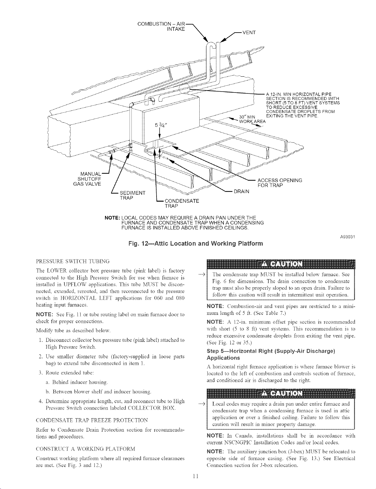
INTAKE
A 12-1N MIN HORIZONTAL PIPE
SECTION IS RECOMMENDED WITH
SHORT (5 TO 8 FT) VENT SYSTEMS
TO REDUCE EXCESSIVE
CONDENSATE DROPLETS FROM
EXITING THE VENT PIPE
SHUTOFF
GAS VALVE
SEDIMENT
TRAP
CONDENSATE
TRAP
NOTE: LOCAL CODES MAY REQUIRE A DRAIN PAN UNDER THE
FURNACE AND CONDENSATE TRAP WHEN A CONDENSING
FURNACE IS INSTALLED ABOVE FINISHED CEILINGS.
Fig. 12--Attic Location and Working Platform
PRESSL RE SWIT(H TL BING
The LOWER collector box pressure tube (pink label) is factor
connected to the High Pressure Switch fbr use when _hrnace is
installed in UPFLOW applications. This robe MUST be discon-
nected, extende& rerouted, and then reconnected to the pressure
switch in HORIZONTAL LEFT applications _br 050 and 080
heating input ihrnaces.
NOTE: See Fig. 11 or tube routing label on main Nrnace door to
check for proper connections.
Modif}" robe as described below.
1. Disconnect collector box pressure tube (pink label) attached to
High Pressure Switch.
2. Use smaller diameter tube (factory-supplied in loose parts
bag) to extend robe disconnected in item 1
3. Route extended robe:
a. Behind inducer housing.
b. Between blower shelf and inducer housing.
4. Detem_ine appropriate length, cut, and reconnect tribe to High
Pressure Switch connection labeled COLLE(TOR BOX.
ACCESS OPENING
FOR TRAP
DRAIN
A93031
NOTE: (ombustion=air and vent pipes are restricted to a mira-
mum length of 5 ft. (See Table 7.)
NOTE: A 12-in. minimum offset pipe section is recommended
with short (5 to 8 ft) vent systems. This recommendation is to
reduce excessive condensate droplets flora exiting the vent pipe.
(See Fig. 12 or 35.)
Step 5--Horizontal Right (SupplyoAir Discharge)
Applications
A horizontal right furnace application is where t:urnace blowei is
located to d_e left of combustion and conhols section of _i/rnace,
and conditioned air is discharged to the right.
CONDENSATE TRAP FREEZE PROTECTION
Re_kr to Condensate Drain Protection section %r recommenda-
tions and procedures,
CONSTRUCT A WORKING PLATFORM
(onstruct working platfbm_ where all required [k_rnace clearances
are met. (See Fig 3 and 12)
NOTE: In (anada, installations shall be in accordance with
cun'ent NSCNGPIC Installation Codes and/or local codes
NOTE: The auxiliaLy junction box (J-box) MUST be relocated to
opposite side of furnace casing. (See Fig. 13.) See Electrical
Connection section for J-box relocation.
11
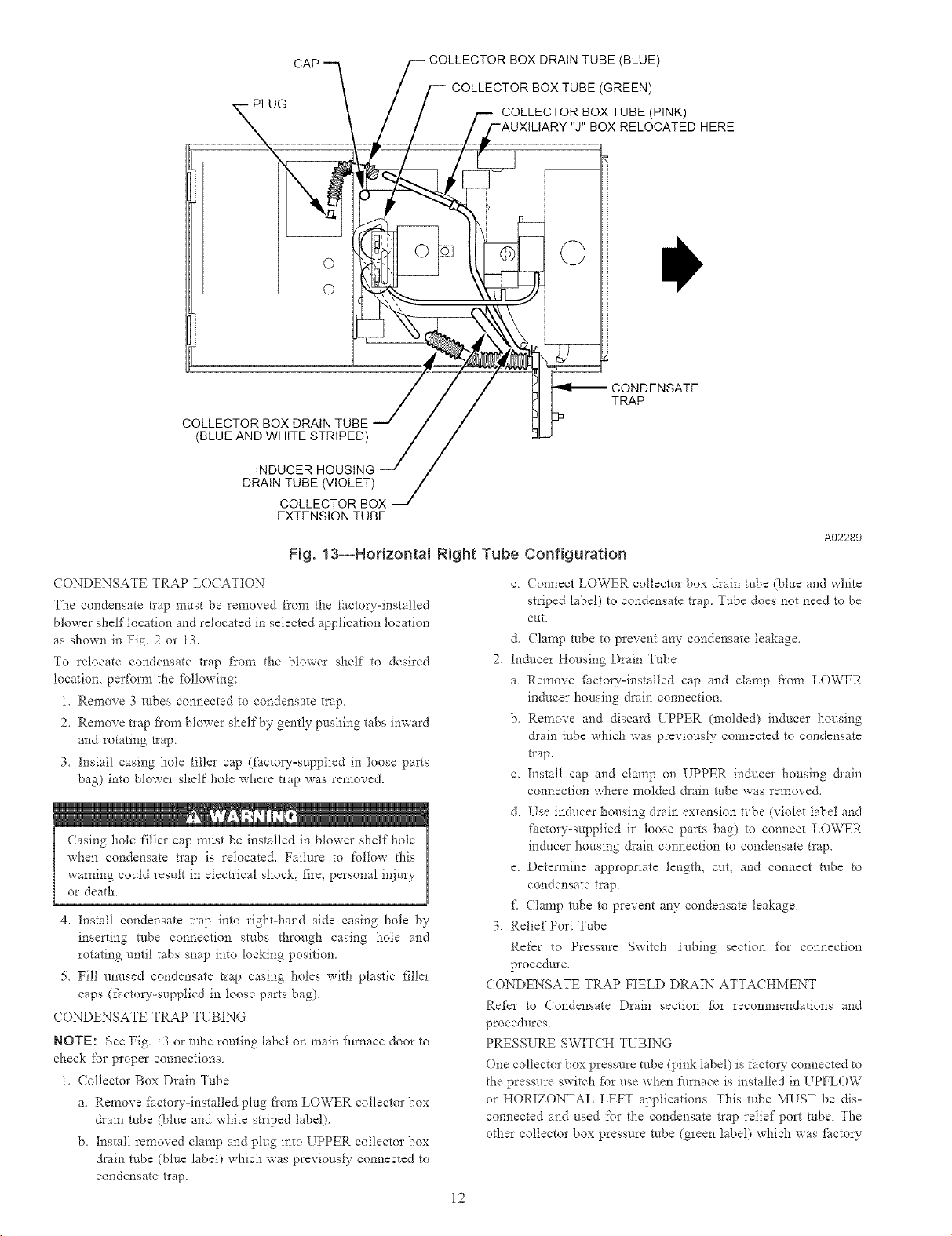
CAP
O
O
COLLECTOR BOX DRAIN TUBE
(BLUE AND WHITE STRIPED)
DRAIN TUBE (VIOLET)
COLLECTOR BOX
EXTENSION TUBE
Fig. 13--Horizontal Right Tube Configuration
CONDENSATE TRAP LOCATION
The condensate tlap n-rest be removed from the factow-installed
blower shelf location and relocated in selected application location
as shown in Fig. 2 or 13.
To relocate condensate trap from the blower shelf to desired
location, perfom_ the [bllowing:
1. Remove 3 robes connected to condensate trap.
2. Remove trap fiorn blower shelf by gently pushing tabs inward
and rotating trap.
3. Install casing hole filler cap (factory-supplied in loose parts
bag) into blower shelf hole where trap was removed.
Casing hole filler cap must be installed in blower shelf hole
when condensate trap is relocated. Failure to follow this
warning could result in electrical shock, fire, personal injury
or death.
4. Install condensate trap into rightohand side casing hole by
inserting robe connection stubs through casing hole and
rotating until tabs snap into locking position
5. Fill unused condensate trap casing holes with plastic filler
caps (fi_ctoryosupplied in loose parts bag)
(ONDENSATE TRAP TUBING
NOTE: See Fig. 13 or robe routing label on main fhrnace door to
check for proper connections.
1. (ollector Box Drain Tube
a. Remove fi_ctoryoinstalled plug fiom LOWER collector box
&ain robe (blue and white striped label).
b. Install removed clamp and plug into UPPER collector box
&ain robe (blue label) which was previously connected to
condensate trap.
BOX DRAIN TUBE (BLUE)
COLLECTOR BOX TUBE (GREEN)
-- COLLECTOR BOX TUBE (PINK)
BOX RELOCATED HERE
CONDENSATE
TRAP
A02289
c (onnect LOWER collector box drain robe (blue and white
striped label) to condensate trap Tube does not need to be
cut.
d. Clamp robe to prevent any condensate leakage.
2. Inducer Housing Drain Tube
a. Remove fhctoryoinstalled cap and clamp from LOWER
inducer housing drain connection.
b. Remove and discard UPPER (molded) inducer housing
&ain robe which was previously connected to condensate
tlap.
c. Install cap and clamp on UPPER inducer housing &ain
connection where molded &ain robe was removed.
d. Use inducer housing &ain extension robe (violet label and
factoryosupplied in loose parts bag) to connect LOWER
inducer housing &ain connection to condensate trap.
e. Detem_ine appropriate length, cuk and connect robe to
condensate trap.
f\ (lamp robe to prevent any condensate leakage.
3. Relief Port Tube
Refer to Pressure Switch Tubing section for connection
procedure.
CONDENSATE TRAP FIELD DRAIN ATTACHMENT
Refkr to Condensate Drain section for recommendations and
procedures.
PRESSURE SWITCH TUBING
One collector box pressure tube (pink label) is J:ilctory connected to
the pressure switch fbr use when ft_rnace is installed in UPFLOW
or HORIZONTAL LEFT applications. This tube MUST be dis-
connected and used for the condensate trap relief port robe. The
other collector box pressure robe (green label) which was fhcto_
12
connected to the condensate trap relief port connection MUST be
connected to the pressure switch in DOWNFLOW or HORIZON°
TAL RIGHT applications,
ROTE: See Fig. 13 or tube routing 1abel on main fhmace door to
check for proper connections
Relocate tubes as described below,
1, Disconnect collector box pressu*e tube (pink 1abet) attached to
pressure switch.
2. Extend collector box pressure robe (green label) which was
previously connected to condensate trap relief port connection
by splicing to small diameter robe (factow-supplied in loose
parts bag).
3. (onnect collector box pressure tube (green label) to pressure
switch connection labeled COLLE(TOR BOX.
4. Use remaining small diameter tube (factory-supplied in loose
parts bag) to extend collector box pressure robe (pink label)
which was previously connected to pressure switch.
5. Route this extended robe (pink label) to condensate trap relief
port connection.
6. Detem_ine appropriate length, cut, and connect robe.
7. Clamp robe to relief port connection.
CONDENSATE TRAP FREEZE PROTECTION
Re*kr to Condensate Drain Protection section for recommenda=
tions and procedores.
CONSTRUCT A WORKING PLATFORM
Construct working platfbrm where all required [:urnace clearances
are met, (See Fig. 3 and 12.)
--€
The condensate trap MUST be installed below fimaace See
Fig. 6 _br dimensions. The drain connection to condensate
trap must also be properly sloped to an open &ain Failure to
follow this caution will result in intermittent unit operation.
ROTE: Combustion-air and vent pipes are restricted to a mira°
mum length of 5 ft. (See Table 7.)
ROTE: A 12-in. n_ininlum offset pipe section is recommended
with short (5 to 8 ft) vent systems. This recommendation is to
reduce excessive condensate &oplets fi'om exiting the vent pipe.
(See Fig. 12 or 35.)
LOCATION
Step l--General
This _hmace must
* be installed so the electrical components are protected from
water.
* not be installed directly on any combustible material other than
wood flooring (refer to SAFETY CONSIDERATIONS).
* be located so combustion-air and vent pipe maximum lengths
are not exceeded. Re_kr m Table 7.
* be located where available electric power and gas supplies meet
specifications on the furnace rating plate.
* be attached to an air distribution system and be located as close
to the center of the distribution system as possible. Re_r to Air
Ducts section.
* be provided with ample space for servicing and cleaning.
Always comply with minimum fire protection clearances
shown on the Nrnace clearance-to-combustibles label. (See
Fig. 3.)
This Nmace may be located in a confined space without special
provisions for dilution or ventilation air.
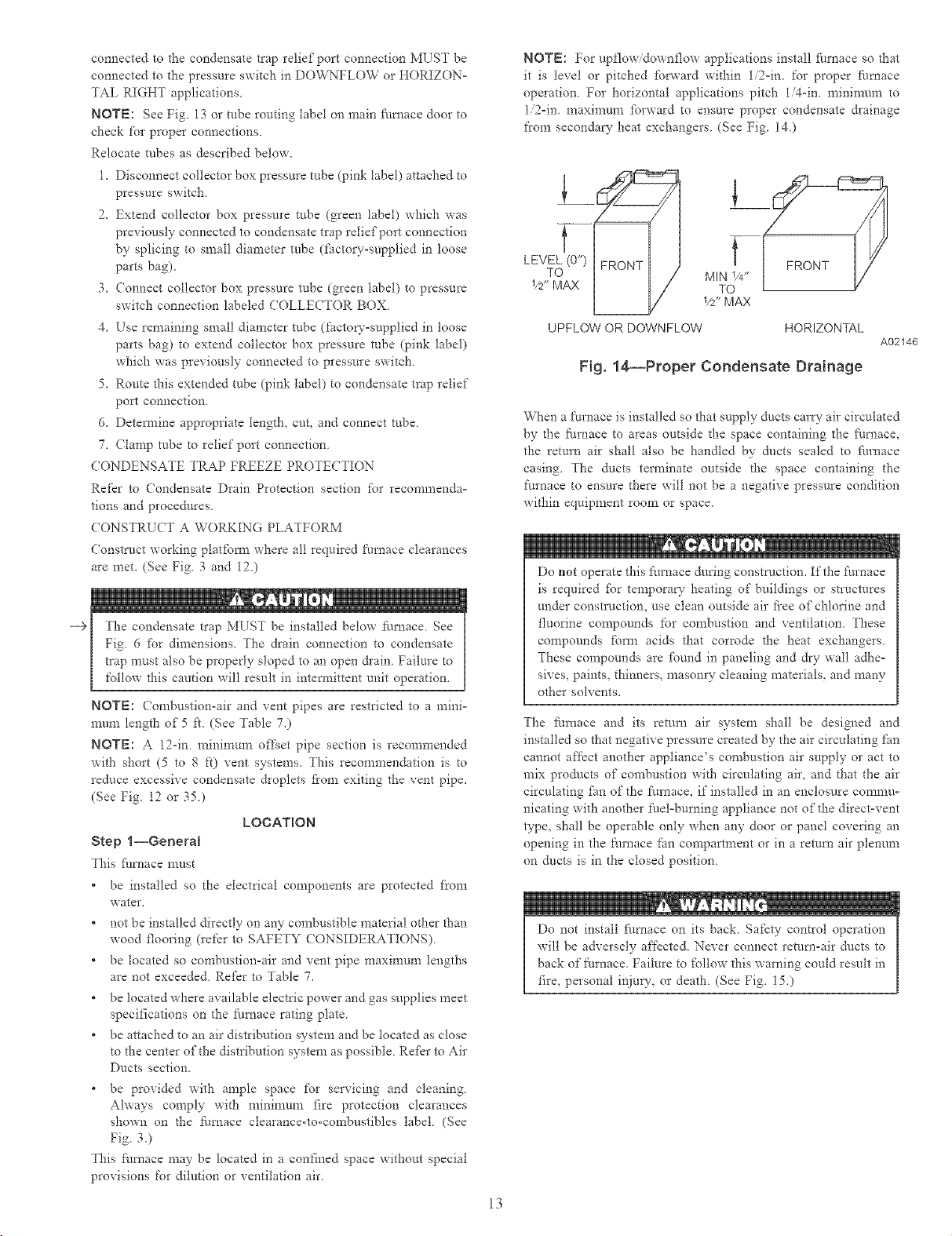
NOTE: For upflowidownflow applications install fi_.rnace so that
it is level or pitched fbrward within 1/2=in. for proper fitmace
operation. For horizontal applications pitch 1/4-in. minimum to
1/2=in maximum forward to ensure proper condensate &ainage
from secondaw heat exchangers (See Fig. 14)
LEVEL (0")
TOL_ MIN 1/4"
1/2" MAX TO
UPFLOW OR DOWNFLOW HORIZONTAL
_/2"MAX
Fig. 14--Proper Condensate Drainage
When a t\N'nace is installed so that supply ducts car W air circulated
by d_e furnace to areas outside the space containing the flu_ace.
the return air shall also be handled by ducts sealed to filrnace
casing. The ducts terminate outside the space containing the
furnace to ensure there will not be a negative pressure condition
within equipment room or space.
Do not operate this fitrnace during construction. If the furnace
is required _br temporary heating of buildings or structures
under constrllction, use clean outside air fl'ee of chlorine and
fluorine compounds for combustion and ventilation. These
compounds fbma acids that corrode tiae heat exchangers
These compounds are tbund in paneling and dw- wai! adiae=
sires, paints, thinners, masom'y cleaning materials, and many
other solvents.
The furnace and its return air system shall be designed and
installed so that negative pressure created by the air circulating fan
cannot affect another appliance's combustion air supply or act to
mix prodtlcts of combustion with circulating air, and that the air
circulating _hn of the furnace, if installed in an enclosure comnm-
nicating with another fuel-burning appliance not of the direct-vent
type, shall be operable only when any door or panel covering an
opening in the 5m_ace fan compartment or in a return air plenum
on ducts is in the closed position.
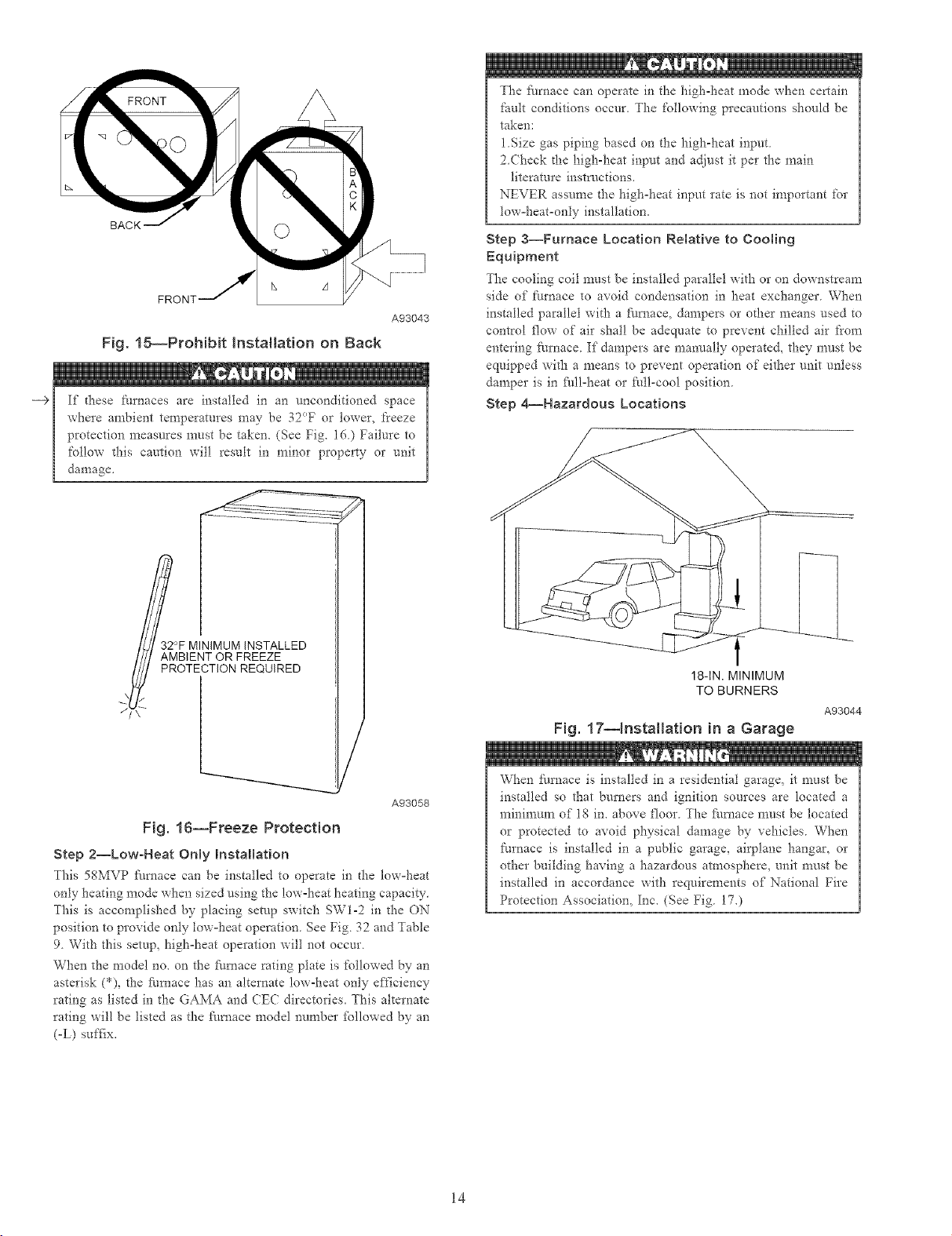
Do not install fllrnace on its back. Safety control operation
will be adversely affected. Never connect return-air ducts to
back of furnace. Failure to _bllow this warning could result in
fire, personal injury, or death (See Fig. 15.)
13
A02146
BACK
Fig. 15--Prohibit Installation on Back
,_ , t 1
--€
If d-*ese furnaces are installed in an unconditioned space
where ambient temperatures may be 32°F or lower, t'reeze
protection measures must be taken. (See Fig. 16) Failure to
follow d_is caution will result in minor property or unit
damage.
A93043
The fi_rnace can operate in the high-heat mode when certain
fault conditions occur. The following precautions should be
taken:
1Size gas piping based or* the high-heat input
2 (hock dte high-heat input and adjust it per the main
literature instrnctions.
NEVER assume the high°heat input rate is not important for
tow°heat=only installation.
Step 3--Furnace Location Relative to Cooting
Equipment
The cooling coil must be installed parallel with or on downstream
side of furnace to avoid condensation in heat exchanger When
installed parallel with a filmace, dampers or other means used to
control flow of air shal! be adequate to prevent chilled air from
entering furnace If dampers are manually operated, they must be
equipped with a means to prevent operation of either unit unless
damper is in fidl=iaeat or full-cool position
Step 4--Hazardous Locations
°F MINIMUM INSTALLED
I//I AMBIENT OR FREEZE II
_/ PROTECTION REQUIRED II
A93058
Fig. 16--Freeze Protection
Step 2--Low-Heat Only mnstallation
7his 58MVP furnace can be installed to operate in [he low°heat
only heating mode when sized using the low°heat heating capacity.
This is accomplished by placing setup switch SW1-2 in the ON
position to provide only tow-heat operation. See Fig. 32 and Table
9. With this setup_ high=heat operation will not occur.
When the model no. or* the ft/mace rating plate is followed by an
asterisk (*), the fitmace has an alternate low-heat only efficiency
rating as listed in the GAMA and CEC directories. This alternate
rating will be listed as the fi/mace model number _bllowed by an
(-L) suffix.
18-1N. MINIMUM
TO BURNERS
A93044
Fig. 17--Installation in a Garage
When furnace is installed in a residential garage, it must be
installed so that burners and ignition sources are located a
mininmm of 18 in. above floor. The fi/mace must be located
or protected to avoid physical damage by vehicles. Wiaen
furnace is installed in a public garage, airplane hangar, or
other building having a hazardous atmosphere, unit must be
installed in accordance with requirements of National Fire
Protection Association, Inc. (See Fig. 170
14
mNSTALLATION
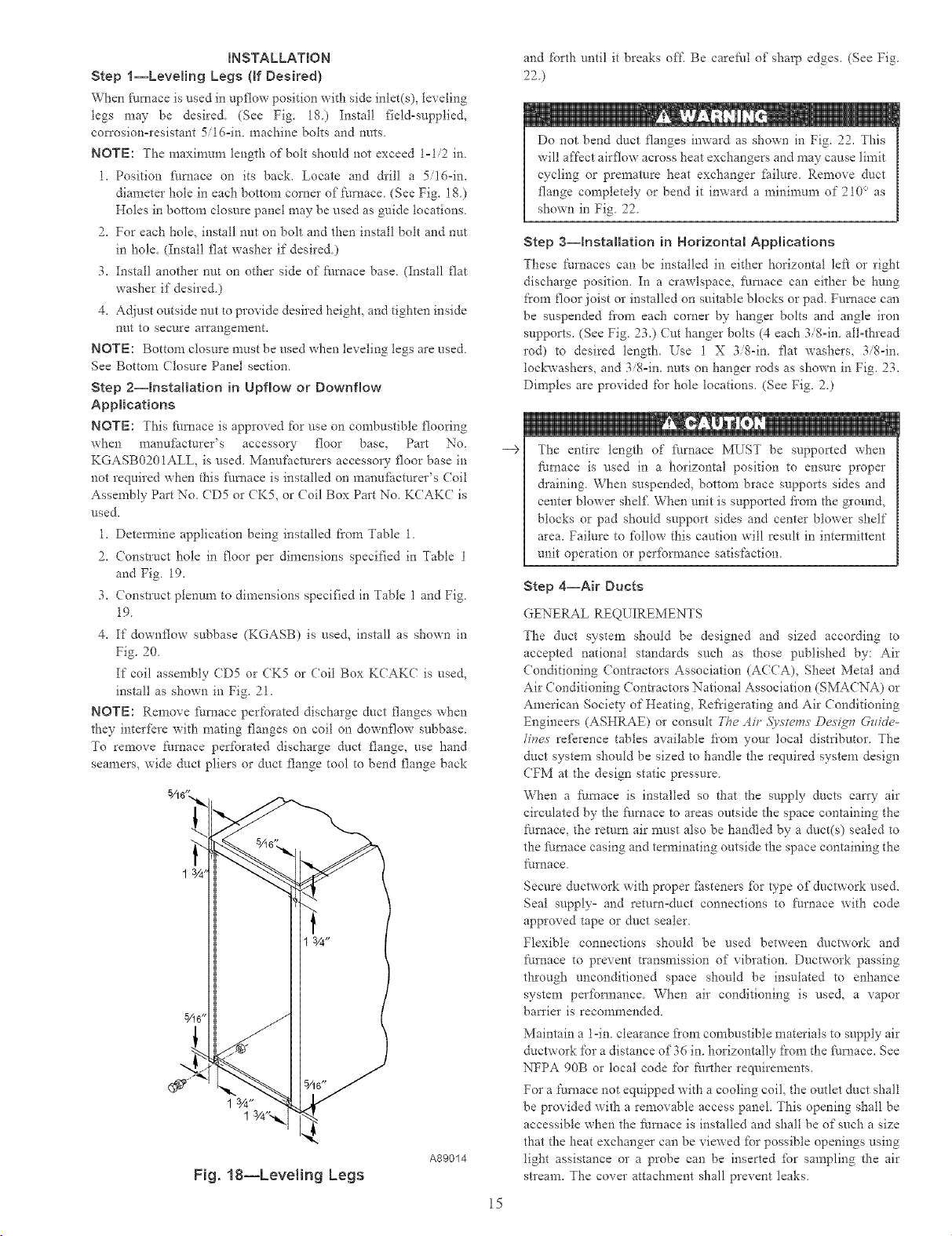
Step l--Leveling Legs (If Desired)
When f_lmace is need in upgow position with side inlet(s), leveling
togs may be desire& (See Fig. 18) Install field=supplied,
cmTosion=resistant 5716-in machine bolts arid nuts.
NOTE: The maximum length of bolt should not exceed 1=1/2 in.
1. Position ihmace on its back. Locate and dril! a 5/16=in.
diameter hole in each bottom corner of furnace. (See Fig. 1K)
Holes in bottom closure panel may be used as guide locations.
2. For each hole, install nut on bolt and then install bolt and nut
in hole. (Install flat washer if desired.)
3. Install another nut on other side of _i/rnace base. (Install flat
washer if desired.)
4. A({iust outside nut to provide desired height, and tighten inside
nut to secure arrangement.
NOTE: Bottom closure must be used when leveling legs are used.
See Bottom Closure Panel section.
Step 2--hstaHation in Upf!ow or Downflow
Applications
NOTE: This furnace is approved for use on combustible flooring
when manuf_cturer's accesso W floor base, Part No
KGASB0201ALL, is used. Manufacturers accessory floor base in
not required when this filmace is installed on manufhcmrer's (Toil
Assembly Part No. CD5 or CK5, or Coil Box Part No. KCAKC is
used.
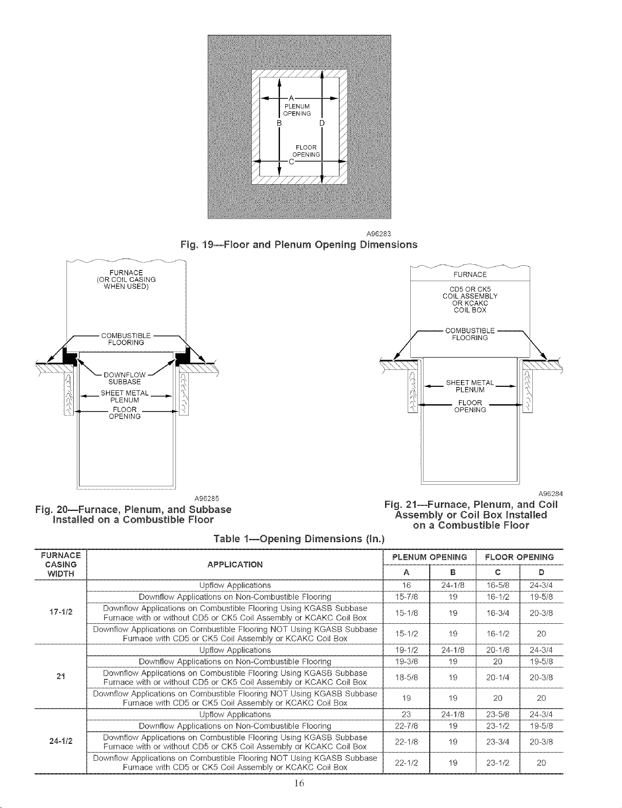
1. Detem_ine application being installed t'rom Table 1.
2. (onstruct hole in floor per dimensions specified in Table 1
and Fig. 19.
3. (onstruct plenum to dimensions specified in Table 1 and Fig.
19.
4. If downflow subbase (KGASB) is used, install as shown in
Fig. 20.
If coil assembly (D5 or CK5 or (Toil Box KCAKC is used,
install as shown in Fig. 21.
NOTE: Remove furnace perforated discharge duct ganges when
they interfere with mating flanges on coil on downflow subbase.
To remove Nrnace peribrated discharge duct flange, use hand
seamers, wide duct pliers or duct flange tool to bend flange back
A89014
Fig. 18--Leveling Legs
and %rth until it breaks off, Be careful of sharp edges, (See Fig.
22 )
Do not bend duct flanges inward as shown in Fig. 22, This
will affect airflow across heat exchangers and may cause limit
cycling or premature heat exchanger ihilnre, Remove duct
flange completely or bend it inward a mininmna of 210° as
shown in Fig. 22
Step 3--installation in Horizontal Applications
These thrnaces can be installed in either horizontal left or right
discharge position. In a crawlspace. :[hmace can either be hung
from floor joist or installed on suitable blocks or pad. Furnace can
be suspended fiom each comer by hanger bolts and angle iron
supports. (See Fig. 23.) Cut hanger bolts (4 each 3/8=in. all-thread
rod) to desired length. Use 1 X 3/8-in. flat washers, 3/8=in.
tockwashers, and 3/8=in. nuts on hanger rods as shown in Fig. 23.
Dimples are provided for hole locations. (See Fig. 2.)
--€
The entire length of ihrnace MUST be supported when
furnace is used in a horizontal position to ensure proper
&aining. When suspended, bottom brace supports sides and
center blower shelf When unit is supported fi'om the ground,
blocks or pad should support sides and center blower shelf
area. Failure to follow this caution will result in intermittent
unit operation or perfbnnance satisfaction.
Step 4--Ak Duets
GENERAL REQUIREMENTS
The duct system should be designed and sized according to
accepted national standards such as those published by: Air
(onditioning (ontractors Association (A((A), Sheet Metal arid
Air Conditioning ( ontractors National Association (SMA(NA) or
American Society of Heating, Refrigerating and Air (onditioning
Engineers (ASHRAE) or consuh The Ah +<_)'st_'ms Desigs_ Gzlide-
line,s re_krence tables available fiom your local distributor. The
duct system should be sized to handle the required system design
CFM at the design static pressure.
When a furnace is installed so that the supply ducts can'y air
circulated by the _ilrnace to areas outside the space containing the
furnace, the remm air must also be handled by a duct(s) sealed to
the fimaace casing and terminating outside the space containing the
furnace.
Secure ductwork with proper ihsteners for type of ductwork used.
Seal supply° and return=duct connections to furnace with code
approved tape or duct sealer.
Flexible connections should be used between ductwork and
furnace to prevent transmission of vibration. Ductwork passing
through unconditioned space should be insulated to enhance
system peribnnance. When air conditioning is used, a vapor
ban'ier is recommended.
Maintain a 1=in. clearance fiom combustible materials to supply air
ductwork for a distance of 36 in. horizontally t'rom the ihmace. See
NFPA 90B or local code for Nrther requirements.
For a thmace not equipped with a cooling coil, the outlet duct shall
be provided with a removable access panel. This opening shall be
accessible when the furnace is installed and shall be of such a size
that the heat exchanger can be viewed _br possible openings using
light assistance or a probe can be inserted ibr sampling the air
stIeam. The cover attachment shall prevent leaks.
15
A96283
Fig. 19--Floor and Plenum Opening Dimensions
FURNACE
(OR COiL CASING
WHEN USED)
FLOORING
SUBBASE
SHEET METAL
PLENUM
-- FLOOR --
OPENING
A96285 A96284
FURNACE
CD5OR CK5
COILASSEMBLY
OR KCAKC
COILBOX
FLOORING
SHEET METAL._
PLENUM
__ FLOOR __
OPENING
Fig. 20--Furnace, Plenum, and Subbase Fig. 21--Furnace, Plenum, and Coil
Installed on a Combustib{e Floor Assembly or Coi! Box Installed
on a Combustible Floor
Tab{e 1--Opening Dimensions (In.)
FURNACE
CASING
APPUCATION
WIDTH
Upftow Applications 16-5/8
Downflow Applications on Non-Combustible Flooring 16-1/2
17olt2 Downflow Applications on Combustible Flooring Using KGASB Subbase 16-3/4
Furnace with or without CD5 or CK5 Coil Assembly or KCAKC Coil Box
Downflow Applications on Combustible Ftooring NOT Using KGASB Subbase
Furnace with CD5 or CK5 Coil Assembly or KCAKC Coil Box
Upflow Applications 20-1/8
Downflow Applications on Non-Combustible Flooring 20
21 Downflow Applications on Combustible Flooring Using KGASB Subbase 20-1/4
Furnace with or without CD5 or CK5 Coil Assembiy or KCAKC Coil Box
Downflow Applications on Combustible Flooring NOT Using KGASB Subbase
Furnace with CD5 or CK5 Coit Assembly or KCAKC Coil Box
Upftow Applications 23-5/8
Downflow Applications on Non-Combustible Flooring 23-1/2
24o112 Downflow Applications on Combustible Flooring Using KGASB Subbase 23-3/4
Furnace with or without CD5 or CK5 Coil Assembly or KCAKC Coil Box
Downflow Applications on Combustible Ftooring NOT Using KGASB Subbase
Furnace with CD5 or CK5 Coil Assembly or KCAKC Coil Box
PLENUM OP_=N_NG
A B
16 24-1/8
15-7/8 19
15-1/8 19
15-1/2 19
19-1/2 24-1/8
19-3/8 19
18-5/8 19
19 19
23 24-1/8
22-7/8 19
22-1/8 19
22-1/2 19
FLOOR OPENING
C
D
24-3/4
19-5/8
20-3/8
16-1/2
20
24-3/4
19-5/8
20-3/8
20
20
24-3/4
19-5/8
20-3/8
23-1/2
20
16
 Loading...