

Page 1
58DRC,58GSC
HEATING A COOLING
Accessory Gas Conversion Kit
Installation Instructions
Gas Conversion Kit
Propane 100% Shutoff IID-To-Natural 100% Shutoff MD
For Gas-Fired Natural-Draft Furnaces
P/N 58GSC900-031-
This instruction covers the installation of gas conversion kit
P/N 58GSC900-031- in a Model 58GSC Upflow or Model
58DRC Downflow Natural-Draft Furnace with the BDP
646A or the White-Rodgers 36E Gas Valve. The kit can be
used to convert propane gas 100% shutoff IID controls to
natural 100% shutoff IID. It is designed for use in furnaces
with 30,000- thru 100,000-Btuh nominal output capacity.
These furnaces are to be installed only within California.
NOTE: The definition of 100% shutoff refers to automatic
shutoff of the pilot and main burner gas when the ignition
source is not proven.
NOTE: Read the entire instructions before starting the
installation. There are additional peirts shipped in the kit.
When the installation is complete, discard the unused parts.
A WARNING
This conversion kit is to be installed by a
Carrier factory-authorized Dealer, Dis
tributor, or other qualified agency in
accordance with the manufacturer’s
instructions and all codes and require
ments of the authority having jurisdic
tion. A failure to foUow instructions could
result in serious injury or property dam
age. The qualified agency performing this
work assumes responsibility for this
conversion.
A CAUTION
Do not use this kit to convert 58DR and 58GS units to
natural gas apphcations.
A WARNING
Improper installation, adjustment, alteration, service,
maintenance, or use can cause carbon monoxide poison
ing, explosion, fire, electrical shock, or other conditions
which may cause personal injury or property damage.
Consult a qualified installer, service agency, local gas
supplier, or your Distributor or Branch for information
or assistance. The qualified installer or agency must use
only factory-authorized kits or accessories when modi
fying this product.
New NOx burners must be installed along with this kit. The
burners are not supplied with the kit. Order the required
number of burners for the furnace being converted. Order
burner P/N 309472-751.
This kit contains the following items:
Table 1 —Kit Contents
DESCRiPTiON
Naturai Conversion Kit—Reguiator Spring for
White-Rodgers 36E Gas Vaive (Siiver, 10
Turns)
Naturai Regulator Spring for BDP 646A Gas
Valve (Silver, 3-Ins. Long)
Pilot Orifice (Silver, 1/2-ln. Long, 0.018-In.
Orifice Diameter) 307123-701 1
Main Burner Orifice No. 45
Gas Control Conversion Label
Conversion Responsibility Label 310167-312
Conversion Rating Plate 310168-312
installation Instructions
P/N
EF39ZW037 1
301248-101 1
LH32DB205 6
310148-302
58D, G-2SI
QTY
1
1
1
1
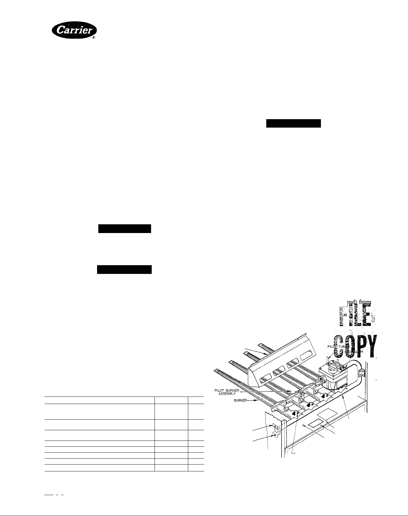
A. Installation of Pilot Orifice
1. Turn off gas and electric supplies to furnace.
2. Remove control access door.
3. Disconnect pilot gas tube from gas valve.
4. Unplug electrode wire from spark generator.
5. Remove pilot assembly from burner and furnace.
6. Using backup wrench, remove gas supply tube from
pilot.
7. Remove and discard propane gas pilot orifice (silver,
5/8-in. long, 0.012-in. diameter orifice, knuHj
gas supply opening of pilot.
SECONDARY
AIR SHIELD
CONTROL
SHELF
UNIT RATING PLATE
CONVERSION
RATING PLATE
MANIFOLD
SUPPORT
BRACKET
RETAINING SCREWS
(2) EACH SIDE
-BURNER
LOCATING PIN
COMPARTMENT
Fig. 1—Gas Controls
MANIFOLD
A80129
Manufacturer reserves the right to discontinue, or change at any time, specifications or designs without notice and without incurring obiigations.
Book] 1 I 4 PC 101 Catalog No. 565-817 Printed in U.S.A. Form 58D,G-2SI Pg 1 11-88 Replaces: 58SSB-4SI
Tab 16a 18a
Page 2
8. Install new natural gas pilot orifice (silver, 1/2-in. long,
0.018-in. orifice diameter).
9. Reinstall pilot gas supply tube bn pilot. When tighten
ing pilot tube, use backup wrench and turn pilot so
that it will be on the same angle as before. Do not rein
stall pilot at this time.
B. Installation of Main Burner Orifices
1. Remove secondary air shield.
2. Remove main burners from manifold.
3. Remove and discard No. 55 (or field-installed per local
application) orifices from manifold.
4. Install No. 45 main burner orifices provided in kit.
Finger-tighten orifices at least one fxill turn so as not to
cross-thread, then tighten with wrench. There are
enough orifices in each kit for the largest furnace. Dis
card extra orifices.
The full input rating with No. 45 main burner natural gas
orifices is approved for altitudes up to 2000 ft. The input
rating for altitudes above 2000 ft must be reduced by 4%
for each 1000 ft above sea level. Consult the current edition
of the National Fuel Gas Code NFPA No. 54/ANSI Z223.1,
Part 8.1 and Appendix F Table F-4, for input adjustment
for high altitude.
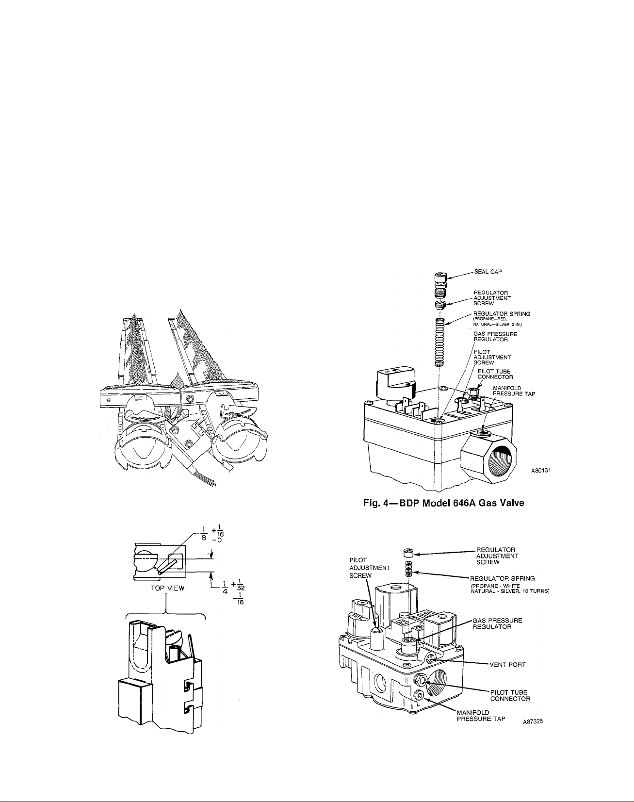
5. Install new burners with N0^ reduction screens on
manifold. See Figs. 2 and 3 for proper orientation of
burners and pilot.
6. Reinstall pilot assembly.
7. Reconnect pilot supply tube to gas valve.
8. Reconnect electrode wire to spark generator.
9. Reinstall secondary air shield.
C. Conversion of Gas Valve and Inlet Gas Pressure
Check
1. Remove regulator seal cap. See Fig. 4 for BDP 646A or
Fig. 5 for White-Rodgers 36E Gas Valve.
2. Remove adjustment screw and propane gas regulator
spring (red for 646A and white for 36E).
3. Install proper natural gas regulator spring (silver) pro
vided in kit, in proper gas valve. See Table 1.
4. Replace regulator adjustment screw. Do not reinstall
regulator seal cap at this time.
5. Remove 1/8-in. pipe plug from inlet pressure tap on gas
valve.
REGULATOR
Fig. 2—Pilot/Burner Relationship
Fig. 3—Position of Pilot Electrode to Pilot
A88463
-REGULATOR
SEAL CAP
Fig. 5—White-Rodgers Model 36E Gas Valve
Page 3

6. Check inlet natural gas pressure.
NOTE: This kit is to be used only when inlet gas pressure is
between 4.5- and 13.6-ins. wc.
a. Attach manometer at inlet pressure tap on gas sup
ply side of furnace gas valve.
A CAUTION
Do not operate furnace more than one minute to check
inlet gas pressure as conversion is not complete at this
time.
b. Set room thermostat “call for heat.”
c. Turn gas supply manual shut-off valve on.
d. Turn furnace gas valve control knob to ON.
e. Turn electrical supply to ON.
f. When main burners have ignited, confirm proper
inlet gas pressure.
g. Turn furnace gas valve control knob to OFF.
h. Turn gas supply manual shut-off valve off.
i. Turn electric supply to furnace to OFF.
j. Remove manometer and replace plug in pressure
tap.
NOTE: Use propane gas-resistant pipe dope. Do not use
Teflon tape.
7. Attach gas control conversion label P/N 310148-302 to
cell panel.
8. Attach conversion rating plate P/N 310168-312 near
existing rating plate. See Fig. 1.
D. Check Furnace Operation and Make Necessary
Adjustments
1. Be sure main gas and electric supplies to furnace are
off.
2. Attach manometer at manifold pressure tap on down
stream side of gas valve.
3. Set room thermostat to “caU for heat.”
A WARNING
Never use a match or other open flame to check for
leaks. Use a soap-and-water solution. A failure to heed
this warning could result in personal injury or death.
4.
Turn gas supply manual shut-off valve on and check
inlet pressure tap plug for leaks.
5.
Turn furnace gas valve control knob to ON and check
all threaded pipe connections for gas leaks.
6.
Turn on electrical supply.
7. When pilot ignites, check pilot gas-supply tube connec
tions for leaks. When main burners ignite, check mani
fold orifices for gas leaks.
8. Determine gas input:
a. Turn off all other gas appliances and pilots.
b. Measure time (in seconds) for gas meter test dial to
complete one revolution.
c. Refer to Table 2 for cubic ft of gas per hour.
d. Multiply cubic ft/hour by Btu cubic ft. Obtain heat
ing value from local gas utihty.
NOTE: Be sure heating value of gas used for calculations is
correct for your altitude. Consult local gas utility for alti
tude adjustment of gas heating value.
High altitude:
The full input rating with No. 45 main burner natural gas
orifices is approved for altitudes up to 2000 ft. The input
rating for altitudes above 2000 ft must be reduced by 4%
for each 1000 ft above sea level. Consult the current edition
of the National Fuel Gas Code NFPA No. 54/ANSI Z223.1,
Part 8.1 and Appendix F Table F-4, for input adjustment
for high altitude.
e. Refer to unit rating plate for gas input rate. The
measured input must be within 2 percent of the rat
ing plate input.
EXAMPLE:
Btuh heating input = Btu/cubic ft times cubic ft/
hour
Heating value of gas = 1070 Btu/cubic ft.
Time for one revolution of 2-cubic-ft dial = 72
seconds
Gas rate = 100 cubic ft/hour (from Table 2)
Btu heating input = 1070x 100 = 107,000 Btuh
9. To adjust input rate:
a. Remove cap that conceals adjustment screw for gas
valve regulator.
b.
Turn adjustment screw either counterclockwise
(out) to decrease input or clockwise (in) to increase
rate. When adjusting input rate, do not set manifold
pressure above 3.8 or below 3.2-ins. wc. Make
any major adjustments by changing main burner
orifices.
Table 2—Gas Rate (Cubic Ft/Hour)
Seconds
for One 1
Revolution cu ft
10 360
11
12
13 277
14 257
15 240
16 225
17
18
19
20
21 171
22
23 157
24
25 144
26
27
28 129
29 124
30 120
31 116
32
33 109
34
35
36 100
37
38 95
39 92
40
41
42
43 84
44
45 80
46 78
47
48
49
SIZE OF TEST DIAL
2 5
cu ft
cu ft
720 1800 50 ' 72 144 360
327
655 1636
300
600 1500
555 1385 53 68 136 340
514 1286 54 67
480 1200 55 65 131 327
450 1125
212
424 1059
200
189 379 947 59 61 122 305
180
164
150
138
133 267 667 74 48 97 243
113 225 563 84 43 86 214
106
103
97
90
88,
86
82
76
75
73 147 367
1000 58 62
400
360
343
327 818
313
300
288
277
257 643 76 47
248 621 78 46 92
240 600 80 45 90 225
232
218 545 86 42 84 209
212 529 88 41 82 205
206 514 90 40
200 500 92 39
195 486 94 38
189 474 96
185 462 98 37
450
180
176 439 102 35 71 178
172 429 104 35
167 419 106 34
164 409 108 33 67 167
160 400 110 33
157 391 112 32 64 161
383 116 31
153
375 120
150
Seconds SIZE OF TEST DIAL
for One
Revolution cu ft cu ft CU ft
51 71
52
56 64
57
900 60 60
857 62 58
783 66 54
750 68 53
720 70 51
692 72 50
581 82 44
64 56
100
69 138 346
63 126
38 75 188
36
30 60 150
1 2 5
141 355
133
129
124
120
116
112
109
106
103
100
95
88
80
78
76
74
72 180
69
68
65
62 155
333
321
316
310
300
290
281
273
265
257
250
237
231
220
200
196
192
184
173
170
164
Page 4

c. Measure adjusted gas input rate using method out
lined in step 8.
d. Replace regulator adjustment screw seal cap.
10. Inspect burner and pilot flame. The main burner flame
should be clear blue, almost transparent. The pilot
flame should be soft blue in color and it must provide
good impingement on the pilot-sensing element. The
flame should extend above the burner carryover port to
provide proper burner ignition. See Figs. 2 and 3. When
the pilot flame requires adjustment:
a. Locate adjustment screw marked PILOT ADJ on
top of gas valve. See Figs. 4 and 5.
b. Remove cap and turn adjustment screw clockwise
to decrease pilot gas flow. Turn screw counter
clockwise to increase pilot gas flow.
c. When proper adjustment is obtained, replace screw
cap.
11. Turn furnace gas valve control knob to OFF.
12. Remove manometer and replace manifold pressure tap
plug.
13. Turn furnace gas valve control knob to ON.
14. With main burners ignited, check pressure tap plugs
for gas leaks.
E. Check Lockout Timer Module (LOD) Operation
1. Turn off electrical supply.
2. With furnace off, remove wire from terminal No. 5 of
gas valve.
3. Set room thermostat to “call for heat.”
4. Turn on electrical supply.
5. Let pilot spark until lockout timer breaks spark genera
tor circuit (approximately 5 minutes).
6. Replace wire on terminal No. 5 of gas valve.
' 7. Electrically reset lockout timer by setting room ther
mostat below room temperature for approximately 30
seconds.
8. Sign and date conversion label P/N 310167-312 pro
vided in kit, and attach to outside of blower compart
ment door.
9. Replace control access door.
10. Reset room thermostat to desired temperature.
During normal operation, if the pilot flame is not proven
within approximately 5 minutes, the lockout timer opens,
deenergiziug the gas valve, and stopping the gas flow to the
pUot. The lockout timer will remain open until it is electri
cally reset.
Manufacturer reserves the right to discontinue, or change at any time, specifications or designs without notice and without incurring obiigations.
B°°k| 1 I 4 PC 101 Catalog No. 565-817 Printed in U.S.A. Form 58D,G-2SI Pg 4 11-88 Replaces: 58SSB-4SI
Tab I6al8a
 Loading...