

Page 1
Gas-Fired Forced-Air Furnace
with Electronic Ignition
INSTALLATION
Before installing the furnace, refer to “Pro
cedures for Gas-Fired Furnaces” (packaged with the
equipment) for information concerning com
bustion, venting, piping, and other standard instal
lation practices. Further reference is made to the
current edition of the American National Standard
Z223.1 National Fuel Gas Code.
Each furnace is shipped from the factory com
pletely assembled with multispeed direct-drive
blower and wired ready for indoor heating installa
tion. All sizes feature a printed-circuit board control
center with easy-to-read low-voltage terminal strip
to ensure proper connections. The control center
also provides easy connections for line-voltage
air cleaners.
CAUTK)?i : Do not iosiaB famace in a corrosive
or contasninated atmospheres Miakesnre that ail
local ordinances for combnstion and oircalating
air supply axe observed.
Table 1 — Clearances (in inches)
SIZES
Sides
Single Wall Vent
Type B — Double Wall Vent
Back
Top of Plenum
Vent Connector
Single Wall
Type B — Double Wall
Front
____
______________
Combustion Air
Service
______
050 & 075
f
0
0
1
6
.
.......
“e
30
_____
100 thru 175
..
1
0
1
6
______
1 _
6
30
The design of the upflow gas-fired furnaces is
A.G.A. certified for installation on combustible
flooring in alcoves, basements, closets, or utility
rooms.
For accessory installation details, i.e., automatic
vent damper, humidifier, electronic air cleaner, etc.,
refer to applicable installation literature.
Electrical Connections
LINE VOLTAGE WIRING
IMPORTANT: Before proceeding with the elec
trical connections, make certain that voltage,
frequency, and phase correspond to that specified
on the unit rating plate. Also, check to be sure that
the service provided by the utility is sufficient to
handle the additional load imposed by this equip
ment. Refer to the unit rating plate for equipment
electrical requirements.
K0'S(4)
Installation comprises the following:
Inspection ....................................................................*
Location, Ventilation and Air
for Combustion........................................................*
Gas Piping....................................................................*
Venting
.........................................................................
Electrical ................................................................... 1
Filter
.............................................................................
Start-Up, Adjustment, and Safety Check
...............
Service....................................................................... 11
*To perform these installation steps, refer to the appropriate
sections of “Procedures for Gas-Fired Furnaces” booklet
packaged with this unit.
© Carrier Corporation 1978
*
7
8
RETURN AIR OPENING
(SIDE) (FIELD CUT EITHER
SIDE) BEND FLANGES UP 90'
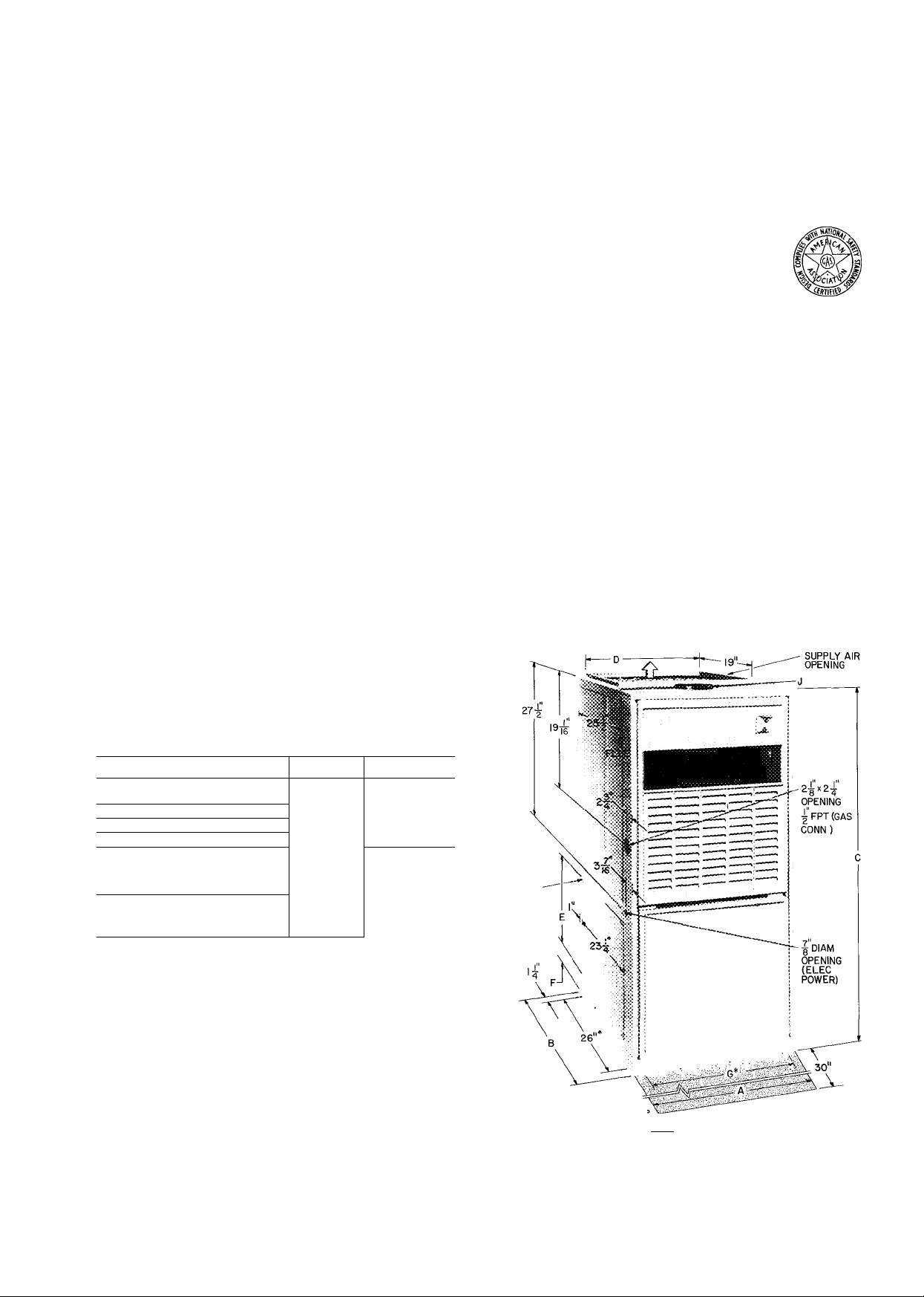
*B0TT0M OPENING ISsjlj SERVICE CLEARANCE C> AIRFLOW
Certified dimension drawings available on request
Fig. 1 — Dimensions
Form 58GS-2SI
Page 2

Table 2 — Dimensions апЭ Physical Data
MODEL NO 58GS
SERIES
DIMENSIONS* (in.)
Width
Depth
Height!
Casing Only
Air Openings
Supply
Side Return (E x 23-1 /4) E
From Opening to Floor F
Bottom Return
Flue (Equiv Round Pipe Dia.) J 4
A
В
c
D
G 11-11/16
FILTERt
Size X 27-3/4 (in.)
RATINGS** (Natural Gas)
Input (1000 Btuh)
Bonnet Cap (1000 Btuh)
Temp Rise!! (F)
Minimum Air for Heating
ESP (in. wg)
Cfm
Max Air Cfm (g) 0 5 in. wg ESP
DD Blower Wheel (nom. size — in.)
HP-Type
BURNERS(No)
APPROX SHIP WT(lb)
ELECTRICAL(S)
Unit Voltage (60-Hz)
Transformer (120-V/24-V)
A/C Blower Relay Rating
@ 120 V (amps)
Motor Full Load Amps
050
100
14-3/16 14-3/16
28-1/2 28-1/2
46-3/16
12-9/16
14-1/2
2-3/4
12-9/16 12-9/16
50
40
40-70 40-70
0 12
673 673
— 815
9x6 9x6
1/IOSh P 1/6Sh P
2
105 105
115 115
20 va
None 138
5
2P0
46-3/16
12-9/16
14-1/2
2-3/4
11-11/16
4
50
40
__
2 2
40 va
6
075
300
14-3/16
28-1/2 28-1/2
46-3/16 46-3/16
12-9/16
14-1/2
2-3/4 2-3/4 2-3/4 2-3/4 2-3/4 2-3/4 2-3/4
11-1 1/16
4
12-9/16 12-9/16 12-9/16
50 75
40 60
35-65 55-85
_
740 793
1170
10x6 9x6
1/3Sh.P 1/10Sh.P
105 122
115
40 va
138
99 5
100
14-3/16
12-9/16
14-1/2
11-11/16 11-1 1/16 11-11/16 15
4 4
0.12
—
3
115
20 va
None
200
14-3/16 14-3/16
28-1/2
46-3/16
12-9/16
14-1/2
75
60 60
55-85 45-75
793 925 925 987 1234
800
9x6 10x6
1/6Sh.P l/3Sh.P 1/6Sh.P
3
122
115 115 115 115 115
40 va 40 va
138
6 9 9 5 5
300
28-1/2 28-1/2 28-1/2 28-1/2
46-3/16
12-9/16 15-7/8 15-7/8 19-3/8
14-1/2 14-1/2
4 5 5 5
12-9/16 15-7/8
75
1150
3
125
138
100
17-1/2
46-3/16
100
80
65-95
0.15
9x7
4
160
20 va
None
100
200 300
17-1/2
46-3/16 46-3/16
14-1/2 14-1/2
15
15-7/8 19-3/8
100
80 80
60-90 45-75
1155 1610
10x7
1/3Sh.P 1/2PSC
4
160 175
40 va 40 va
13 8 13 8
9 9 8 5
21
18-1/2
100
10x8
4
MODEL NO. 58GS
SERIES
DIMENSIONS* (in.)
Width A 21
Depth B 28-1/2
Height!
Casing Only C
Air Openings
Supply D 19-3/8
Side Return (Ex 23-1/4) E 14-1/2
From Opening to Floor F 2-3/4
Bottom Return G 18-1/2 18-1/2 18-1/2
Flue (Equiv Round Pipe Dia ) J
100
46-3/16
5 5
200
21 21
28-1/2
46-3/16
19-3/8 19-3/8
14-1/2 14-1/2
2-3/4
FILTERt
Size X 27-3/4 (in.) 19-3/8
RATINGS** (Natural Gas)
Input (1000 Btuh) 125
Bonnet Cap (1000 Btuh)
Temp Riseft (F)
Minimum Air for Heating
ESP (in wg)
70-100
Cfm
Max Air Cf/n (g) 0.5 in wg ESP
DD Blower Wheel (nom size — in ) 9x8
HP-Type
1/5 Sh P
BURNERS(No)
APPROX SHIP WT(lb) 190
ELECTRICAL(S)
Unit Voltage (60-Hz) 115
Transformer (120-V/24-V) 20 va
A/C Blower Relay Rating
@ 120 V (amps)
Motor Full Load Amps
19-3/8
100
0 20
1089 1157
None
125 125 125
100 100
65-95
—
1230 1550
10x8 10x8
1/3Sh P 1/2 PSC
5
190
115
40 va 40 va 40 va
13 8 13 8
8
5
9 9 8 5
125
300
28-1/2
46-3/16
2-3/4
19-3/8
60-90
1234
190
115
400
24-1/2 24-1/2 24-1/2
28-1/2
46-3/16 46-3/16
22-7/8 22-7/8 22-7/8 22-7/8
14-1/2
2-3/4
5 5
— -
5 5 6 6
22
22-7/8
100
45-75
1543
2110
(2)10x6 10x10 10x10 (2)10x6 (2)10x6
1/2PSC 1/3Sh P 1/2 PSC 1/2 PSC
200
115
13 8 None 138
150
100 200
28-1/2 28-1/2
46-3/16
14-1/2 14-1/2
2-3/4 2-3/4
22 22 22 29
6 6 6 7
22-7/8 22-7/8
150 150 150
120 120 120 140
65-95 65-95 45-75 60-90
0 20
1388 1388 1851 1450
—
205
115 115
20 va 40 va
1600 2110 1980
220
9 5
300 300
24-1/2
28-1/2 28-1/2
46-3/16
14-1/2 14-1/2
2-1/16 2-1/16
22-7/8
— — —
230
115
40 va
13 8
9 5
-
175
31-1/2
46-3/16
29-7/8
29-7/8
1/2 PSC
6 7
40 va
13 8
85 85
175
250
115
ESP — External Static Pressure
DD — Direct Drive
PSC — Permanent Split Capacitor
Sh P — Shaded Pole
*See certified prints for complete
dimensional specifications
tSee Furnace-Coil-Plenum-Adapter
Combinations table in Product Data
Digest Refer to 28 Series literaturefor
plenum dimensions
iDuralast permanent cleanable filters
See manufacturer's recommenda
tions for cleaning
**Ratings shown are for elevations up to
2000 ft above sea level For elevations
above 2000 ft, deduct 4% of input ca
pacity for each 1000 ft above sea level
ttDo not exceed temperature rise speci
fied on furnace nameplate Air tem
perature rise may be calculated using
the following formula:
bonnet capacity
0 24 X specific wt of air x 60 xcfm
bonnet capacity
1 08 X cfm
NOTE: Refer to Application Data litera
ture for complete fan performance
curves
CAOTiON, Air <^.vwy iSOO
i>3ce be or e combioatKi» of
one side ano bottom^ of boisam
on^y for reiurti a>r.
Page 3
CAUTION: Use copper or copper-dad aluiainum conductors only. Use a separate branch
electrical circuit for this furnace. A disconnect
ing means must be located within sight of, and
readily accessible to, the furnace.
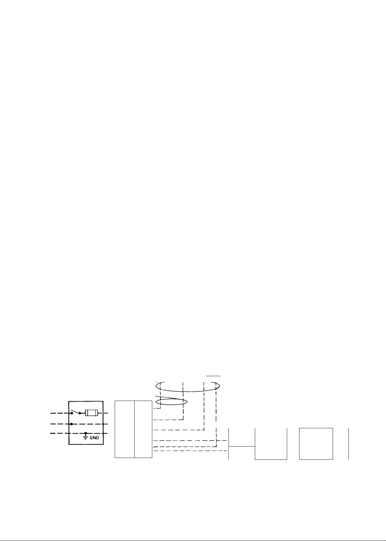
See Fig. 2 for wiring diagram showing the proper
field high- and low-voltage wiring. Make all elec
trical connections in accordance with the National
Electrical Code and any local codes or ordinances
that might apply.
WARNING: The unit cabinet m.ust have an
uninterrupted or unbroken electrical ground to
minimize personal injury if an electrical fanlt
should occur. This may consist of electrical
wire or approved conduit when installed in
accordance with e.Kisting electrical codes.
exposed to cold air infiltration, drafts from win
dows, doors, or other openings leading to the out
side, or exposure to air currents from warm or cold
air registers; or to exposure where the natural circu
lation of the air is cut off — such as behind doors,
above or below mantels, shelves, etc.
The thermostat should not be exposed to heat
from nearby fireplaces, radios, televisions, lamps,
or rays from the sun. Nor should the thermostat be
mounted on a wall containing pipes or warm air
ducts, or a flue or vent that could affect its
operation and prevent it from properly controlling
the room temperature. Any hole in the plaster or
panel thru which the wires pass from the
thermostat should be adequately sealed with suit
able material to prevent drafts from affecting the
thermostat.
LOW-VOLTAGE WIRING — Make field lowvoltage connections at the low-voltage terminal
strip. See Fig. 2.
Set the thermostat heat anticipator at the
settings indicated below. If additional controls are
connected in the thermostat circuit, their amp draw
must be added to this setting. Failure to make the
setting will result in improper operation of the
thermostat.
58GS050 thru 150 sizes with
BDP 646AW gas valve.
Heat/Cool or Heat only models
................
0.55 amp
58GS175 size with Essex 242NS gas valve,
Heat/Cool models.......................................0.65 amp
With addition of automatic vent damper, antici
pator setting should be 0.12 amp.
The room thermostat should be located where it
will be in the natural circulating path of room air.
Avoid locations where the thermostat would be
FOUR WIRE-
NOTES FOR LABEL WIRING DIAGRAMS
1 Screw terminals for field wiring connections
1/4-in quick connect terminals
3 L" If J Heating fan relay contact is normally closed until
r " 115 vac is applied to furnace
4 To change motor speed, move black or red wire to desired speed
setting
5 If any of the original wire as supplied with the appliance must
be replaced, it must be replaced with AWM (105 C) wire or its
equivalent
6 Motor is thermally overload protected
7 Factory speed selection is tor average conditions See installa
tion instructions for optimum speed selection Motor may be 3
or 4 speed
8 Symbols are an electrical representation only
THERMOSTAT
©Cp
TERMINALS
TWO WIRE HEATING ONLY
JL
Jl ©-■
■=r
LOW-VOLTAGE
TERMINAL BLOCK
Field Low-Voltage Wiring
Field High-Voltage Wiring
Factory Low-Voltage Wiring
CONDENSING
I TWO WIRE
&
&-
NOTE: If any of the original wire as supplied, must be replaced,
use same type or equivalent wire
Fig. 2 — Heating and Cooljng Application Wiring Diagram
.q^JZL
-Ijj^
UNIT
— —
-CHMV
——
= GN0
—
SINGLE
PHASE
Page 4
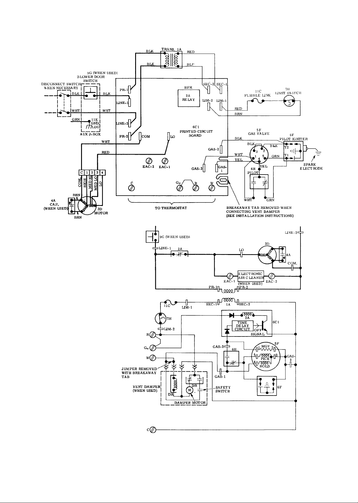
lA-TRANSFORMER 115/24
2 A-RE LAY-HEAT (SPST-NC)
3D-BLOWER MOTOR
4A-RUN CAPACITOR
5F-GAS VALVE
6C1-PRINT ED CIRCUIT BOARD
6F-PILOT IGNITER
6H-SAFETY PILOT (FLAME SENSING)
7H-UMIT SWITCH (SPST-NC)
9G-BLOWER DOOR SWITCH (SPST-N. O. )
IIC-FUSIBLE UNK
HE-GROUND LUG
•FACTORY HIGH-VOLTAGE WIRING
-FACTORY LOW-VOLTAGE WIRING
— — — —FIELD HIGH-VOLTAGE WIRING
Fig. 3 — Label Wiring Diagram; 58GS050-150 Sizes; Heating Only
Page 5
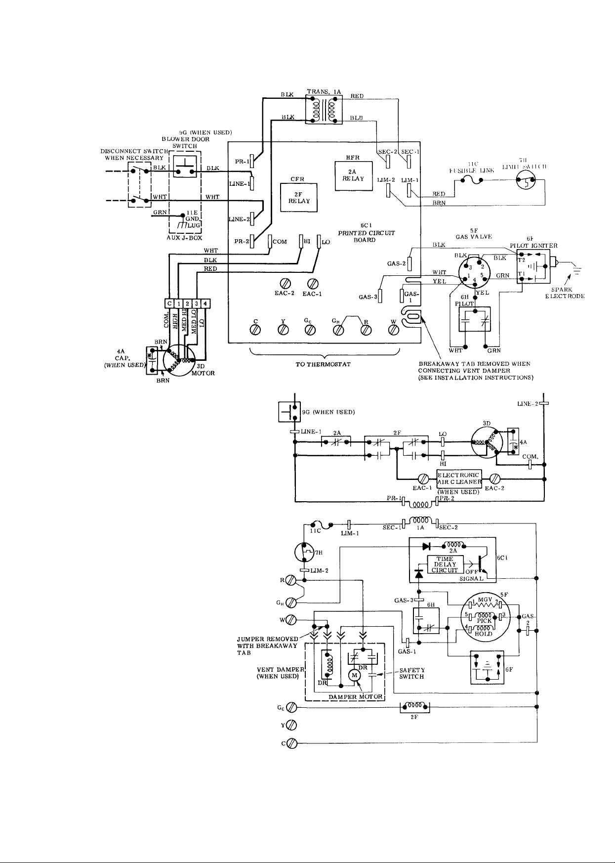
lA-TRANSFORMER lls/24
2A-RELAY - HEAT (SPSP-NC)
2F-RELAY - COOL(DPDT)
3D-BLOWER MOTOR
4A-RUN CAPACITOR
5F-GAS VALVE
6C1-PRINTED CIRCUIT BOARD
6F-PiLOT IGNITER
6H-SAFETY PILOT (FLAME SENSING)
7H-UMIT SWITCH (SPST-NC)
9G-BLOV.ER DOOR SWITCH (SPST-N. O. )
lie FUSIBLE UNK
Uh-GROUND LUG
—
-----------
FACTORY HIGH-VOLTAGE WIRING
--------FACTORY LOW-VOLTAGE WIRING
- — FIE LD HIGH- VOLTAGE WIRING
Fig. 4 — Label Wiring Diagram; 58GS050-150 Si2:es; Heat/Cool
5
Page 6

lA-TRANSFORMER 115/^4
2A-RELAY - HEAT (SPST-NC)
2F-RELAY - COOL. (DPDT)
3D-BLOWER MOTOR
4A-RUN CAPACITOR
5F-GAS valve (TWO CIRCUIT)
6C1-PRINTED CIRCUIT BOARD
6C2- PILOT IGNITER AND FLAME SENSING
7H-UMIT SWITCH (SPST-NC)
9G-BLOWER DOOR SWITCH (SPST-N. O )
nC-FUSIBLE UNK
llE-GROUND LUG
■ FACTORY HIGH-VOLTAGE WIRING
-FACTORY LOW-VOLTAGE WIRING
- — — —FIELD HIGH-VOLTAGE WIRING
Fig. 5 — Label Wiring Diagram; 58GS175 Size; Heat/Cool
Page 7

PRINTED-CIRCUIT CONTROL CENTER —
Each furnace features a printed-circuit control
center to aid the installer and serviceman when
installing and servicing the unit. See Fig. 6. A
low-voltage terminal board is marked for easy con
nection of field wiring and accessories.
CONTROL BOX
w c ^
^ ^ ^
Fig. 6 — Printed Circuit Control Center
Filter
CAUTION: Air deHvety above cfm re
quires that both sides of faraace be used.,
or a combination of one side and bottom,
or bottom only.
FILTER ARRANGEMENT — The filter is factory
installed in the bottom of the furnace. This is for
bottom inlet application. See Fig. 7.
NOTE: Remove and discard bottom closure panel
when bottom inlet is used.
For side inlet application, see Fig. 1 for the
opening size. Remove the filter from the bottom of
furnace and relocate at the side by performing the
following steps:
1. Remove screws from filter retainer clips at both
sides of furnaee.
2. Remove retainer spring and position both clips at
inlet side of furnace.
3. Remove filter from bottom and position on inlet
side of furnace.
4. Place retainer spring over filter, making certain
to position front of retainer spring behind flange
of the casing side.
5. Install the retainer spring in the holes provided —
one in the bracket at bottom rear and the other
in the hole in blower deck. See Fig. 8.
Fig. 7 — Filter Installed for Bottom Inlet
Fig. 8 — Filter Installed for Side Inlet
Page 8

BOTTOM CLOSURE PANEL — When the side
inlet is used, the bottom opening must be properly
sealed by installing a bottom closure panel shipped
under the filter in each furnace. To install the
bottom closure panel, perform the following steps:
After filter has been installed for side return, re
1.
move bottom closure panel from furnace.
With furnace either tilted or raised, install panel
in opening on bottom of furnace, making certain
that locating tabs rest securely against sides
of cabinet. See Fig. 9.
WARNING: Never operate unit without a iiiter
or with filler acce.ss door removed-
START-UP. ADJUSTMENT AND
SAFETY CHECK
Sequence of Operation
HEATING — Sizes 050 thru 150 (BDP 646AW gas
valve)
TIME (sec)* ACTION
Thermostat calls for heat. The control circuit be
0
tween R and W is closed: power from transformer
simultaneously opens solenoid of pilot gas valve
(inside main gas valve) and energizes spark
igniter
PiTot^as ignites
TTlof coritacTslnbffnaTly closed) open.'Spark
igniter ceases to spark
35
“”45'’
11b
20
75
‘Times are approximate: variance ±20%
Pilot contacts (normally open) close, energizing
heat motor in main gas valve and solid-state
timing circuit in printed circuit control centejr^
Heat motor opens main gas valve; main Burners
ignite from pilot flame
SoHd^itife tirning'cnxuiUswitches iti contacts
and blower motor starts
Thermostat is satisfied. Circuit between R and W
is broken; automatic gas valve is de-energized,
closing solenoid valve Solid-state timing circuit
is de-energized
T^in gas "valvelmd pilot valve close, extinguishing
flame
Piiot safety contacts open.
PIloTcontacts cioseTready for new cycle Solid-
state timing circuit switches its contacts, stopping
blower motor
______
eorroM
aosu!^ PANEL
Fig. 9 — Installing Bottom Closure Panel
LOCATING TASS
HEATING — Size 175 (Essex 242 gas valve)
TIME (sec)*
0
75
75
‘Times are approximate, variance ±20%
Thermostat calls for heat, power from transformer
simultaneously opens solenoid of pilot gas valve
(inside main gas valve) and energizes spark
igniter Solid-state timing circuit is energized
Pilot gas ignites
Once pilot flame is proven electrically, igniter
ceases to spark, main gas valve opens and mam
burners ignite from pilot flame
Solid-state timing circuit switches its confacfs
and blower motor starts
Thermostat is satisfied Pilot and main gas valves
are de-energized Solid-state timing circuit is
de-energized _ _
Pilot and main burners are extingmsh^_
1
Solid-state timing circuit switches its contacts,
stopping blower motor
ACTION
____________
LIMIT SWITCH — If the furnace overheats for
any reason, the limit switch will open, breaking the
circuit to automatic gas valve, so the gas valve
closes immediately. Without low-voltage current
applied to heat relay, its normally closed contacts
energize blower motor.
Page 9

#
m
OVERHEAT FUSE LINK — The furnace is
equipped with a fusible element to protect against
overtemperature conditions in the vestibule that can
result from inadequate combustion air supply.
WARNÌNG: 0o rtot bjpass tììc fusible element
ob&îÏÊCtéd betwëèù tbe ÌKmti;|ÌIIÌ
lì ii;i©pe}3Sÿi)Sîaife^:
4ÏÎÉ:
m
the combiìi!tìou: air soppìy:..
etemeut vwth au idejRîicaîpari;
HYïOLFm.
REGULATOR
ADJUSTMENT
Fig. 10 - BDP 646AW Gas Valve
PILOT ADJUSTING SCREW CAP
MANUAL SHUTOFF VALVE
AND PILOT COCK
LOW VOLTAGE
CONNECTIONS
REGULATOR ADJUSTING
COVER (ADJUST "Hi"
SIDE SCREW)
PILOT GAS LINE
CONNECTION
MAIN GAS CONNECTION
PRESSURE TAP
Fig. 11 — Essex 242 Gas Valve
PILOT
ADJUSTMENT
PILOT
TUBE
CONNECTION
COOLING — When the thermostat calls for cool
ing, power from the transformer energizes the
blower relay coil, closing its normally open contacts,
and energizing the blower motor on its cooling
speed. It continues to operate until the thermostat
is satisfied.
When the thermostat is satisfied, the circuit to
terminal (G) is broken, de-energizing the blower
relay coil which, in turn, opens its contacts, stopping
the blower motor.
AUTOMATIC GAS CONTROL VALVE The
automatic gas valve controls the flow of gas to both
pilot and main burners. All models have the manual
valve built into the automatic valve body. The
manual valve has only 2 positions: OFF and ON. It
does not have an intermediate position for pilot gas
flow only.
To shut off the gas manually, turn knob from ON
to OFF position. When in OFF position, the main
burners and the pilot flame are extinguished.
Starting Procedure — Check to be sure that all
connections have been properly made, then pro
ceed as follows:
Use the procedure outlined on the Lighting In
struction Plate attached to the furnace. See Se
quence of Operation and perform the following
additional steps:
1. If supply line was not purged before connecting
furnace, it will be full of air. It is recommended
that pilot supply line be disconnected at pilot
shutoff valve or main gas valve, and supply line
be allowed to purge until odor of gas is detected.
Never purge gas lines into combustion chamber.
Immediately upon detection of gas odor, re
connect pilot supply tube. Allow 5 minutes to
elapse before lighting furnace.
2. Pilot flame should be soft blue in color.
For natural gas controls, flame should be of
sufficient length to provide good impingement
on element of pilot. Flame should extend upward
between carryover ports of 2 adjacent burners.
3. Pilot adjusting screw is located on main gas
valve, or pilot shutoff valve.
a. Remove capscrew; turn pilot gas full on and
adjust adjusting screw until desired appear
ance is obtained.
b. Replace capscrew.
Gas Input — Determine the gas input as follows:
1. Natural Gas
a. Turn off all other gas appliances and pilots.
b. Measure time (in seconds) for gas meter test
dial to complete one revolution.
c. Divide 3600 by time noted and multiply result
by number of cu ft per revolution of test dial
(read off meter test dial).
________3600________ ^
seconds per revolution
cu ft per _ cu ft
revolution per hr
Page 10

d. Multiply cu ft per hour times heating value of
gas (Btu/cu ft). Obtain heating value of gas
from local utility.
X heat value of gas
= gas input, Btuh
Example:
Time for one revolution of 2 eu ft dial = 72
seconds.
Heat value of gas = 1070 Btu/cu ft
3600
X 2 = 100 cu ft/hr
72
100 X 1070 = 107,000 Btuh
e. To adjust input rate, remove cap that con
ceals regulator adjustment. Turn adjusting
screw counterclockwise (out) to decrease
input. When adjusting, DO NOT change
manifold pressure more than 0.3 in. wg. Any
major adjustment should be made by chang
ing orifices.
2. High Altitude
Ratings are approved for altitudes to 2000 ft
for all gases. Ratings for altitudes over 2000 ft
are 4% less for each 1000 ft above sea level.
3. Adjust air temperature rise by adjusting blower
speed. Increase blower speed to reduce tempera
ture rise. Decrease blower speed to increase
temperature rise.
Adjustment of Blower Speed
WARN!N<?: Disconnect ekctrical power before changing speed, tap.
To change motor speed, remove the electric lead
from left side of Molex speed selector (see Fig. 7)
and relocate it on the desired terminal on the plug-in
terminal block/ speed selector located on the blower.
The white lead remains in the “C” (common) ter
minal at all times. The black lead (on heat/cool
models) is used to select the proper speed for
cooling mode and the red lead is used to select the
speed for heating mode.
CAOTTON: "Whien adjasisn^ ihe blower speed,
make cefiain that the temperature rise across
the heat exchanger does not exceed that speci
fied on the rating plate.
Table 3 — Speed Selector
Adjust Main Burner Flame — The main burner
flame should be clear blue, almost transparent, with
a well-defined inner cone. If there is too much pri
mary air, the flame will be well defined, but with a
tendency to float or lift off the burner ports.
1. Allow unit to operate 5 minutes.
2. When burners are equipped with primary air
adjustment, adjust each burner by closing air ad
justment device until slight yellow tip appears on
flame; then open, just enough to clear yellow
from flame.
Temperature Rise — Determine the air tem
perature rise as follows:
1. Place duct thermometers in return and supply
ducts as near furnace as possible. Be sure
thermometers do not “see” heat element so that
radiant heat will not affeet thermometer read
ings. This is particularly important with straightrun ducts.
2. When thermometers stabilize, subtract return air
temperature from supply air temperature to
determine air temperature rise.
SPEED
Common C
Hi
Med-Hi
Med-Lo 3
Lo 4
TAP NO
......................1......................
2
.......................
NOTE: Series 100 (heating only) and 150-200 have
3-speed motor.
Limit Control Safety Check — This control
shuts off the gas and energizes the blower
motor if the furnaee becomes overheated.
The recommended method of checking the
limit control is to gradually block off the return
air after the furnace has been operating for a
period of at least 5 minutes. As soon as the
limit has proven safe, the return air opening
should be unblocked to permit normal air circu
lation. By using this method to check the limit
control, it can be established that the limit is
functioning properly and will “fail-safe” if there
is a motor failure.
10
Page 11

SERVICE
CAUTION: Tixe abüîty to properly perform
maintenance on this equipment requires certain
mechanical skills and tools. If yott are at all
uncertain, contact your Carrier deaier lor
qualified maintenance and .service..
proper procedure for checking and cleaning the
filter.
Blower Motor and Wheel — For long life,
economy, and high efficiency, clean accumulated
dirt and grease from blower wheel and motor
annually.
Regular maintenance, exercised with care, results
in more efficient operating life of your furnace.
Periodic filter changes, along with inspection
and cleaning of the heat exchanger, inspection
and lubrication of blower motor and wheel, and
checking for tight electrical connections and proper
operation of controls each season, help insure
reliable service.
WARNîNC: Tura oft ali gas and electrical
power to furnace before performing my main
tenance or service on unit. Failure to take this
precaution may result in personal injury' dtte to
electrical shock or uncontrolled gas leakage.
Air Filter
SAFETY INSTRUCTIONS; in order to
acquaint the user of the furnace with proper
procedure for checking and cleaning the filter,
the installer should instruct the user to perform
the steps described below.
Remember to disconnect electrical power before
removing access panels. To clean or replace air
filter, proceed as follows;
1. Remove blower access door.
2. Release filter retainer spring from behind flange
of furnace casing.
3. Slide filter out.
4. Clean filter with tap water.
5. Rinse and let dry. No oiling or coating of filter
is required.
6. Place filter in furnace with cross-sectional
binding up or facing blower.
CAUTION: As with any mechanical equipment,
personal injury can result from sharp metal
edges, etc.; therefore, be careful when removing
parts.
Lubricate motor every 5 years if motor is used on
intermittent operation (thermostat FAN switch in
AUTO, position), or every 2 years if motor is in con
tinuous operation (thermostat FAN switch in ON
position).
Remember to disconnect electrical supply before
removing access panels.
Clean and lubricate as follows:
1. Remove access panels.
2. Remove electrical leads from left side of Molex
speed selector. See Fig. 7. Note location of
wires for reassembly.
3. Remove screws holding blower assembly
against blower deck and slide blower assembly
out of furnace.
4. Squeeze side tabs of Molex speed selector and
pull it from blower housing.
5. Loosen a screw in strap holding motor capacitor
to blower housing and slide capacitor from
under strap.
6. Mark blower wheel, motor, and motor
support in relation to blower housing before dis
assembly, to insure proper reassembly.
7. Loosen setscrew holding blower wheel onto
motor shaft.
NOTE: Eurnaces with dual blowers, remove right
blower and wheel first as shown in Fig. 12.
CAUTION: Personal injury or property
damage may result if furnace is operated with
the blower cotnpartmeni door removed. A lack
of adequate combustion air may cause the main
burner flame to be drawn out of the furnace
unless blower compartment door is secured.
After inspecting or replacing the filter, be
sure that blower compartment door is securelyfastened in place.
NOTE: If external filter rack is used in place of
internal filter mounting, inform the user of the
Fig. 12 — Dual Blower with Right-Hand
Housing and Wheel Removed
Page 12

8. Remove bolts holding motor mount to blower
housing and slide motor and mount out of
housing. Some motors have a ground wire
attached to blower housing: disconnect it also.
9. Lubricate motor.
a. Remove dust caps or plugs from oil ports
located at each end of motor.
b. Use a good grade of SAE 20 nondetergent
motor oil and put 16 to 25 drops in each oil
port.
c. Allow time for total quantity of oil to be
absorbed by each bearing.
d. After oiling motor, be sure to wipe excess
oil from motor housing.
e. Replace dust caps or plugs on oil ports.
10. Remove blower wheel from housing.
a. Mark blower wheel orientation and cutoff
location to insure proper reassembly.
b. Remove screws holding cutoff plate and
remove cutoff plate from housing.
c. Lift blower wheel from housing thru
opening.
11. Clean blower wheel and motor by using vacuum
with soft brush attachment. Care must be exer
cised not to disturb balance weights (clips) on
blower wheel vanes. Also, do not drop or bend
wheel, as balance will be affected.
12. Reassemble blower by reversing procedures 10a
thru c. Be sure wheel is positioned for proper
rotation.
13. Reassemble motor and blower by reversing
procedures 4 thru 8. If motor has ground wire,
be sure it is connected as before.
14. Reinstall blower assembly in furnace.
15. Connect electrical leads to Molex speed
selector. Please note that connections are
polarized for assembly — do not force.
16. Turn on electrical power and check for proper
rotation and speed changes between heating
and cooling.
FLUE baffles
Fig. 13 — Removing Baffles
8. Replace flue baffles and chokes. Be sure all
screws are in place and tight.
9. Replace draft diverter and vent connector. Be
sure screws are replaced and tight.
10. Replace secondary air baffle and burners.
11. Turn on gas and electricity. Check for gas leaks.
WARNING: Never use a match or other open
flame to check for gas leaks. Use a soap-andwater solution.
Pilot — Pilot should be checked and cleaned if
necessary at the beginning of each heating season.
Pilot flame should be high enough for proper
impingement of the flame sensing probe. Remove
accumulation of soot, dirt, and carbon from probe
and electrode if necessary.
Cleaning Heat Exchanger — If it becomes neces
sary to clean the heat exchanger because of carbon
deposits, soot, etc., proceed as follows:
1. Turn off gas and electrical supply.
2. Remove access panels.
3. Remove vent connector and draft diverter.
Screws are located inside draft diverter opening.
Remove chokes.
4.
Remove flue baffles from flue outlets of heat
5.
exchanger. See Fig. 13.
Remove secondary air baffle and burners. To
6.
remove pilot burner, disconnect pilot supply
tube at gas valve.
Clean flue ways with brush and/or vacuum.
7.
Check heat exchanger for leaks and cracks.
Replace if necessary.
Electrical Controls and Wiring
NOTE: There may be more than one electrical
supply to unit.
With power disconnected to unit, check all
electrical connections for tightness. Tighten all
screws on electrical connections. If any smoky or
burned connections are noticed, disassemble the
connection, clean all parts and stripped wire, and
reassemble properly and securely. Electrical con
trols are difficult to check without proper instru
mentation. Therefore, reconnect electrical power to
unit and observe unit thru one complete operating
cycle. If there are any discrepancies in the operating
cycle, contact your Dealer and request service.
12
Page 13

^ OF PILOT
«.OFPJLOr
(ESSEX 242 GAS VALVE)
Fig. 14 — Position of Electrode to Pilot Shield
Fig. 15 — Proper Location of Carry-Over in
Relation to Top of Burner
13
Page 14

Table 4 — Trouble Analysis Chart
WARNING: Turn off gas and power supply to ur»it before servicing.
(Unless specific test requires gas and electrical supplies.}
Blower operates continuously
Inadequate heating
Aldehyde odors, (CO),
sooting flame — floating flame
CAUSE
No spark at electrode
Spark shorting out to main burner
No gas at pilot burner
Noll 5-volt power to furnace
No 24-volt power to control circuit
Miswired or loose connections
No gas at main burners
Flame probe or connecting lead is
shorted or open
Dirty pilot — yellow flame
Thermostat fan switch in ON position
Fusible link blown
Dirty filter causing limit operation
Defective heat relay
Furnace undersized for application
Gas input to furnace too low
Limit switch cycles main burners
Incomplete combustion — poor
flame characteristics
REMEDY
Check air gap between electrode tip and pilot burner It should
be 1/8 +1/16 on BDP gas valve; 3/32 +0 025 onEssexgas
-0 -0.005
valve Readjust if necessary
Check moisture or dirt accumulation on electrode ceramic —
clean ceramic with cloth
Cracked ceramic — replace pilot electrode assembly
Check for loose or broken wiring at and between electronic con
trol box and electrode Replace wire as necessary
Check fuse or circuit breaker for 11 5-volt supply to furnace.
Check 24-volt input to electronic control box If you read 24 volts
and above steps have been completed, replace electronic
control box assembly
Realign electrode tip away from main burner but maintain
spark gap to pilot burner as jtote^above ___
Check to see if pilot valve is opening Look for loose or broken
wiring connections If no deficiency is found, replace valve
assembly
Connect to power supply Check fuse, wiring, or circuit breal^r
Check transformer — replace
Check_all wiring and wirenut connections.
Check to see if main valve is opening Look for loose or broken
wiring connections If no deficiency is found, replace valve
assembly _
Correct electrical shorting or open circuit
Clean pilot orifice
Move thermostat fan switch to AUTO position
Correct combustion air and venting practice — replace fuse
link with identical part
Clean dirty air filter — reinstall
Replace printed circuit board
Replace with proper size furnace _
Check gas pressure at manifold Clock gas meter for input If
too low, increase manifold pressure, or replace with correct
orifices
pFF setting of fan control set too high — reset. ____ _
Dirty air filters — clean and reinstall.
____
_ _
_____________________
_______________________
_
___ ______
slower speed too low — use faster speed tap
Registers closed, restricted ductwork — open or remove
restriction
Check heat anticipator setting on thermostat — readjust
Air shutter on burners — closed — adjust to soft blue flajjip^
Check all screws around flue outlets and burner compartment
— tighten
LACK OF COMBUSTION AIR — see instructions.
Cracked heat exchanger — replace.
Overfired furnace — reduce input, or change orifices
Check vent for restriction — clean as required
__
14
Page 15

For replacement items use Carrier Specified Parts.
Manufacturer reserves the right to discontinue, or change at any time, specifications or designs without noticeand without incurring obligations.
Book 1
Tab
4
6a
8a
Form 58GS-2SI Supersedes 58GS-1 SI Printed in U S.A 8-78
PC 101
Catalog No 535-880
 Loading...