

Page 1
HEATING & COOLING
58EFA
Gas-Fired Horizontal
Induced-Combustion Furnaces
Service and Maintenance instructions
For Sizes 050-125, Series 110
NOTE: Read the entire instruction manual before starting the
installation.
SAFETY CONSIDERATIONS
Installing and servicing heating equipment can be hazardous due to
gas and electrical components. Only trained and qualified person
nel should install, repair, or service heating equipment.
Untrained personnel can perform basic maintenance functions
such as cleaning and replacing air filters. All other operations must
be performed by trained service personnel. When working on
heating equipment, observe precautions in the literature, tags, and
labels attached to or shipped with the unit and other safety
precautions that may apply.
Follow all safety codes, including NFPA 54/ANSI Z223.1-1988,
National Fuel Gas Code. Wear safety glasses and work gloves.
Have fire extinguisher available during start-up and adjustment
procedures and service call.
Recognize safety information. This is the safety-alert sy
When you see this symbol on the unit and in instructions or
manuals, be alert to the potential for personal injury.
Understand the signal word—DANGER, WARNING, or CAU
TION. These words are used with the safety-alert symbol. DANGfeR'idehtifies the most serious hazards which will result in severe
personal injury or death. WARNING signifies hazards that could
result in personal injury or death. CAUTION is used to identify
unsafe practices, which would result in minor personal injury or
product and property damage.
A WARNING
Never store anything on, near, or in contact with, the furnace,
such as:
1. Spray or aerosol cans, rags, brooms, dust mops, vacuum
cleaners, or other cleaning tools.
2. Soap powders, bleaches, waxes or other cleaning com
pounds, plastic or plastic containers, gasoline, kerosene,
cigarette lighter fluid, dry cleaning fluids, or other volatile
fluids.
3. Paint thinners and other painting compounds, paper bags or
other paper products.
Failure to follow this warning can cause corrosion of the heat
exchanger, fire, personal injury, or death.
A WARNING
The ability to properly perform maintenance on this equip
ment requires certain expertise, mechanical skills, tools, and
equipment. If you do not possess these, do not attempt to
perform any maintenance on this equipment other than those
procedures recommended in the User’s Manual. FAILURE
TO FOLLOW THIS WARNING COULD RESULT IN
POSSIBLE DAMAGE TO THIS EQUIPMENT, SERIOUS
PERSONAL INJURY, OR DEATH.
CARE AND MAINTENANCE
For continuing high performance and to minimize possible equip
ment failure, it is essential that maintenance be performed annually
on this equipment. Consult your local dealer for maintenance and
the availability of a maintenance contract.
Book 1 4
Tab 6a 8a
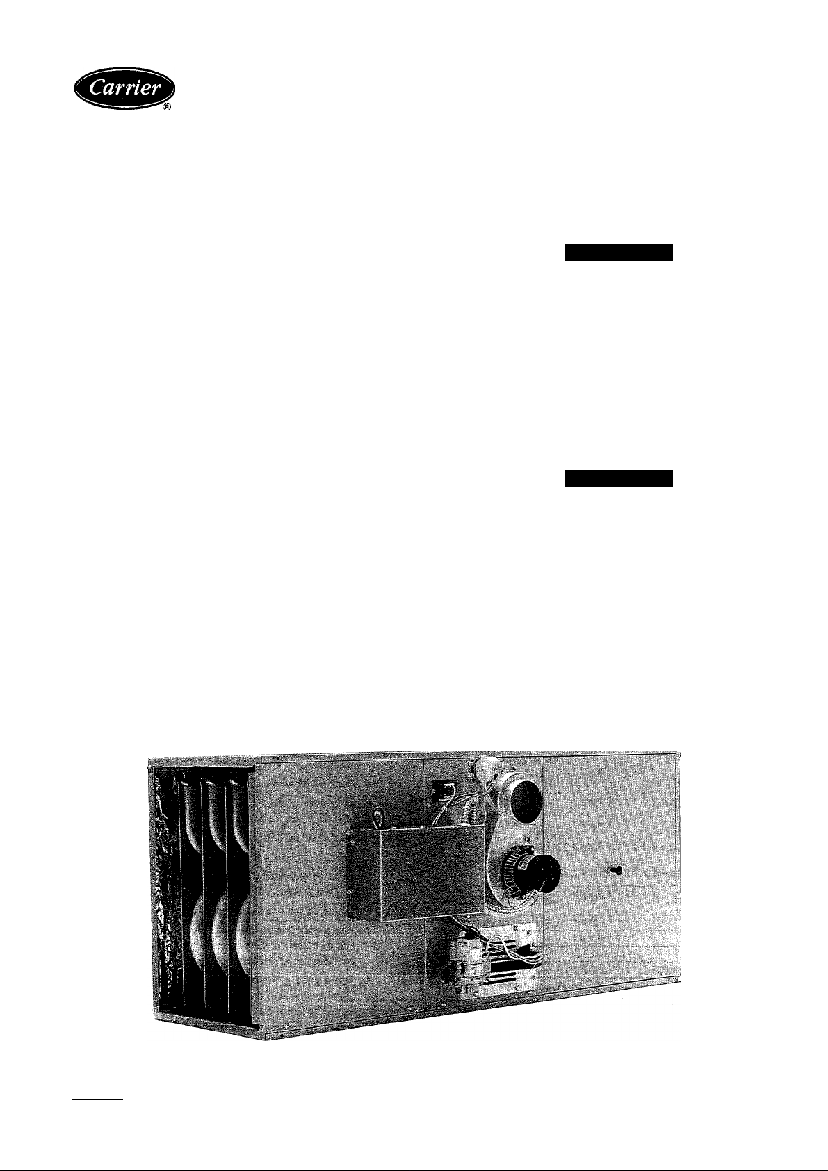
Fig. 1—Model 58EFA Horizontal Furnace
Manufacturer reserves the right to discontinue, or change at any time, specifications or designs without notice and without incurring obiigations.
PC 101
Catalog No. 565-839 Printed in U.S.A.
Form 58EFA-2SM
Pg1
8-92
Replaces: 58EFA-1SM
A91314
Page 2
A WARNING
Turn OFF the gas and electrical supplies to the unit before
performing any maintenance or service. Follow the operating
instructions on the label attached to the furnace. Failure to
follow this warning could result in personal injury.
The minimum maintenance that should be performed on this
equipment is as follows:
1. Check and clean or replace air filter each month, or as
required. (See Step 1.)
2. Check blower motor and wheel for cleanliness and lubrication
each heating and cooling season. Clean and lubricate as
necessary. (See Step 2.)
3. Check electrical connections for tightness and controls for
proper operation each heating season. Service as necessary.
4. Check for blockages of vent pipe.
A CAUTION
As with any mechanical equipment, personal injury could
result from sharp metal edges, etc. Be careful when removing
parts, panels, or components.
Step 1—Air Filter Cleaning and Replacement
The air filter arrangement may vary depending on the application.
Each furnace may be supplied with a permanent, washable filter
and wire filter retainer option. If so, the filter is normally located
in the return-air plenum opening before the blower. (See Fig. 2.)
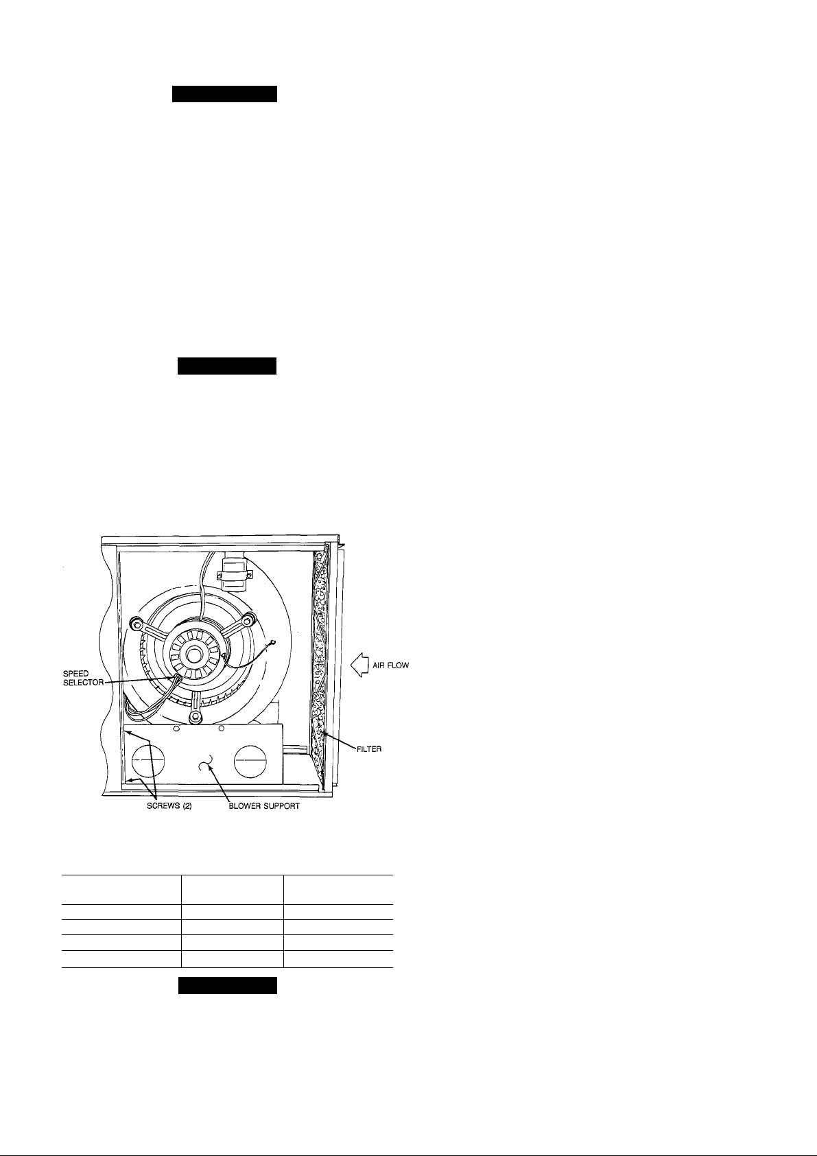
Fig. 2—Blower Compartment
A91175
Table 1—Horizontal Furnace Filters
FURNACE SIZE
(INPUT BTUH)
50,000
75,000 (1) 13x23x1 Cleanable
100,000 (1) 16x23x1 Cleanable
125,000 (1) 20x23x1
FILTER SIZE
(IN.)
(1) 13x23x1 Cleanable
FILTER TYPE
Cleanable
A CAUTION
Never operate unit without a filter or with filter access door
removed. Failure to follow this warning could result in a fire
or personal injury.
To clean or replace the filters, proceed as follows;
1. Turn OFF electrical supply to unit.
2. Remove blower access door located at inlet (return air) end of
furnace; 4 screws must be removed.
3. Bend wire filter retainer until it clears furnace flange and
swing it toward the blower.
4. Remove filter from furnace. If filter is tom, replace it.
5. Furnaces may be equipped with permanent, washable filters.
Clean these filters by spraying cold tap water through filter in
opposite direction of airflow. A mild liquid detergent may be
used if necessary.
6. Rinse filters and let dry. Oiling or coating of filters is not
recommended or required for factory-supplied filters.
7. Reinstall filters with cross-mesh binding facing blower.
8. Replace blower access door and reinstall 4 screws.
9. Turn ON electrical supply to furnace.
Step 2—Blower Motor and Wheel Maintenance
For long life, economy, and high efficiency; clean accumulated
dirt and grease from blower wheel and motor annually.
The following items should be performed by a qualified service
technician:
Some motors have prelubricated, sealed bearings and require no
lubrication. These motors can be identified by the absence of oil
ports on each end of the motor. For motors with oil ports, lubricate
as follows:
Lubricate motor every 5 years if motor is used for intermittent
operation (thermostat FAN switch in AUTO position), or every 2
years if motor is in continuous operation (thermostat FAN switch
in ON position).
Clean and lubricate as follows:
1. Turn OFF electrical supply to unit.
2. Remove blower access door; 4 screws must be removed.
3. Remove blower assembly as follows:
a. Remove 4 screws securing front blower support bracket
and remove bracket. (See Fig. 2.)
b. Using a 3/8-in. ratchet with a 3-in. extension, reach through
4-in. diameter holes in rear blower support bracket and
remove 2 screws securing bracket to blower shelf. (See Fig.
2.)
c. Disconnect motor leads from motor speed selector. (See
Fig. 2.)
d. Remove blower assembly from unit.
4. Mark blower wheel location on shaft before disassembly to
insure proper reassembly.
5. Loosen setscrew holding blower wheel on motor shaft.
6. Disconnect ground wire from blower housing.
7. Remove bolts holding motor mount to blower housing and
slide motor and mount out of housing.
8. Lubricate motor (when oil ports are provided).
a. Remove dust caps or plugs from oil ports located at each
end of motor. If motor does not have these caps or plugs,
bearings are sealed and need no further lubrication.
b. Use a good grade of SAE 20 nondetergent motor oil and
add 1 teaspoon (5 cc, 3/16 oz, or 16 to 25 drops) in each oil
port. The use of other types or grades of oil will damage the
motor. Excessive oiling can cause premature bearing fail
ures.
c. Allow time for total quantity of oU to be absorbed by each
bearing.
WA
Page 3

d. After oiling motor, wipe excess oil from motor housing.
e. Replace dust caps or plugs on oil ports.
9. Remove blower wheel from housing.
a. Mark blower wheel orientation and cutoff plate location to
insure proper reassembly.
b. Remove screws securing cutoff plate and remove cutoff
plate from housing.
c. Remove blower wheel from housing.
10. Clean blower wheel and motor using a vacuum with soft brush
attachment. Be careful not to disturb balance weights (clips)
on blower wheel vanes. Do not drop or bend wheel as balance
will be affected.
11. Reassemble blower by reversing items 9.a. through 9.c.
Ensure wheel is positioned for proper rotation.
12. Reassemble motor and blower by reversing items 3 through 7.
Reconnect motor ground wire.
A CAUTION
Ensure the motor is properly positioned in the blower
housing. The motor oil ports must be at a minimum of 30°
above the horizontal centerline of the motor after the blower
assembly has been reinstalled in the furnace.
13. Reinstall blower assembly in furnace.
14. Connect electrical leads to motor speed selector; do not force
leads.
15. Turn ON electrical supply and check for proper rotation and
speed changes between heating and cooling.
Step 3—Cleaning Heat Exchangers and Burners
The following items should be performed by a qualified service
technician:
If it becomes necessary to clean the heat exchanger because of
carbon deposits, soot, etc., proceed as follows:
NOTE: Deposits of soot and carbon indicate a problem exists that
needs to be corrected. Action must be taken to correct the problem.
1. Turn OFF gas and electrical supplies to furnace.
2. Using a backup wrench, disconnect gas supply at ground joint
union. Remove gas pipe from gas valve.
3. Disconnect electrical wiring from gas valve.
4. Remove bumer/manifold assembly as follows:
a. Remove air inlet plate/burner removal cover.
b. Remove manifold retention plate from front of unit.
c. Loosen screws in manifold retention plate at rear of unit.
d. Disconnect wiring to ignition electrode/flame sensor.
e. Remove bumer/manifold assembly from unit.
5. Place burner/manifold assembly on flat work surface and
clean burner ports. Use a soft brash to loosen dirt, then
vacuum.
6. Using a small rubber mallet, gently tap each burner opening to
loosen any debris in heat exchanger cells.
7. Brush each heat exchanger cell using a nylon heat exchanger
brush with a long, flexible handle.
8. Vacuum each heat exchanger cell and burner box with a
crevice tool attachment.
9. Check position and alignment of pilot assembly to burners and
ignition electrode to ignition hood. (See Fig. 3.)
10. Reinstall burner/manifold assembly and front manifold reten
tion plate.
11. Tighten screws securing rear manifold retention plate.
12. Reconnect wiring to ignition electrode/flame sensor.
13. Reinstall air inlet plate/bumer removal cover.
14. Using wiring diagram (Fig. 7.) reconnect wiring to gas valve.
15. Apply joint compound (pipe dope) sparingly to male ends of
gas pipe and reinstall gas pipe in gas valve.
NOTE: Joint compound must be resistant to the action of propane
gas.
16. Reconnect ground joint union.
17. Turn ON gas and electrical supplies to furnace.
18. Check gas supply line for leaks.
A WARNING
Never use matches, candles, flame, or other sources of
ignition to check for gas leakage. Use a soap-and-water
solution. Failure to follow this warning could result in a fire,
personal injury, or death.
19. Check furnace operation through 2 complete operating cycles.
Look through vent openings in burner enclosure to check
burners. Main burner flames should be clear blue, almost
transparent. Pilot flame should be soft blue in color, well
defined, and must provide good impingement of the ignition
electrode/flame sensor. Pilot flame should extend above
burner carryover port to provide proper burner ignition. (See
Fig. 3, 4, and 5.)
Fig. 4—Position of Piiot to Ignition Electrode/FIame
Sensor
Page 4

PILOT FLAME BURNER FLAME
Step 4—Pilot Assembly
Check the pilot assembly and clean if necessary at the beginning of
each heating season. The pilot flame should be high enough for
proper impingement of the ignition electrode/flame sensor and to
light the burners. Remove any accumulation of soot and carbon
from the flame sensor. Check spark ignition electrode gap. (See
Fig. 3, 4 and 5.)
Step 5—Electrical Controls and Wiring
NOTE: There may be more than 1 electrical supply to the unit.
Refer to Fig. 6 for field application wiring and Fig. 7 for unit
wiring. With power disconnected to the unit, check all electrical
connections for tightness. Tighten all screws on electrical connec
tions. If any smokey or burned connections are found, disassemble
the connection, clean all parts, strip wire, and reassemble properly
and securely.
Reconnect electrical power to the unit and observe unit through 1
complete operating cycle. Electrical controls are difficult to check
without proper instrumentation. A good voltmeter is needed to
check for correct operation of controls and wiring.
If the furnace fails to operate, check the following items before
calling for service:
1. Is the thermostat set correctly to "call for heat?"
2. Are the electrical and gas supplies ON?
3. Are the filters clean?
Refer to the Trouble Analysis chart in this manual for further
information.
115-VOLT J
SINGLE ^
PHASE
r——
_______
(_
-----
■= GND
115-VOLT
FIELD-SUPPLIED
FUSED DISCONNECT
__________
________
TERMINAL
BLOCK
NOTES:
1. CONNECT Y-TERMINAL AS SHOWN FOR PROPER COOLING OPERATION.
2. IF ANY OF THE ORIGINAL WIRE, AS SUPPLIED, MUST BE REPLACED,
USE SAME TYPE OR EQUIVALENT WIRE.
3. PROPER POLARITY MUST BE MAINTAINED FOR 115-VOLT WIRING.
Fig. 6-rHeating and Cooling Application Wiring Diagram
FIELD 24-VOLT WIRING
FIELD 115-, 208/230-, 460-VOLT WIRING
A91338
Page 5

U\
L1(H)-
115 VAC 1 0 60 HZ POWER SUPPLY
I
(FUSED DISCONNECT ON HOT LEG) '
----------
TRANSFORMER
AC
CONDENSING
UNIT ■
Li!(N)
Fig. 7—Wiring Diagram
MV
24V
IGNITION MODULE
HONEYWELL S8600
OR S8660
NOTES: (1) MAKEFIELD POWER SUPPLY CONNECTIONS TO BLACK AND WHITE WIRES
CAPPED WITH ORANGE WIRE NUTS.
(2) WARNING ••• UNIT MUST BE GROUNDED. WIRING MUST CONFORM TO N.E.C. AND
LOCAL CODES.
(3) IF ANY OF THE ORIGINAL WIRE, AS SUPPUED WITH THE FURNACE. MUST BE
REPLACED. IT MUST BE REPLACED WITH WIRING MATERIAL HAVING A
TEMPERATURE RATING OF AT LEAST 185 C AND BE A MINIMUM OF 16 GA.
AWC COPPER STRAND WIRE.
(4) CONNECT REQUIRED MOTOR LEAD TO HEAT TERMINAL ON CIRCUIT BOARD TO
DELIVER A TEMPERATURE RISE WITHIN THE RANGE SPECIFIED ON THE RATING
PLATE. CONNECT UNUSED MOTOR LEADS TO THE ‘Ml 4 M2* TERMINALS.
M\APV PV
24V (GNO)
GNO (BURNER)
SPARK
A91349
Page 6

SYMPTOM PROBABLE CAUSE
No spark at electrode.
Pilot will not iight.
Spark shorting out to main burner.
No gas at pilot assembly.
No 115-v electrical supply to furnace. Check fuse, circuit breaker, and wiring.
No 24-v electrical supply to control circuit.
Miswired or loose connections.
Burners wiii not ignite.
Flame probe or connecting lead shorted or open.
No gas at main burners.
Flame rollout shutoff switch activated.
Dirty pilot (yellow flame).
Gas input to furnace too low.
Inadequate heating.'
Limit switch cycles main burners.
Furnace undersized for application. Replace with properly sized furnace.
Aldehyde odors (CO),
sooting or floating flame.
Incomplete combustion
(poor flame characteristics).
Trouble Analysis Chart
REMEDY
Check 115-v electrical supply to furnace.
Check spark gap.
Check draft inducer motor, repair as necessary.
Check pressure switch; contacts must be closed
(vent piping must be free from obstructions). Also,
check for kinks or obstructions in pressure tubing.
Check for accumulation of moisture or dirt on
electrode ceramic; clean if necessary.
Check for cracked ceramic; replace electrode if
necessary.
Check for loose or broken wiring at and between
control box and electrode.
Check for 24-v electrical supply to ignition control
box. If 24v are supplied to box, and above steps
have been completed; replace ignition control
box.
Align electrode tip away from burner—maintain
proper spark gap.
Check if pilot gas valve is opening.
Check for broken or loose wiring connections.
If no deficiency is found, replace gas valve.
Check transformer; replace if necessary.
Check all wiring and connections; repair as nec
essary.
Check if main gas valve is opening.
Check for broken or loose wiring connections.
If no deficiency is found, replace gas valve.
Check venting system for blockage; correct im
proper venting condition.
Correct electrical shorting or open circuit as re
quired.
Clean pilot orifice.
Check gas pressure at manifold. Clock gas meter
for input. If too low, increase manifold pressure
and/or replace orifices with correct size.
Dirty air filters; clean or replace.
Blower speed too low; adjust to higher speed.
Restricted supply- or return-air ductwork or regis
ters; repair as necessary.
Incorrect heat anticipator setting; determine
proper setting and adjust as necessary.
Lack of combustion air—see installation instruc
tions.
Overfired furnace; reduce input or replace ori
fices.
Check vent piping for restriction; clean as neces
sary.
Cracked heat exchanger; replace.
Copyright 1992 CARRIER Corp. • 7310 W. Morris St. • Indianapolis, IN 46231
Manufacturer reserves the right to discontinue, or change at any time, specifications or designs without notice and without incurring obligations.
Book] 1 I 4 PC 101 Catalog No. 565-839 Printed in U.S.A. Form 58EFA-2SM Pg 6 8-92 Replaces: 58EFA-1SM
Tab |6al8a
15071
 Loading...