

Page 1
HEATING & COOLING
Deluxe Gas-Fired Condensing Furnaces
Service and Maintenance instructions
For Sizes 040-100, Series 100
NOTE; Read the entire instruction manual before starting the
installation.
SAFETY CONSIDERATIONS
Installing and servicing heating equipment can be hazardous due to
gas and electrical components. Only trained and qualified person
nel should install, repair, or service heating equipment.
Untrained personnel can perform basic maintenance functions
such as cleaning and replacing air filters. All other operations must
be performed by traiiied^ervice personnel. When working on
heating equipment, observe precautions in the literature, tags, and
labels attached to or shipped with the unit and other safety
precautions that may apply.
Follow all safety codes, including NFPA 54/ANSI Z223.1-1988,
National Fuel Gas Code. Wear safety glasses and work gloves.
Have a fire extinguisher available during start-up and adjustment
procedures and service calls.
Recognize safety information. This is the safety-alert symbol ^ .
When you see this symbol on the unit and in instructions or
manuals, be alert to the potential for personal injury.
Understand the signal word—DANGER, WARNING, or CAU
TION. These words are used with the safety-alert symbol. DAN
GER identifies the most serious hazards which will result in severe
personal injurj> or death. WARNING signifies hazards that could
result in personal injury or death. CAUTION is used to identify
unsafe practices, which would result in minor personal injury or
product and property damage.
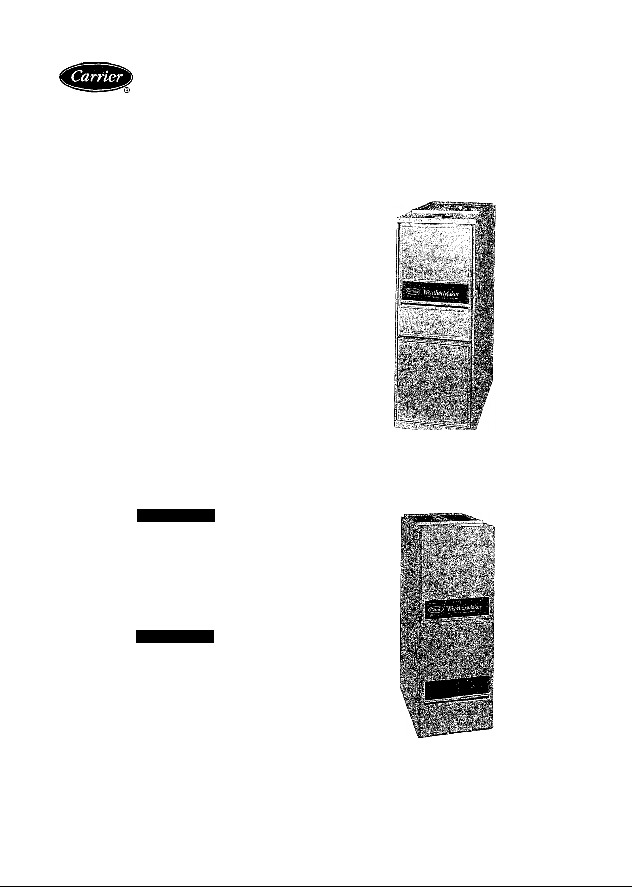
58DXC, 58SXC
Fig. 1—Model 58SXC Upflow Furnace
A91098
A
WARNING
The ability to properly perform maintenance on this equip
ment requires certain expertise, mechanical skills, tools, and
equipment. If you do not possess these, do not attempt to
perform any maintenance on this equipment other than those
procedures recommended in the User’s Manual. FAILURE
TO FOLLOW THIS WARNING COULD RESULT IN
POSSIBLE DAMAGE TO THIS EQUIPMENT, SERIOUS
PERSONAL INJURY, OR DEATH.
A WARNING
Never store anything on, near, or in contact with, the furnace,
such as;
1. Spray or aerosol cans, rags, brooms, dust mops, vacuum
cleaners, or other cleaning tools.
2. Soap powders, bleaches, waxes or other cleaning com
pounds, plastic or plastic containers, gasoline, kerosene,
cigarette lighter fluid, dry cleaning fluids, or other volatile
fluids.
3. Paint thinners and other painting compounds, paper bags or
other paper products.
Failure to follow this warning can cause corrosion of the heat
exchanger, fire, personal injury, or death.
Manufacturer reserves the right to discontinue, or change at any time, specifications or designs without notice and without incurring obligations.
Book 1 4
Tab 6a 8a
PC 101 Catalog No. 535-832
Printed in U.S.A,
Form 58D,S-8SM
Fig. 2—Model 58DXC Downflow Furnace
P0 1
7-92
A91103
Replaces: 58D,S-6SM
Page 2
CARE AND MAINTENANCE
For continuing high performance and to minimize possible equip
ment failure, it is essential that maintenance be performed annually
on this equipment. Consult your local dealer for maintenance and
the availability of a maintenance contract.
A WARNING
Turn OFF the gas and electrical supplies to the unit before
performing any maintenance or service. Follow the operating
instructions on the label attached to the furnace. Failure to
follow this warning could result in personal injury.
The minimum maintenance that should be performed on this
equipment is as follows:
1. Check and clean or replace air filter each month as required.
2. Check blower motor and wheel for cleanliness and lubrication
each heating and cooling season. Clean and lubricate as
necessary. (See Step 2.)
3. Check electrical connections for tightness, and controls for
proper operation each heating season. Service as necessary.
4. Check for proper condensate drainage; clean as necessary.
5. Check for blockages of combustion-air and vent pipes.
A CAUTION
As with any mechanical equipment, personal injury could
result from sharp metal edges, etc. Be careful when removing
parts.
Step 1—Air Filter Cleaning and Replacement
The air filter anangement may vary depending on the application.
A CAUTION
Never operate unit without a filter or with filter access door
removed. Failure to follow this warning could result in a fire
or personal injury.
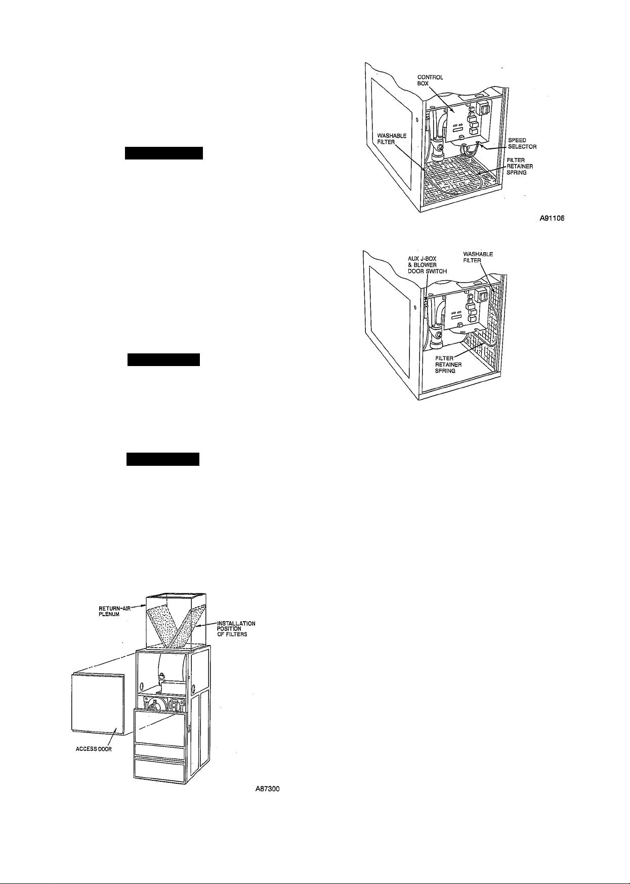
DOWNFLOW FURNACES ONLY - Each furnace accommo
dates 2 filters which are installed in the return-air duct. (See Fig.
3.) To clean or replace the filters, proceed as follows:
1. Turn OFF electrical supply to unit.
2. Remove blower access door.
Fig. 3—Position of Filters in Downflow Furnace
Fig. 4—Filter Installed for Bottom Inlet in Upflow
Furnace
A91109
Fig. 5—Filter Installed for Side Inlet in Upflow
Furnace
3. Reaching up behind top plate, tilt filters toward center-of
return-air plenum, remove filters, and replace or clean as
needed.
4. Furnaces are equipped with permanent, washable filters. Clean
these filters by spraying cold tap water through filter in
opposite direction of airflow.
5. Rinse filters and let dry. Oiling or coating of filters is not
recommended.
6. Reinstall filters with cross-mesh binding facing blower.
7. Replace access door.
8. Turn ON electrical supply to furnace.
UPFLOW FURNACES ONLY - To clean or . replace the air
filter, proceed as follows:
1. Turn OFF electrical supply to unit.
2. Remove access doors.
3. Release filter retainer spring from behind flange of furnace
casing. (See Fig. 4 and 5.)
4. Slide filter out.
5. Furnaces are equipped with permanent, washable filters. Clean
filter by spraying cold tap water through filter in opposite
direction of airflow.
6. Rinse filter and let dry. Oiling or coating of filter is not
recommended.
7. Place filter in furnace with cross-mesh binding either up or
facing blower.
8. Replace access doors.
9. Turn ON electrical supply to furnace.
WA
Page 3
step 2—Blower Motor and Wheel Maintenance
For long life, economy, and high efficiency clean accumulated dirt
and grease from blower wheel and motor annually.
The following items should be performed by a qualified service
technician;
Some motors have prelubricated, sealed bearings and require no
lubrication. These motors can be identified by the absence of oil
ports on each end of the motor. For motors with oil ports, lubricate
as follows:
Lubricate motor every 5 years if motor is used for intermittent
operation (thermostat FAN switch in AUTO position), or every 2
years if motor is in continuous operation (thermostat FAN switch
in ON position).
Clean and lubricate' as follows:
1. Turn OFF electrical supply to unit.
2. Remove access doors.
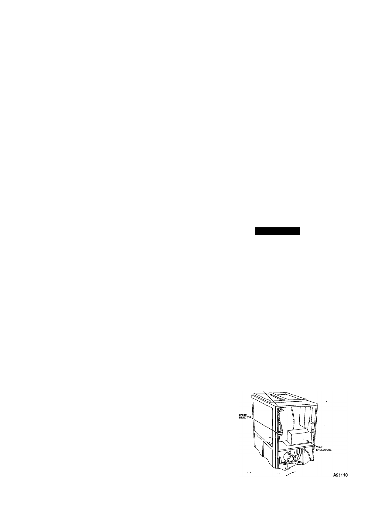
3. Downflow furnace only — disconnect vent pipe, elbow, and
auxiliary limit switch. (See Fig. 6.)
a. Remove vent pipe enclosure from top side of blower shelf
and position to 1 side.
b. Loosen hose clamps on outlet elbow and remove elbow.
c. Loosen hose clamp on extension pipe outside of furnace
and remove pipe.
d. Disconnect wires from auxiliary limit on blower housing.
4. Note location of wires for reassembly, then remove electrical
leads from numbered side of blower speed selector. (See Fig.
4 and 6.)
5. Upflow furnaces only —remove drain trap and control box.
a. Remove control box from bottom side of blower shelf and
position to 1 side.
b. Using backup wrench, disconnect drain pipe at coupling in
blower compartment.
c. Loosen hose clamp and remove 7/8-in. diameter drain hose
from drain trap.
d. Loosen hose clamp and disconnect 5/8-in. diameter drain
hose at bottom of inducer housing located under blower
shelf.
e. Remove screw securing drain trap assembly.
6. Remove screws securing blower assembly to blower shelf and
slide blower assembly out of furnace.
7. Squeeze side tabs of blower speed selector and pull from
blower housing bracket.
8. Loosen screw in strap holding motor capacitor to blower
housing and slide capacitor from strap.
9. Mark blower wheel location on shaft before disassembly to
insure proper reassembly.
10. Loosen setscrew holding blower wheel on motor shaft.
NOTE: Mark blower mounting arms, and blower housing so each
arm is positioned at the same hole location during reassembly. This
will insure that oilers point up.
11. Remove bolts holding motor mount to blower housing and
slide motor and mounts out of housing. Disconnect ground
wire attached to blower housing before removing motor.
12. Lubricate motor (when oil ports are provided).
a. Remove dust caps or plugs from oil ports located at each
end of motor. If motor does not have these caps or plugs,
bearings are sealed and need no further lubrication.
b. Use a good grade of SAE 20 nondetergent motor oil and
add 1 teaspoon (5 cc, 3/16 oz, or 16 to 25 drops) in each oil
port. The use of other types or grades of oil will damage the
motor. Excessive oiling can cause premature bearing fail
ures.
c. Allow time for total quantity of oil to be absorbed by each
bearing.
d. After oiling motor, wipe excess oil from motor housing.
e. Replace dust caps or plugs on oil ports.
13. Remove blower wheel from housing.
a. Mark blower wheel orientation and cutoff plate location to
insure proper reassembly.
b. Remove screws securing cutoff plate and remove cutoff
plate from housing.
c. Remove blower wheel from housing.
14. Clean blower wheel and motor by using a vacuum with soft
brush attachment. Be careful not to disturb balance weights
(clips) on blower wheel vanes. Do not drop or bend wheel as
balance will be affected.
15. Reassemble blower by reversing items 13.a. through 13.c.
Ensure wheel is positioned for proper rotation.
16. Reassemble motor and blower by reversing items 6 through
11. If motor has ground wire, be sure it is reconnected.
A CAUTION
Ensure the motor is properly positioned in the blower
housing. The motor oil ports must be at a minimum of 30°
above the horizontal centerline of the motor after the blower
assembly has been reinstalled in the furnace.
17. Reinstall blower assembly in furnace.
18. Upflow furnace only—reinstall drain trap and control box.
a. Inspect drain trap and hoses to ensure they are not blocked
or restricted. Reinstall drain trap and hoses. Be sure to
tighten hose clamps.
b. Using backup wrench, attach drain pipe and tighten com
pression coupling.
c. Reinstall control box on bottom side of blower shelf. Be
sure edge connector is connected through top of blower
shelf.
19. Downflow furnace only — reconnect vent pipe, elbow, and
auxiliary limit switch.
a. Reinstall outlet elbow and extension pipe. Be sure connec
tions are tight and leak proof.
AUXILIARY
LIMIT
SWITCH
Fig. 6—Model 58DXC Downflow Furnace
Page 4

b. Reinstall vent pipe enclosure.
c. Reconnect red wires to auxiliary limit switch.
20. Connect electrical leads to blower speed selector. Note that
connections are polarized for correct assembly — do not force.
21. Turn ON electrical supply and check for proper rotation and
speed changes between heating and cooling; operate unit 5
minutes and carefully check for condensate leaks.
Step 3—Cleaning Heat Exchangers
The following items should be performed by a qualified service
technician:
If it becomes necessary to clean the heat exchanger because of
carbon deposits, soot, etc., proceed as follows:
NOTE: Deposits of soot and carbon indicate a problem exists that
needs to be corrected. Action must be taken to correct the problem.
1. Turn OFF gas and electrical supplies to furnace.
2. Remove control and blower access doors.
3. Loosen hose clamps on combustion-air pipe and move air pipe
aside.
4. Using backup wrench, disconnect gas supply at ground joint
union. Remove gas pipe from valve.
5. Disconnect hot surface ignitor and flame sensor leads at
3-circuit connector outside of burner enclosure.
6. Disconnect electrical wires from gas valve.
7. Disconnect pressure tubing from right side of burner enclosure
and outlet end of gas valve.
8. Remove burner enclosure front.
9. Remove diffuser from inside top of burner enclosure. Remove
screws that secure burner enclosure to cell panel. These
screws are located inside the burner enclosure.
10. Using care not to damage cell inlet panel gasket, remove gas
control assembly from furnace.
11. Remove vent pipe and drain.
a. Upflow furnace only:
(1.) Loosen hose clamps at vent pipe connection; discon
nect vent pipe and position to 1 side.
(2.) Loosen hose clamp and remove drain tube from
inducer outlet box.
b. Downflow furnace only:
(1.) Remove vent pipe enclosure.
(2.) Loosen hose clamps at vent pipe connection.
(3.) Loosen hose clamp and remove drain tube from
inducer outlet elbow.
12. Upflow furnace only —remove main control box.
a. Disconnect edge connector from main control box at
blower shelf.
b. Remove screws securing main control box to blower shelf
and position control box to 1 side.
13. Disconnect inducer motor connector from wiring harness.
Disconnect wires and pressure tube from pressure switch.
14. Loosen hose clamp and remove drain tube from inducer
housing.
15. Remove mounting screws securing inducer assembly to col
lector box and coupling box; remove inducer assembly.
16. Remove all old sealant from parts.
17. Remove coupling box(es).
a. Upflow furnace only:
(1.) Remove screws securing coupling box and remove
from furnace. Remove all old sealant from parts.
(2.) Remove choke plate (when used) from primary heat
exchanger outlet.
b. Downflow furnace only:
(1.) Remove screws securing intake (upper) coupling box
and remove from furnace. Remove all old sealant from
parts. ^
(2.) Remove screws securing primary (lower) coupling
box and remove box. Clean old sealant from parts.
18. Loosen hose clamp and remove 7/8-in. drain tube from trap.
19. Hold bucket under 7/8-in. drain tube.
20. Using garden hose, flush each cell of the condensing heat
exchanger with water. Use care not to spray water onto
interior surfaces of control compartment. Dry all surfaces. Be
careful not to remove sealant around cell openings in cell
panel.
21. Using field-provided small wire brush, steel spring cable,
reversible electric drill, and vacuum cleaner, clean primary
heat exchanger cells. Do not use wire brush or other sharp
object to clean condensing heat exchanger. Failure of the
condensing heat exchanger will occur—flush with water only.
a. Assemble wire brush and steel spring cable.
(1.) Use 4 ft of 1/4-in. diameter high-grade steel spring
cable (commonly known as drain cleaning or RotoRooter cable).
(2.) Use 1/4-in. diameter wire brush (commonly known as
25-caIiber rifle cleaning brush).
NOTE: The materials required in items (1.) and (2.) can be
purchased at local hardware stores.
(3.) Insert twisted wire end of brush into end of spring
cable, and crimp tight with crimping tool or strike with
ball-peen hammer. Tightness is very important.
(4.) Remove metal screw fitting from wire brush to allow
insertion into cable.
b. Clean each primary heat exchanger cell.
(1.) Attach variable-speed, reversible drill to end of spring
cable (end opposite brush).
(2.) Insert brush end of cable into upper opening of cell
and slowly rotate with drill. Do not force cable.
Gradually insert at least 3 ft of cable into 2 upper
passes of cell. (See Fig. 7.)
A884S9
Fig. 7—Cleaning Primary Heat Exchanger Cell
(3.) Work cable in and out of cell 3 or 4 times to obtain
sufficient cleaning. Do not pull cable with great force.
Reverse drill and gradually work cable out.
(4.) Insert brush end of cable in lower opening of cell, and
proceed to clean 2 lower passes of cell in same manner
as 2 upper passes.
Page 5

(5.) Repeat procedures (above) until each furnace cell has
been cleaned.
(6.) Using vacuum cleaner, remove residue from each cell.
' (7.) Using vacuum cleaner with soft brush attachment,
clean burner assembly.
Step 4—Reassemble Furnace (After Cleaning Heat Ex
changers)
1. Install choke plate (when used). Be sure choke plate bottom
conforms to top flange of condensing heat exchanger.
2. Reinstall coupling box(es);
a. Apply sealant releasing agent (Pam) to cell panel where
coupling box flange matches. (See Fig. 8.)
b. Apply a generous bead 3/16-in. dia) of G.E. RTV 122,162,
or Dow-Corning RTV 738 sealant (NO substitute is
permissible) to flange of coupling box. Your distributor
should have G.E. RTV 122, 162, or Dow-Corning RTV
738 sealants in stock.
c. Being careful not to smear sealant, position coupling box so
that slot in insulation is on left side and install coupling
box.
APPLY RELEASE AGENT TO AREA
INDICATED BY SHADING
A86100
Fig. 9—Backside of Inducer Assembly Housing
COUPLING BOX
(INSIDE VIEW)
A87318
Fig. 8—Inside View of Coupling Box
NOTE: Downflow furnace only—position primary (lower) cou
pling box so that tallest end is on right side.
3. Reinstall inducer assembly.
a. Upflow furnace only —Be sure small round gasket(s) is in
place between blower shelf and inducer housing.
b. Apply sealant releasing agent (Pam) to collector box. (See
Fig. 9.)
c. Apply 1/8-in. diameter bead of G.E. RTV 122, 162, or
Dow-Corning RTV 738 sealant to back of inducer housing.
Apply sealant around inlet air opening. (The sealant should
be about 1/4 in. from the edge of the inlet air opening.)
d. Install inducer assembly on collector box and support
bracket to coupling box.
e. Connect inducer motor plug-in connector to wiring har-
ness.Reconnect wires to pressure switch using furnace
wiring diagram. (See Fig. 17.)
f. Reconnect pressure tubes to pressure switch. (See Fig. 13 or
14.)
4. Connect small drain tube from top of trap to fitting on bottom
of inducer housing. (See Fig. 13 or 14.)
BURNER FUME
5. Connect 7/8-in. drain tube to trap and collector box, and
tighten hose clamps. (See Fig. 13 or 14.)
6. Reinstall vent pipe and drain tube.
a. Upflow furnace only:
(1.) Reconnect vent pipe. Be sure clamps are tight.
(2.) Connect drain tube from collector box to inducer
outlet box.
b. Downflow furnace only:
(1.) Reconnect vent pipe. Be sure clamps are tight..
(2.) Reinstall vent pipe enclosure.
(3.) Connect drain tube from collector box to inducer
outlet elbow.
7. Upflow furnace only—reinstall main control box.
a. Reinstall main control box on blower shelf.
Page 6

13/32"-
'Vaa"
\X
1b
B
IF
il—fl
/
' IGNITOR
ASSEMBLY
K
/
Ig IGNITOR
(g BURNER
\
IGNITOR
ASSEMBLY
Fig. 12—Position of Ignitor to Burner
^8 OD
PRESSURE
TUBING
HEAT EXCHANGER
DIFFERENTIAL
PRESSURE
SWITCH
% OD
PRESSURE
TUBING
VZ OD
DRAIN
TUBING
(TUBE PASSES
THROUGH
BLOWER SHELF)
■DRAIN
TRAP
A91113
Fig, 13—Upflow Furnace Pressure and Drain Tub
ing Diagram
b. Reconnect edge connector at main control box on blower
shelf.
8. Check condition of gasket on cell inlet panel of burner
enclosure. Replace gasket if necessary. (See Fig. 10.)
9. Install gas control assembly in furnace.
10. Install diffuser and burner enclosure front.
11. Reconnect hot surface ignitor and flame sensor leads at
3-circuit connector. .
12. Refer to furnace wiring diagram and connect wires to gas
valve. (See Fig. 17.)
13. Reconnect pressure tubes to gas valve and burner enclosure.
Be sure tubes are not kinked.
14. Using backup wrench, install gas pipe in gas valve.
A91064
HEAT EXCHANGER
DIFFERENTIAL
FRESSURE
SWITCH
A91112
Fig. 14—Downflow Furnace Pressure and Drain
Tubing Diagram
15. Reconnect gas pipe at ground joint union.
16. Reconnect combustion-air pipe. Tighten hose clamps.
17. Replace blower door only.
18. Turn ON gas and electrical supplies.
19. Check furnace operation through 2 complete operating cycles.
Look through sight-glass in burner enclosure to check burners.
Burner flames should be clear blue, almost transparent. (See
Fig. 11.)
A WARNING
Never use matches, candles, flame, or other sources of
ignition to check for gas leakage. Use a soap-and-water
solution. Failure to follow this warning could result in a fire,
personal injury, or death.
20. Check for gas leaks.
21. After condensate starts to drain, check for condensate leaks.
22. Replace control door.
Step 5—Clean Condensate Drainage System
1. Disconnect 5/8-in. drain tube from bottom of inducer housing.
(See Fig. 13 or 14.)
2. Disconnect 7/8-in. drain tube from collector box. (See Fig. 13
or 14.)
3. Disconnect condensate drain line from drain trap at compres
sion fitting.
4. Remove two 1/4-in. screws securing strap on drain trap to:
a. blower housing (upflow furnaces only).
b. bracket from cell panel (downflow furnaces only).
5. Remove drain trap/hose assembly from furnace and flush with
water until clean.
6. Flush external condensate drain line with water until clean.
7. Reassemble condensate drainage system by reversing items 1.
through 5.
Step 6—Hot Surface Ignitor
When removing the burner assembly, use care to avoid breaking
the hot surface ignitor. See Fig. 12 for the conect ignitor
Page 7

__________
FIELD 24-VOLT WIRING
— —FIELD 115-, 208/230-, 460-VOLT WIRING
FACTORY 24-VOLT WIRING
FACTORY 115-, 208/230-, 460-VOLT WIRING
(w>-
e>-
(¡>-
115-VOLT
SINGLE
PHASE
—^-»-rrn-
-JL—
■=*GND
115-VOLT
FIELD-SUPPLIED
FUSED DISCONNECT
----
1^0
AUXILIAHY
J-BOX
o^-
-VOLT
Fig. 15—Heating and Cooiing Appiication Wiring Diagram
location. When reinstalling ignitor, use care to insure all wiring is
away from the burners and is not touching the bottom of the sheet
metal enclosure.
Step 7—Electrical Controls and Wiring
NOTE; There may be more than 1 electrical supply to the unit.
The electrical ground and polarity for 115-v wiring must be
maintained properly. Refer to Fig, 15 for field wiring information
and to Fig. 17 for unit wiring information. If the polarity is not
correct, the microprocessor control will shut off the gas flow
shortly after completion of the ignition trial period. The control
system also requires an earth ground for proper operation of the
niicroprocessor.
The 24-v circuit contains an automotive-type, 3-amp fuse (FUl)
located on the main control board. (See Fig. 16.) Any direct shorts
during installation, service or maintenance may cause this fuse to
"blow." If fuse replacement is required, use only a fuse of identical
size.
With power disconnected to the unit, check all electrical connec
tions for tightness. Tighten all screws on electrical connections. If
any smokey or burned connections are found, disassemble the
connection, clean all parts, strip wire, and reassemble properly and
securely.
Reconnect electrical power to the unit and observe unit through 1
complete operating cycle. Electrical controls are difficult to check
without proper instrumentation; if there are any discrepancies in
the operating cycle, contact your dealer and request service.
NOTES:
1. CONNECT Y-TERMINAL AS SHOWN FOR PROPER COOLING OPERATION.
2. IF ANY OF THE ORIGINAL WIRE, AS SUPPLIED, MUST BE REPLACED,
USE SAME TYPE OR EQUIVALENT WIRE.
3. PROPER POLARITY MUST BE MAINTAINED FOR 115-VOLT WIRING.
Step 8—Winterizing
A CAUTION
The unit must not be installed, operated, and then turned off
and left off in an unoccupied structure during cold weather
when the temperature drops to 32° F and below. Freezing
condensate left in the furnace will damage the equipment.
If the furnace will be off for an extended period of time in a
structure where the temperature will drop to 32° F or below,
winterize as follows;
1. Mix a solution of equal amounts of ethylene glycol (Prestone
II antifreeze/coolant or equivalent) and water.
2. Turn OFF electrical supply to furnace.
3. Remove control access door.
4. Disconnect drain tube from bottom of inducer outlet box/el-
bow.
5. Insert funnel in drain tube and pour antifreeze/water solution
into furnace until it is visible at point where condensate enters
open drain.
6. Reconnect drain tube to outlet box/elbow.
7. Replace control access door.
ELECTRONIC
AIR CLEANER
TERMINALS
A87502
Page 8

TO 115VAC FIELD DISCONNECTIONS
HUM-1 (TPl)
0=
BLWR
HSIR
I NOTE #5
j EQUIPMENT GROUND
SCHEMATIC DIAGRAM
(NATURAL GAS S PROPANE)
GVR
RED
YEL
Otpb
OtP7
W Y R C G
0 0 0 0 0
0_R
LEGEND
ALS
AUXILIARY LIMIT SWITCH, OVERTEMP.-
BLWR
BLOWER MOTOR RELAY, SPST-(N.O.)
BLWM
BLOWER MOTOR
CAP
CAPACITOR
CPU
MICROPROCESSOR AND CIRCUITRY
EAC-1
ELECTRONIC AIR CLEANER CONNECTION (115 VAC 1 AMP MAX.)
EAC-2
ELECTRONIC AIR CLEANER CONNECTION (COMMON)
FR5
FLAME ROLLOUT SWITCH
FSE .
FLAME SENSING ELECTRODE
FUl
FUSE, 3 AMP, AUTOMOTIVE BLADE TYPE, FACTORY INSTALLED
FU2
FUSE, FIELD INSTALLED
GV
GAS VALVE-REDUNDANT OPERATORS
6VR
MAIN GAS VALVE RELAY, DPST-(N.O.)
HI/LO
BLOWER MOTOR SPEED CHANGE RELAY, DPST-(N.O.)
H5!
HOT SURFACE IGNITOR (115 VAC)
HSIR
HOT SURFACE IGNITOR RELAY, DPST-(N.O.)
HUM-1
24VAC HUMIDIFIER CONNECTION (.5 AMP. MAX.)
HUMR
HUMIDIFIER RELAY, DPST-(N.O.) -
!DM ■
INDUCED DRAFT MOTOR
I DR
INDUCED DRAFT RELAY, DPST-(N.O.)
ILK
BLOWER DOOR INTERLOCK SWITCH, 5PST-(N.O.)
JB
JUNCTION BOX
JH9
INDUCER OFF DELAY JUMPERi CUT-15 SEC DELAY, UNCUT -5 SEC DELAY
LGPS
LOW GAS PRESSURE SWITCH, SPST-(N.O.)
LS
LIMIT SWITCH, OVERTEHPERATUR^-AUTO RESET, 5PST-(N.C.)
PCB
PRINTED CIRCUIT BOARD
PLl
11-CIRCUIT EDGE CONNECTOR (PCB)
24V AC
COMMON
nCX
MANUAL RESET, SP5T-CN.C.)
HUM-1 (TP
.5 AMP. MAX.
DELAY
HUMR
0
JW9 NOTE /8
SELF
CPU
BLOWER OFF
^ ^ ^ ^
90 135 180 225 I® ^
NOTE #7 STl ST2
>—I
GROUND SCREW REQUIRED
NOTE #1
PC8
PL2 2-ClRCUIT HSI CONNECTOR
PL3 2-CIRCUlT I DM CONNECTOR
PL4 1-CIRCUIT FSE CONNECTOR
PL5 5-CIRCUIT BLWM CONNECTOR
PL6 3-CIRCUIT FSE/HSI CONNECTOR
PRS PRESSURE SWITCH, 5PST-(N.O.)
ST1-ST2 SELF TEST PINS
TP1-TP7 TEST POINT (1) THRU (7)
TRAN TRAN5F0RMER-115VAC/24VAC
JUNCTION
UNMARKED TERMINAL
o
PCB TERMINAL
MARKED TERMINAL
5
FACTORY WIRING (11SVAC)
FACTORY WIRING (24VAC)
FIELD WIRING CllSVAC)
FIELD WIRING (24VAC)
CONDUCTOR ON PCB
FIELD WIRING SCREW TERMINAL
FIELD GROUND
EQUIPMENT GROUND
FIELD SPLICE
PLUG RECEPTACLE
Fig. 17—^Wiring Diagram
NOTES:
1. COMMON SIDE (5EC-2 AND C) OF 24VAC TRANSFORMER CONNECTED TO
GROUND THROUGH THIS REQUIRED MOUNTING SCREW.
2. IF ANY OF THE ORIGINAL EQUIPMENT WIRE IS REPLACED USE WIRE
RATED FOR lOS-C.
3. INDUCER (lOM) AND BLOWER CBLWM) MOTORS CONTAIN INTERNAL
AUTO-RESET THERMAL OVERLOAD SWITCHES.
4. BLOWER MOTOR SPEED SELECTIONS (PL5) ARE FOR AVERAGE CONDITIONS
SEE INSTALLATION INSTRUCTIONS FOR DETAILS ON OPTIMUM SPEED
SELECTION.
5. USE ONLY COPPER WIRE BETWEEN THE DISCONNECT SWITCH-AND THE
FURNACE JUNCTION BOX CJB).
6. AUXILIARY LIMIT SWITCH CALS) USED ON DOWNFLOW MODELS ONLY
7. BLOWER MOTOR (BLWM) ADJUSTABLE OFF-DELAY.
8. JW9 TO BE CUT FOR IS-SEC. INDUCER POST-PURGE FOR CONDENSING
FURNACES.
9. FACTORY CONNECTED WHEN LGPS NOT USED.
10. REPLACE ONLY WITH A 3 AMP FUSE. 317275-401 REV. B
A91063
Page 9

START
TROUBLESHOOTING GUIDE
HSI CONDENSING FURNACES
Page 10

Copyright 1992 CARRIER Corp. • 7310 W. Morris St. ■ Indianapolis, IN 46231
Manufacturer reserves the right to discontinue, or change at any time, specifications or designs without notice and without incurring obligations.
Book 1 4
Tab 6a 8a
PC 101
Catalog No. 535-832
Printed in U.S.A. Form 58D,S-8SM Pg 10
7-92 Replaces: 58D,S-6SM
15063
 Loading...