

Page 1
58DX
HEATING A COOLING
Deluxe Downflow Condensing Furnaces
Installation, Start-Up and Service Instructions
For Sizes 040-100
NOTE: Read these instructions carefully and completely
before installing the furnace.
INTRODUCTION
Before installing the furnace, refer to “Procedure for Down
flow Condensing Furnaces” (packaged with the equipment)
for information concerning combustion, venting, piping, and
other standard installation practices. Further reference is
made to the current edition of the National Fuel Gas Code
NFPA 54-1988-1/ANSI Z223.1-1988.
>• Reference should eJso be made to the regulations of the
serving gas supplier and the local building, heating, plumb
ing, or other codes in effect in the area in which the installa
tion is made.
SAFETY CONSIDERATIONS
Installation emd servicing of heating equipment can be haz
ardous due to gas and electrical components. Only treiined
and qualified personnel should install, repair, or service
heating equipment.
Untrained personnel cem perform basic maintenance func
tions such as cleaning and replacing air filters. AU other
operations must be performed by trained service personnel.
When working on heating equipment, observe precautions
in the literature, tags, and labels attached to or shipped
with the unit and other safety precautions that may apply.
FoUow aU safety codes, including NFPA No. 54/ANSI
Z223.1-1988, National Fuel Gas Code, Wear safety glasses
and work gloves. Have fire extinguisher available during
startup and adjustment procedures and service call.
Recognize safety information. This is the safety-alert sym
bol A. When you see this symbol on the furnace and in
instructions or manuals, be alert to the potential for per
sonal injury.
Understand the signal word—DANGER, WARNING or
CAUTION. These words are used with the safety-alert sym
bol. DANGER identifies the most serious hazards which
will result in severe personal injury or death. WARNING,
on the other hand could result in personal injury or death.
CAUTION is used to identify unsafe practices, which would
result in minor personal injury or product and property
damage.
Each Model 58DX is shipped from the factory completely
assembled with a multispeed direct-drive blower and wired
ready for an indoor heating installation. The furnace fea
tures a blower control center with easy-to-read, 24-volt ter
minal strip to ensure proper connections.
The output capacity and any representations of efficiency
for this furnace aie based on standard Department of
Energy test procedures.
The installed operation may vary, depending on installation,
weather, and other factors.
The design of the downflow gas-fired furnace is A.G.A. cer
tified for installation on noncombustible flooring. The fur
nace may be installed on combustible flooring when
installed with the accessory downflow subbase. This furnace
is designed for installation in alcoves, attics, basements,
closets, utility rooms, and manufactured housing (mobile
homes). This furnace line is not A.G.A. certified for installa
tion in a recreation vehicle or outdoors.
■ EFFICIENCY
■ RATING
I CERTIFIED
lama
Fig. 1 —Model 58DX
A WARNING
Improper installation, adjustment, alteration, service,
maintenance, or use can cause carbon monoxide poison
ing, explosion, fire, electrical shock, or other conditions
which may cause personeJ injury or property damage.
Consult a qualified installer, service agency, local gas
supplier or your Distributor or Branch for information
or assistance. The qualified installer or agency must use
only factory authorized kits or accessories when modi
fying this product. A failure to adhere to this warning
can cause electrical shock, fire, personal injury, or
death.
Series
A87414
Manufacturer reserves the right to discontinue, or change at any time, specifications or designs without notice and without incurring obligations.
Book] 1 I 4 PC 101 Catalog No. 535-887 Printed in U.S.A. Form 58DX-13Si Pg 1 6-89 Repiaces; 58DX-11Si
Tab I6al8a
Page 2
HOLE IN
FLOOR
3
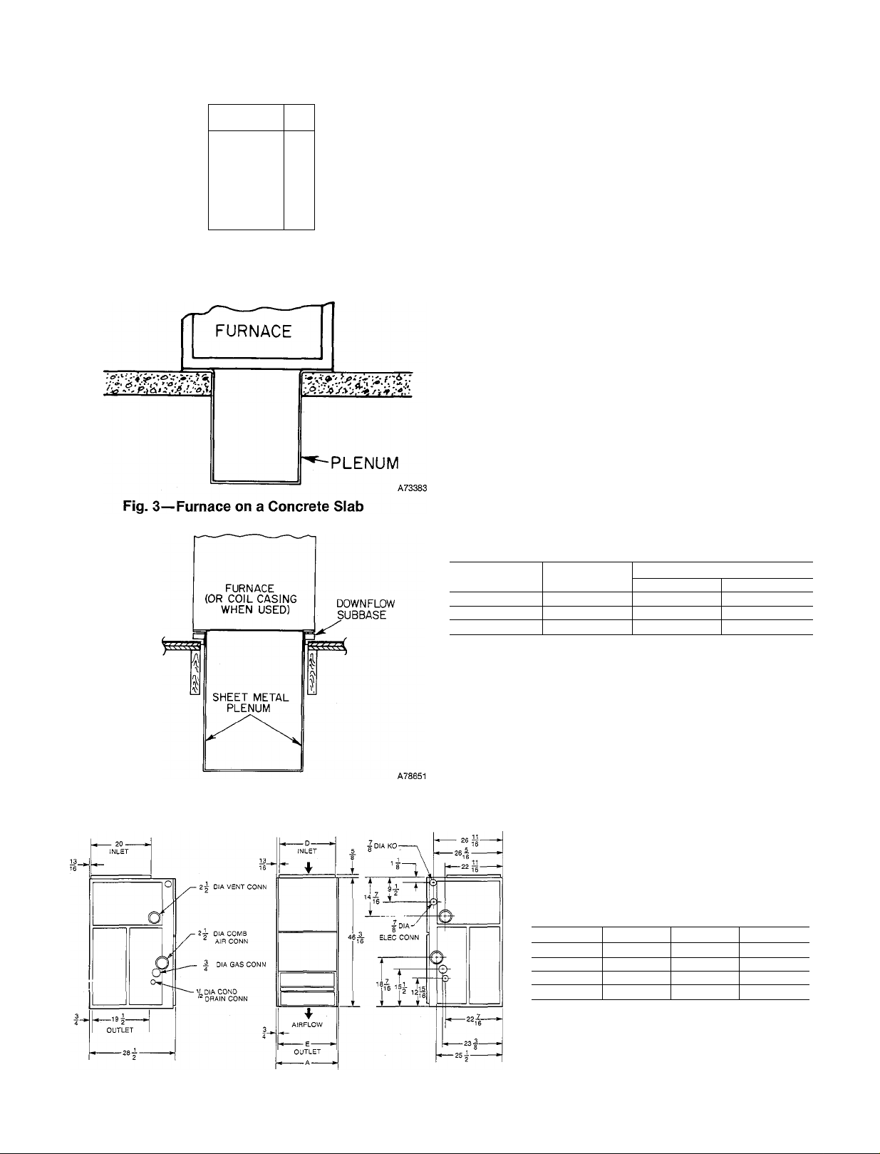
Fig. 2—Floor Opening for Concrete Slab
Insteillation requires the following;
*1. Inspection
*11. Furnace Location
*III. Gas Piping
*IV. Combustion-Air and Vent Piping
*V. Condensate Piping
VI. Supply-Air Plenum Installation
VII. Electrical
VIII. Sequence of Operation
IX. Fdter
*X. Startup and Adjustment
XI. Care and Maintenance
*For these sections (or installation steps), refer to the appro
priate sections of “Procedures for Downflow Condensing
Furnaces” booklet packaged with this unit.
For accessory instedlation details, refer to the applicable
installation hterature.
NOTE: Remove all shipping brackets and materials before
operating the furnace.
VI. SUPPLY-AIR PLENUM INSTALLATION
A. Installation on a concrete slab
1. See Fig. 5 for dimensions and location of supply-air
opening in furnace bottom.
2. Construct hole in floor per dimensions in Fig. 2 and
Table 1.
3. Place plenum and furnace as shown in Fig. 3.
Fig. 4—Furnace, Plenum, and
Base Installed on a Combustible Floor
Table 1—Opening Dimensions
Furnace A
Width
171/2
21
241/2
*These dimensions appiy when a Model 28RC or 28RD Evaporator Coil
casing is to be installed.
16 1/8
19 5/8 19 5/8
231/8
Furnace
19 5/8 19 7/16
19 5/8 19 7/16
B. Installation on a combustible floor
B
Furnace & Coil*
19 7/16
1. Read Installation Instructions packaged with down
flow subbase.
2. Cut and frame hole in floor per dimensions in Installa
tion Instructions packaged with downflow subbase. If
this requires cutting of a floor joint, tie ends of cut
joist into adjacent joists so that proper floor support
wUl be maintained.
Table 2—Dimensions (In Inches)
Size A D E
040 171/2 15 7/8 16
060
080 21 19 3/8 191/2
100 24 1/2 22 7/8 23
171/2 15 7/8 . 16
WA
A87297
Fig. 5—Dimensional Drawing
2
Page 3
------------------
FIELD 24-VOLT WIRING
TERMINAL BLOCK
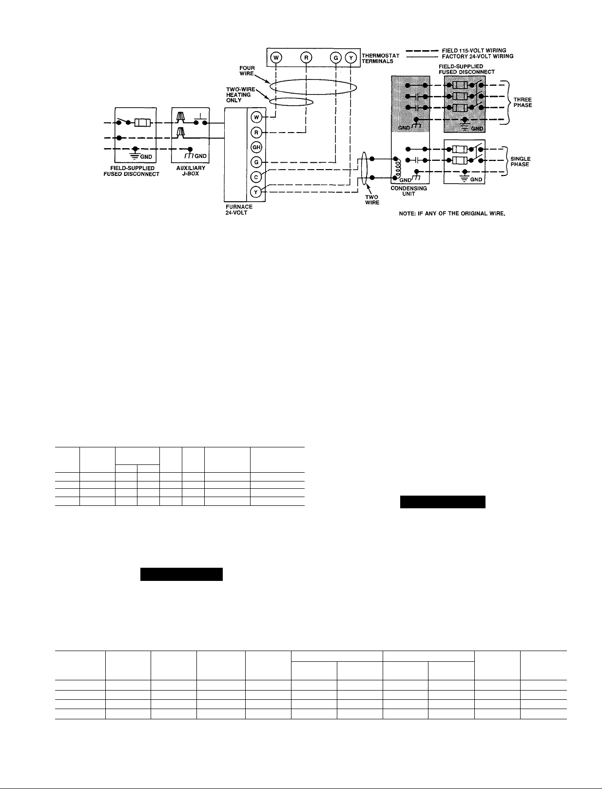
Fig. 6—Heating and Cooiing Application Wiring Diagram
3. Assemble and install downflow subbase per instruc
tions packaged with subbase.
4. When completed, downflow subbase, plenum, and fur
nace (or coil casing when used) should be installed as
shown in Fig. 4.
VII. ELECTRICAL CONNECTIONS
A. 115-Volt Wiring
iM PORT ANT: Before proceeding with the electrical connec
tions, make certain that voltage, frequency, and phase cor
respond to that specified on the unit rating plate and Table
3. Also, check to be sure that the service provided by the
utility is sufficient to handle the load imposed by this equip
ment. Refer to Table 3 for the equipment electrical
specifications.
Table 3—Electrical Data
Volts-
SIZE Hertz- Voltage Range
Phase Max* Min*
040 115—60—1 127 104
060
115—60—1
080 115—60—1 127 104
100 115—60—1 127 104
»Permissible limits of the voltage range at which the unit will operate sat
isfactorily.
fTime-delay fuse is recommended.
^Length shown is as measured one way along wire path between unit
and service panel for maximum 2% voltage drop.
Operating
127 104
Max. Min.
Unit Wire Length HACR-Type
Amps Size Feett Ckt Bkr Amps
8.7 14 41 15
8.2 14 42 15
10.1 14 36 15
13.6 12 42 20
Max. Wire
Max. Fusef or
A CAUTION
Do not connect aluminum wire between the disconnect
switch and the furnace.
AS SUPPLIED, MUST BE REPLACED, USE
SAME TYPE OR EQUIVALENT WIRE.
A87502
See Fig. 6 for a wiring diagram showing the proper field
115- and 24-volt wiring. Be sure field wiring complies with
the National Electric Code and any local codes or ordnances
that may apply. Voltage to the furnace must be within the
limits shown in Table 3. Contact your local power company
for correction of improper voltage.
NOTE; Operation of unit on improper line voltage consti
tutes abuse and could affect unit reliability. Do not install
the furnace in a system where voltage may fluctuate above
or below permissible limits.
Use a separate fused branch electrical circuit containing the
properly sized time-delay fuse or HACR-type circuit breaker
for this furnace. See Table 3 for fuse and wire specifications.
A disconnecting means must be located within sight of, and
readily accessible to, the furnace. The blower door switch
may be acceptable in some areas as a disconnecting means.
Line voltage must enter the auxiliary J-box on the righthand side of the furnace.
A WARNING
The cabinet must have an uninterrupted or unbroken
ground according to National Electrical Code. ANSI/
NFPA 70-1987, or local codes to minimize personal
injury if an electrical fault should occur. This may con
sist of electrical wire or conduit approved for electrical
ground when installed in accordance with existing elec
trical codes. Do not use gas piping as an electrical
ground. A failure to adhere to this warning can result in
an electrical shock, fire, or death.
Table 4—Ratings and Performance
Indoor
SIZE
040
060
080
100 110,000 101,000 100,000 40—70
*Gas input ratings are certified for elevations to 2000 ft. For elevations above 2000 feet, reduce ratings 4% for each 1000 ft above sea level.
tDetermined by U.S. Government tests.
»»Isolated combustion system; GAMA non-weatherized.
input
Btuh*
44,000
66,000 60,000
88,000 81,000 80,000 40—70
Capacity
Btuht
40,000 40,000 20—50 0.10 1335
ICS»*
Capacity
Btuht
60,000
Temperature
Rise
Range
40—70
Heating Cooling
Ext Static
Pressure
0.12 1275
0.15 1590
0.20 2000
Cfm
Ext Static
Pressure
0.5 1265 1/3 PSC
0.5 1170 1/3 PSC
0.5 1565 1/2 PSC
0.5 2035
Cfm
HP & Type
Motor
3/4 PSC 241
Approx
Shipping
Weight
179
187
202
Page 4

A CAUTION
If a manual disconnect switch is to be mounted on the
furnace, select a location where a drill or fastener will
not come in contact with electrical or gas components.
Check all electrical connections (both factory and field)
for tightness. This check should also be done after the
unit has reached operating temperatures.
If 115-volt wiring to the unit is encased in a nonmetallic
sheath, connect the incoming ground wire to the grounding
wire inside the furnace J-box. If properly grounded metallic
conduit is used, it will serve as the furnace ground.
B. 24-Volt Wiring
Make field 24-volt connections at the 24-volt terminal strip.
See Fig. 6.
NOTE: Use AWG No. 18 “color-coded” copper thermostat
wire for lengths up to 100 ft. For wire lengths over 100 ft,
use AWG No. 16 wire.
IMPORTANT: The thermostat heat anticipation must be
set to match the amp draw of the gas valve and other elec
trical components in the R-W circuit. The amp reading
should be taken after the blower has started. The room ther
mostat should be located where it will be in the natural cir
culation path of room air. Avoid locations where the ther
mostat would be;
1. Exposed to cold-air infiltration.
2. Exposed to drafts from windows, doors, or other open
ings leading to the outside.
3. Exposed to air currents from warm- or cold-air
registers.
4. Located behind doors, above or below shelves, mantels,
or any other location where the natural circulation of
air is cut off.
5. Exposed to heat from fireplaces, radios, televisions,
lamps, or the rays of the sun.
6. Located on a wall containing pipes or warm-air ducts,
or flue or vent pipes.
7. Located on a wall that is inadequately sealed from the
attic, crawlspace, or basement.
Any hole in the plaster or panel through which the wires
pass from the thermostat should be adequately sealed with
suitable material to prevent drafts from affecting the
thermostat.
C. Blower Control Center
Each furnace features a blower control center. This device
will aid the installer and service technician when installing
or servicing the unit. A 24-volt terminal strip is marked for
easy connection of field wiring. See Fig. 7.
The blower control center features an adjustable blower-off
timing device. The “off” timing delay cem be varied over a
range of 80 to 240 seconds by turning the “off” timing
adjustment control in the direction indicated on the label
attached to the side of the control box. After a change in
adjustment, the time-delay circuit must be energized at
least 4 minutes to achieve the new “off” time delay setting.
The “off” timing adjustment is set at the factory for a delay
of approximately 240 seconds. See Fig. 7. The on-time delay
is not adjustable (60 seconds).
VIII. SEQUENCE OF OPERATION
Heating Cycle
The control circuit of the furnace shown in the schematic
wiring diagram. Fig. 8, results in the following sequence of
Km
Fig. 7—Blower Control Center
operation for the heating cycle:
When the blower door is in place, 115 VAC is supplied
through blower door interlock switch ILK. Trans
former TRAN is energized, supplying 24 VAC to heat
ing blower relay HFR, which opens normally-closed
blower relay contacts HFR in the low-speed circuit of
blower motor MTR.
The wall thermostat “calls for heat,” closing thé R and
2.
W circuit. This closed circuit supplies power to the 24VAC safety circuit containing automatic reset limit
switch LSI and manual reset auxüiary limit switch
LS2. Auxiliary limit switch LS2 will break electrical
circuit to gas valve if blower compartment or filters
overheat. The switch must be manually reset after
cause of overheat condition is corrected.
3. The inducer motor relay coU IDR is energized. Inducer
motor relay contacts in the 115-VAC circuit close,
starting inducer motor IDM. Simultaneously, another
set of contacts in inducer motor relay IDR close in the
24-VAC circuit, and lock in inducer motor relay coil
IDR. The coil is locked in until the R and W circuit or
safety circuit opens.
4. As inducer motor IDM comes up to speed, flow sensing
switch AFS actuates energizing the PILOT solenoid
coil of gas valve GV and the time-delay relay in spark
generator ICP through fusible link FL.
When the PILOT solenoid coil is energized, gas flows
5.
to the pilot. The internal pressure switch within gas
valve GV senses the pilot gas pressure and closes, com
pleting the HOLD circuit. The normally open timedelay relay within spark generator ICP closes after a
10-second purge delay, energizing spark generator. The
pilot gas is ignited by a spark produced by spark
generator.
After a short time delay, during which the pilot flame
6.
heats up flame sensing contacts PS, the normedly
closed contacts PS open. The PILOT solenoid coil
remains energized through the HOLD circuit. Spark
generator ICP shuts off when flame is sensed at the
spark electrode. The normally open flame-sensing con
tacts PS close 5 to 20 seconds later, energizing the
MGV solenoid coil of the GV. Six to 15 seconds later,
the MGV solenoid opens, allowing gas to flow to the
main burners where the gas is ignited by the pilot
flame.
7. Simultaneously, time-delay circuit AR in the blower
control center is energized. Approximately 50 seconds
A87298
I
Page 5

Page 6

after MGV solenoid coil is energized, heating relay coil
HFR is deenergized, closing the 115-VAC contacts of
heating relay HFR and steirting blower motor MTR on
heating speed. The H terminal is energized with 24
VAC when the blower motor is operating on heating
speed. Electronic air cleaner terminals (EAC) are ener
gized with 115 VAC when the blower is operating on
either heating or cooHng speed.
8. When the thermostat is satisfied, the R and W circuit
is broken, deenergizing gas valve GV, and the solidstate time-delay circuits for the inducer motor relay
IDR and blower motor relay HFR. The gas flow to the
pilot and main burners immediately stops. After
approximately 15 seconds, induced draft motor relay
IDR is deenergized and induced draft motor IDM
stops. Approximately 80 to 240 seconds (depending on
the blower off-time adjustment) after main burners are
extinguished, heating relay HFR is energized and
blower motor MTR stops.
NOTE: After a brief interruption of either the electric or
gas supply, the furnace will not resume operation until the
contacts of pilot-flame sensing switch PS move from the
normally open position to the normally closed position.
Cooling Cycle
1. The wall thermostat “calls for coohng.”
2. The R, G, and Y circuits are energized. Simultaneously,
the R and Y circuit starts the outdoor condensing unit,
and the R and G circuit energizes cooling relay coil
CFR. Normally open cooling contacts CFR close, ener
gizing the cooling speed of motor MTR and opening the
normally closed contacts of cooling relay CFR. The
EAC terminals are energized with 115 VAC when the
blower is operating on either heating or cooling speed.
IX. FILTER ARRANGEMENT
The two factory-suppHed filters are shipped in the blower
compartment. After the retum-air duct has been connected
to the furnace, install the filters (with cross-hatch binding
facing blower) in a V-formation inside the retum-edr plenum.
See Fig. 9.
A WARNING
Never operate the unit without a filter or with the filter
access door removed. A failure to adhere to this warn
ing can cause a fire, physical injury, or death.
A CAUTION
The unit must not be installed, operated, and then
turned off and left turned off, in an unoccupied struc
ture during cold weather when the temperature drops
to 32 °F and below. Freezing condensate left in the fur
nace will damage the equipment.
A. When winterizing the furnace, it is necessary to
proceed as foilows:
1. Mix a solution of equal amounts of ethylene glycol
(Prestone II antifreeze coolant or equivalent) and
water.
2. Turn off electrical supply to furnace.
3. Remove control emd blower access panels.
4. Disconnect drain tube from bottom of inducer outlet
elbow.
5. Insert funnel in drain tube and pour antifreeze/water
solution into furnace until it is visible at point where
condensate enters open drain.
6. Reconnect dredn tube to outlet elbow.
7. Replace control access panel.
B. Adjustment of Blower Speed
A CAUTION
Disconnect the electrical power before changing the
speed tap. A failure to adhere to this warning can cause
personal injury.
To change motor speed taps, remove the motor tap lead (See
Table 5.) and relocate it on the desired terminal on the plug-
Table 5—Speed Selector '
Speed Tap No.*
Common C
Hi 1
Med-Hi 2
Med-Low 3
Low 4
*White wire from control box to common; black wire from control box to
cooling speed selection; red wire from control box to heating speed
selection.
X. STARTUP AND ADJUSTMENT
In addition to the following information, refer to “Proce
dures for Downflow Condensing Furnaces.”
NOTE: The furnace blower access panel must be in place to
complete the 115-volt circuit to the furnace.
A CAUTION
This furnace is equipped with a fusible link in the
burner enclosure. This link will melt if an over-heating
condition caused by an inadequate combustion-air sup
ply or improper venting practices develops. DO NOT
jumper this fuse. Correct the condition and replace the
fuse with an identical part.
The gas service pressure must not exceed 0.5 psig (14 in. wc)
for natural gas.
NOTE: The gas valve regulator has been nominally-set at
3.5 in. wc for natural gas. Refer to “Procedures for Down
flow Condensing Furnaces” for readjusting and checking
input.
Page 7

in terroinal block/speed selector located on the blower hous
ing. Check the temperature rise. It must be within the limits
specified on the unit rating plate.
C. Automatic Gas Control Valve
These units are equipped with an automatic gas control
valve. Check the proper operation of this valve by moving
the room thermostat pointer above and below the room tem
perature and observe that the main burners light when the
pointer is above and go off when the pointer is below the
room temperature setting.
XI. CARE AND MAINTENANCE
A CAUTION
Because of possible damage to the equipment or per
sonal injury, maintenance should be performed by qual
ified persons only.
A WARNING
Never store any flammables, chloride, or halogencontaining compounds near, or in contact with, the fur
nace. A failure to adhere to this warning can cause a
fire, personal injury, or death.
For continuing high performance, and to minimize equip
ment failure, it is essential that periodic maintenance be
performed on this equipment. Consult your local Dealer as
to the proper frequency of maintenance and the availability
of a maintenance contract.
A WARNING
The abihty to properly perform maintenance on this
equipment requires certain expertise, mechanical skills,
tools, and equipment. If you do not possess these, do
not attempt to perform any maintenance on this equip
ment other than those procedures recommended in the
Users Manual. A FAILURE TO ADHERE TO THIS
WARNING COULD RESULT IN SERIOUS PER
SONAL INJURY AND POSSIBLE DAMAGE TO
THIS EQUIPMENT.
A WARNING
Turn off gas and electrical supply to the unit before per
forming any maintenance or service on the unit. FoUow
the operating instructions attached to the furnace. A
failure to adhere to this warning can cause personal
injury.
The niinimum maintenance that should be performed on
this equipment is as follows;
1. Check and clean or replace air filter each month or as
required.
2. Check blower motor and wheel for cleanliness and lubri
cation each heating and cooling season. Clean and
lubricate as necessary. (See Section XI, B.)
3. Check electrical connections for tightness and controls
for proper operation each heating season. Service as
necessary.
4. Check for proper condensate drainage.
5. Check for blockages of combustion-air and vent pipes.
A WARNING
As with any mechanical equipment, personal injury can
result from sharp metal edges, etc.; therefore, be careful
when removing parts.
A. Air Filter
Remember to disconnect electrical power before removing
access panels. To clean or replace the air filter, proceed as
follows:
1. Remove blower access panel.
2. Reach up behind top plate, tilt filters toward center of
return-air plenum, remove filters. See Fig. 9.
3. Clean filter with cold tap water. Spray in direction op
posite to airflow.
4. Rinse and let dry. DO NOT oil or coat filter.
5. Place dry filter in furnace with cross-hatch binding fac
ing blower.
B. Blower Motor and Wheel
For long Ufe, economy, and high efficiency; clean accumu
lated dirt emd grease from blower wheel and motor amnually.
The following steps should be performed by a qualified
serviceperson, or agency.
> Some motors have prelubricated sealed bearings and require
no lubrication. These motors can be identified by the
absence of oil ports on each end of the motor. For those
motors with oil ports lubricate as follows:
Lubricate motor every 5 years if motor is used on intermit
tent operation (thermostat FAN switch in AUTO position),
or every 2 years if motor is in continuous operation (thermo
stat FAN switch in ON position).
Remember to disconnect electrical supply before removing
access panels.
Clean and lubricate as follows:
1. Remove access panels.
2. Remove vent pipe enclosure from top side of blower
shelf and position out of way.
3. Note location of wires for reassembly, then remove
electrical leads from numbered side of blower speed
selector. See Table 5.
4. Loosen hose clamps on outlet elbow and remove elbow.
5. Loosen hose clamp on extension pipe outside of furnace
and remove pipe.
6. Remove screws securing blower assembly to blower
shelf and slide blower assembly out of furnace.
7. Squeeze side tabs of blower speed selector and puU
from blower housing bracket.
8. Loosen screw in strap holding motor capacitor to
blower housing and shde capacitor from strap.
9. Mark blower wheel location on shaft to insure proper
reassembly.
10. Loosen setscrew holding blower wheel on motor shaft.
11. Remove bolts holding motor mount to blower housing
and slide motor and mount out of housing. Disconnect
ground wire attached to blower housing before remov
ing motor.
►12. Lubricate motor (when oilers are provided).
a. Remove dust caps or plugs from oil ports located at
each end of motor. If motor does not have these
caps or plugs, bearings are sealed emd need no fur
ther lubrication.
b. Use a good grade of SAE 20 nondetergent motor oil
Page 8

and add one teaspoon (5 cc, 3/16 oz, or 16 to 25
drops) in each oil port. The use of other types or
grades of oil will damage the motor. Excessive oil
ing can cause premature bearing failures.
c. Allow time for total quantity of oil to be absorbed
by each bearing.
d. After oiling motor, wipe excess oil from motor
housing.
e. Replace dust caps or plugs on oil ports.
13. Remove blower wheel from housing.
a. Mark blower wheel orientation and cutoff plate loca
tion to insure proper reassembly.
b. Remove screws securing cutoff plate and remove
cutoff plate from housing.
c. Remove blower wheel from housing.
14. Clean blower wheel and motor by using a vacuum with
soft brush attachment. Be careful not to disturb bal
ance weights (clips) on blower wheel vanes. Do not drop
or bend wheel because balance wül be affected.
15. Reassemble blower by reversing steps 13a through c.
Be sure wheel is positioned for proper rotation.
16. Reassemble motor and blower by reversing steps 7
through 11. If motor has ground wire, be sure it is
reconnected. Be sure motor oiling plugs are pointed up
when motor is installed, and wheel is centered in blower
housing. Spin blower wheel to check clearance.
17. Reinstall blower assembly in furnace.
18. Reinstall outlet elbow and extension pipe. Be sure con
nections are tight and leak proof.
19. ReinsteJl vent pipe enclosure.
20. Connect electrical leads to blower speed selector. Note
that coimections are polarized for correct assembly—
DO NOT force.
21. Turn on electrical power and check for proper rotation
and speed changes between heating and cooling; oper
ate unit 5 minutes and carefully check for condensate
leaks.
C. Cleaning Heat Exchangers
If it becomes necessary to clean the heat exchangers, pro
ceed as follows:
1. Turn off gas and electrical supphes to furnace.
2. Remove control and blower access panels.
3. Loosen hose clamps on combustion-air pipe and move
air pipe aside.
4. Using backup wrench, disconnect gas supply at ground
joint union. Remove gas pipe from valve.
5. Disconnect pilot leads at 3-circuit connector outside of
burner enclosure.
6. Disconnect high-voltage lead at spark generator.
7. Disconnect electriced wires from gas valve.
8. Disconnect pressure tubing from right-hemd side of
burner enclosure and outlet end of gas VEilve.
9. Remove burner enclosure front.
10. Remove diffuser from inside top of burner enclosure.
Remove screws that secure burner enclosure to cell
panel. These screws are located inside the burner
enclosure.
11. Using care not to damage cell inlet panel gasket, re
move gas control assembly from furnace.
12. Remove vent pipe enclosure.
13. Loosen hose clamps at vent pipe connection.
14. Loosen hose clamp and remove dredn tube from inducer
outlet elbow.
15. Disconnect edge connector from inducer control box.
16. Loosen hose clamp and remove drain tube from inducer
housing.
17. Remove mounting screws securing inducer assembly to
collector box; remove inducer assembly with outlet
elbow.
18. Remove all old sealant from parts.
19. Remove screws securing intake (upper) couphng box
and remove from furnace. Remove all old sealant from
parts.
20. Remove screws securing primary (lower) coupling box
and remove box. Clean old sealant from parts.
21. Loosen hose clamp and remove 7/8-in. drain tube from
trap.
22. Hold bucket under 7/8-in. drain tube.
23. Using garden hose, ffush each cell of the condensing
heat exchemger with water. Use care not to spray water
on to interior surfaces of control compartment. Dry
aU surfaces. When drying, be careful not to remove
sealant on face of cell panel around individual cell
opemngs.
24. Using ffeld-provided small wire brush, steel “snake”
cable, reversible electric drill, and vacuum cleaner;
clean primary heat exchanger cells. NOTE: DO NOT
use a brush (or other sharp object) to clean the condens
ing heat exchanger. Damage to the heat exchemger
coating may result. Flush with water and a mild deter
gent only.
D. Reassemble Furnace
1. Apply sealant releasing agent (Pam) to flange of intake
couphng box.
2. Apply a generous bead (3/16-in. dia) of G.E. RTV 122,
162, or Dow-Corning RTV 738 sealant (NO substitute
is permissible) to flange of couphng box over releasing
agent. Your Distributor should have G.E. RTV 122,
162, or Dow-Corning RTV 738 sealants in stock.
3. Being careful not to smear sealant, position intake cou
phng box so that slot is on left-hand side and instah
couphng box.
4. Repeat steps 1 thru 3 to instah primary couphng box.
Position box so tahest end is toward right-hand side of
casing.
5. Apply sealant releasing agent (Pam) to cohector box.
6. Apply 1/8-in. diameter bead of G.E. RTV 122, 162, or
Dow-Coming RTV 738 sealant to back of inducer hous
ing. Apply sealant euround inlet air opening. (The seal
ant should be about 1/4 in. from the edge of the inlet air
opening.)
7. Using stainless steel screws, instah inducer assembly
on coUector box and support bracket to couphng box.
8. Connect drain tube from collector box to inducer outlet
elbow.
9. Connect smah drain tube from top of trap to fitting on
bottom of inducer housing.
10. Connect 7/8-in. drain tube to trap and coUector box,
and tighten hose clamps.
11. Reconnect vent pipe. Be sure clamps are tight.
12. Reinstah vent pipe enclosure.
13. Check condition of gasket on ceU inlet panel of burner
enclosure. Replace gasket if necessary. See Fig. 10.
14. Instah gas control assembly in furnace,
15. Instah diffuser and burner enclosure front.
16. Reconnect phot leads at 3-circuit connector.
17. Reconnect high-voltage lead to spark generator.
Page 9

18. Refer to furnace wiring diagram and connect wires to
gas valve.
19. Reconnect pressure tubes to gas valve and burner en
closure. Be sure tubes are not kinked.
20. Using backup wrench, install gas pipe in gas valve.
21. Reconnect gas pipe at ground joint union.
22. Reconnect combustion-air pipe. Tighten hose clamps.
23. Turn on gas and electrical supplies.
A
WARNING
Never use matches, candles, flame, or other sources of
ignition to check for gas leakage. Use a soap-and-water
solution. A failure to adhere to this warning can cause a
fire, personal injury, or death.
24. Check for gas leaks.
25. Check furnace operation through two complete operat
ing cycles.
Check pilot tube and gas valve manifold connection for
26.
gas leaks while furnace is in operation.
27. After condensate starts to drain, check for condensate
leaks.
28. Replace control and blower access panels.
E. Pilot
Check the pilot and clean if necessary at the beginning of
each heating season. The pilot flame should be high enough
for proper impingement of the safety element and to light
the burners. Remove any accumulation of soot and carbon
from the safety element. Check spark electrode gap. See
Fig. 11 for proper spark gap.
F. Electrical Controls and Wiring
NOTE: There may be more than one electrical supply to
unit.
With power disconnected to unit, check all electrical con
nections for tightness. Tighten all screws on electrical con
nections. If any smoky or burned connections are noticed,
disassemble the connection, deem all parts, strip wire, and
reassemble properly and securely. Electrical controls are dif
ficult to check without proper instrumentation; therefore,
reconnect electrical power to unit and observe unit through
two complete operating cycles.
Fig. 10—Burner Enclosure
A79080
Page 10

Manufacturer reserves the right to discontinue, or change at any time, specifications or designs without notice and without incurring obiigations.
Bookl 1 I 4 PC 101 Catalog No. 535-887 Printed in U.S.A. Form 58DX-13SI Pg 10 6-89 Replaces: 58DX-11SI
Tab 16a 18a
 Loading...