

Page 1
58DP,DR
HEATING A COOLING
Downflow Gas-Fired Natural-Draft Furnaces
Installation, Start-Up and Service
Instructions
NOTE: Read the entire instructions before starting the
installation.
NOTE: The Energy Guide tag can be removed from the fur
nace when the installation is complete.
INTRODUCTION
Before installing the furnace, refer to “Procedures for
Natural-Draft Gas-Fired Furnaces” (packaged with the
equipment) for information concerning combustion, venting,
piping, and other standard installation practices. Further
reference is made to the current edition of the National Fuel
Gas Code NFPA No. 54, T1A-54-1984-1/ANSI Z223.1-1984,
Z223.1a-1987.
Each furnace is shipped from the factory completely assem
bled with multispeed direct-drive blower and wired ready for
downflow indoor heating installation only. AU sizes feature
a printed-circuit board control center with easy-to-read, lowvoltage terminal strip to ensure proper connections.
A CAUTION
Do not install furnace in a damp, corrosive, or contami
nated atmosphere. Make sure all combustion and circu
lating air requirements listed in “Procedures for
Natural-Draft Gas-Fired Furnaces” are adhered to, in
addition to all local codes and ordinances.
Do not use this furnace during construction when adhe
sives, sealers and/or new carpets are being installèd. If
the furnace is required during construction, use clean
outside air for combustion and ventilation. Compoxmds
of chlorine and fluorine when burned with combustion
air form acids which will cause corrosion of the heat
exchangers and metal vent system. Some of these com
pounds are paneling and dry wall adhesives, paints,
thinners, masonry cleaning materials, and many other
solvents commonly used in the construction process.
The design of the downflow gas-flred furnace is A.G.A. cer
tified for installation on noncombustible flooring. The fur
nace may be installed on combustible flooring when
installed with the accessory floor base. This furnace is for
installation in alcoves, basements, closets, or utility rooms.
This furnace line is not A.G.A. design certified for installa
tion in a mobile home, recreation vehicle, or outdoors.
Installation comprises the following:
*1. Inspection
*11. Location, Ventilation, and Air for Combustion
*III. Gas Piping
*IV. Venting
V. Supply-Air Plenum Installation
VI. Electrical
EFFICIENCY
RATING
CERTIFIED
a
Sizes 050 075 thru 150
Sides—Single-Wall Vent 1 1
Back 0 0
Top of Plenum
Vent Connector—Single-Wall 6 6
Front-Combustion Air* * 6 6
*The 6-inch front clearance is needed for combustion-air entry and
drafthood reiief.
ama
Fig. 1—Model 58DP
Table 1—Clearances (In Inches)
Type-BI Double-Wall Vent 0 1
1 1
Type-B1 Double-Wall 1 1
Service 30 30
A78593
VII. Sequence of Operation
VIII. Filter
IX. Startup and Adjustment
X. Care and Maintenance
*To perform these sections (or installation steps), refer to
the appropriate sections of “Procedures for Natural-Draft
Gas-Fired Furnaces” booklet packaged with this unit.
For accessory installation details, refer to the applicable
installation literature.
V. SUPPLY-AIR PLENUM INSTALLATION
A. Installation on a concrete slab
1. See Fig. 2 for dimensions and location of supply-air
opening in furnace bottom.
Manufacturer reserves the right to discontinue, or change at any time, specifications or designs without notice and without incurring obligations.
'' I ^ PC 101 Cataiog No. 535-871 Printed in U.S.A. Form 58DP,DR-2SI 11/87
Tab I6al8a
Pgl
Repiaces: 58DP,DR-1Si
Page 2
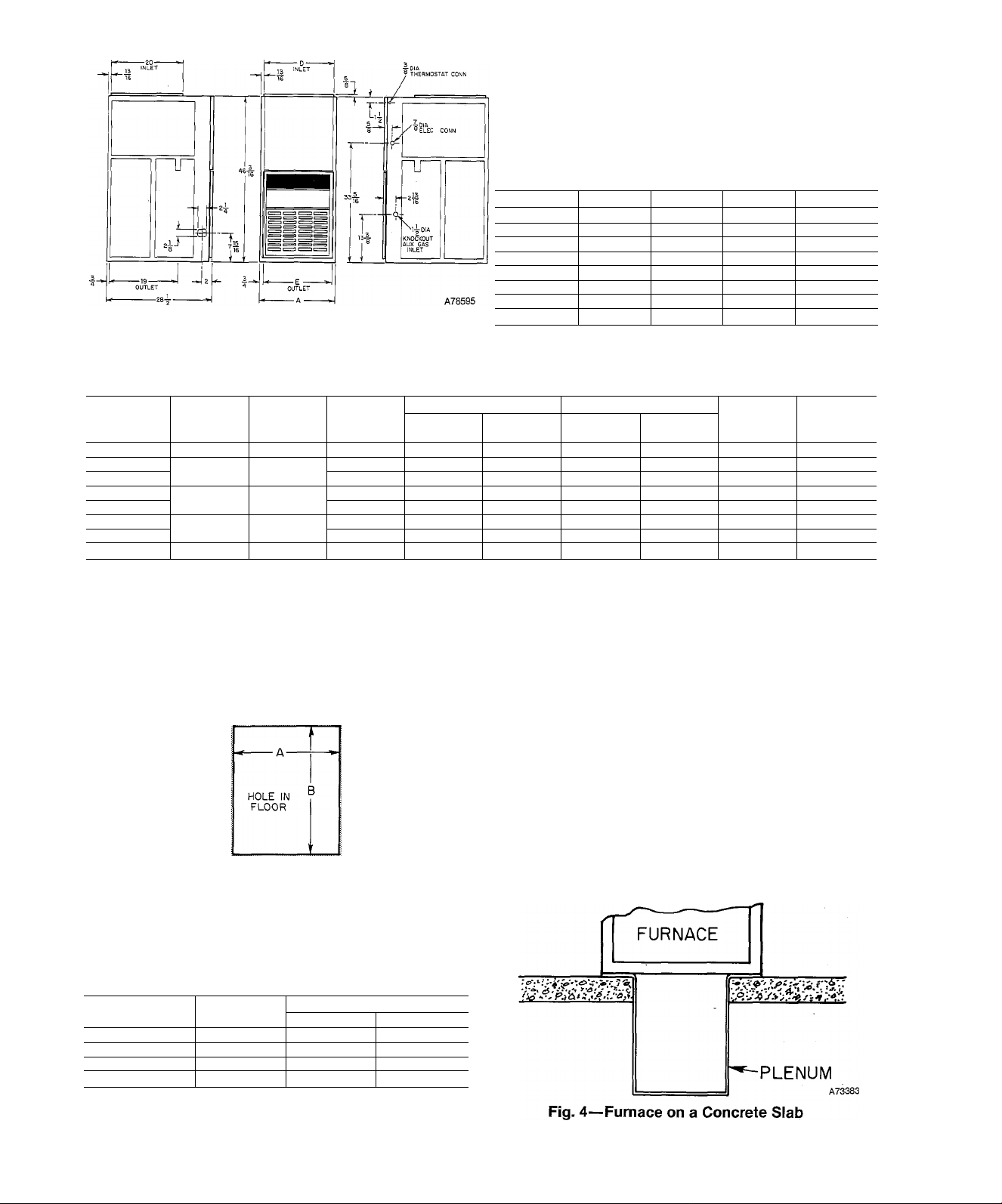
Table 2—Dimensions (in Inches)
Size Vent
050-BA
075-AA
075-BA
100-AA 17’¿
100-BA
125-AA 21
125-BA
150-BA
14^16 12^,6
M'h
M'k
177^
21
24’¿
15%
157s
15%
15%
19%
19%
22'%s
12-’-’/i6
16 4
16 4
16 5
16
19% 5
19%
23
Fig. 2—Dimensionai Drawing
Table 3—Ratings and Performance*
Size
050-BA
075-AA
075-BA
100-AA
100-BA
125-AA
125-AA
150-BA
*The above ratings are certified for aititudes to 2000 ft. For elevators above 2000 ft, reduce ratings 4% for each 1000 ft above sea level. Refer to'
National Fuel Gas Code Table F4.
fDetermined by U.S. Government tests.
ijrDeduct 1000 Btuh for Model 58DR.
Input
Btuh
50,000 39,000f
75,000 58,000
100,000 78,000t
125,000 97,000f
150,000
Capacity
Btuht
116,000f
Temp
Rise
Range
45—75 0.50
70—100 0.12
45—75 0.50 895
70—100 0.20 850
60—90 0.50
70—100 0.20
60—90
55—85 0.50 1535
Ext Static
Pressure
0.50
Heating
CFM
Ext Static
600 0.5 800 %-SP
630
960 0.5 1630 %-PSC
1050
1195 0.5 1620 'k-PSC 187
Cooling Motor
Pressure
— —
0.5 1255 %-SP 157
— —
0.5 2075 %-PSC
CFM
—
HP&
Type
7io-SP
%-SP
'h-SP
2. Construct hole in floor per dimensions in Fig. 3 and
Table 4.
3. Place plenum and furnace as shown in Fig. 4.
B. Installation on a combustible floor
1. Read Installation Instructions packaged with acces
sory combustible floor base.
2. Cut and frame hole in floor per dimensions hsted in
Installation Instructions packaged with combustible
floor base. If this requires cutting of a floor joist, tie
ends of cut joist into adjacent joists so that proper
floor support win be maintained.
3. Assemble and install combustible floor base per
instructions packaged with base.
4. When completed, combustible floor base, plenum, and
furnace (or coü casing when used) should be installed as
shown in Fig. 6.
A73382
4
5
5
6
Approx
Shipping
Weight
129
148
163
170
187
227
Fig. 3—Floor Opening for
Concrete Slab
Table 4—Opening Dimensions
Furnace Casing
Width
14%6
17%
21
24%
♦These dimensions apply when a Model 28RC or RD Evaporator Coil
casing is to be installed.
A B
13% 19%
16%6
19% 19%
23%6
Heat-Only Heat/Cool*
19%
19%
19%6
19%s
19%6
19%6
—2—
Page 3
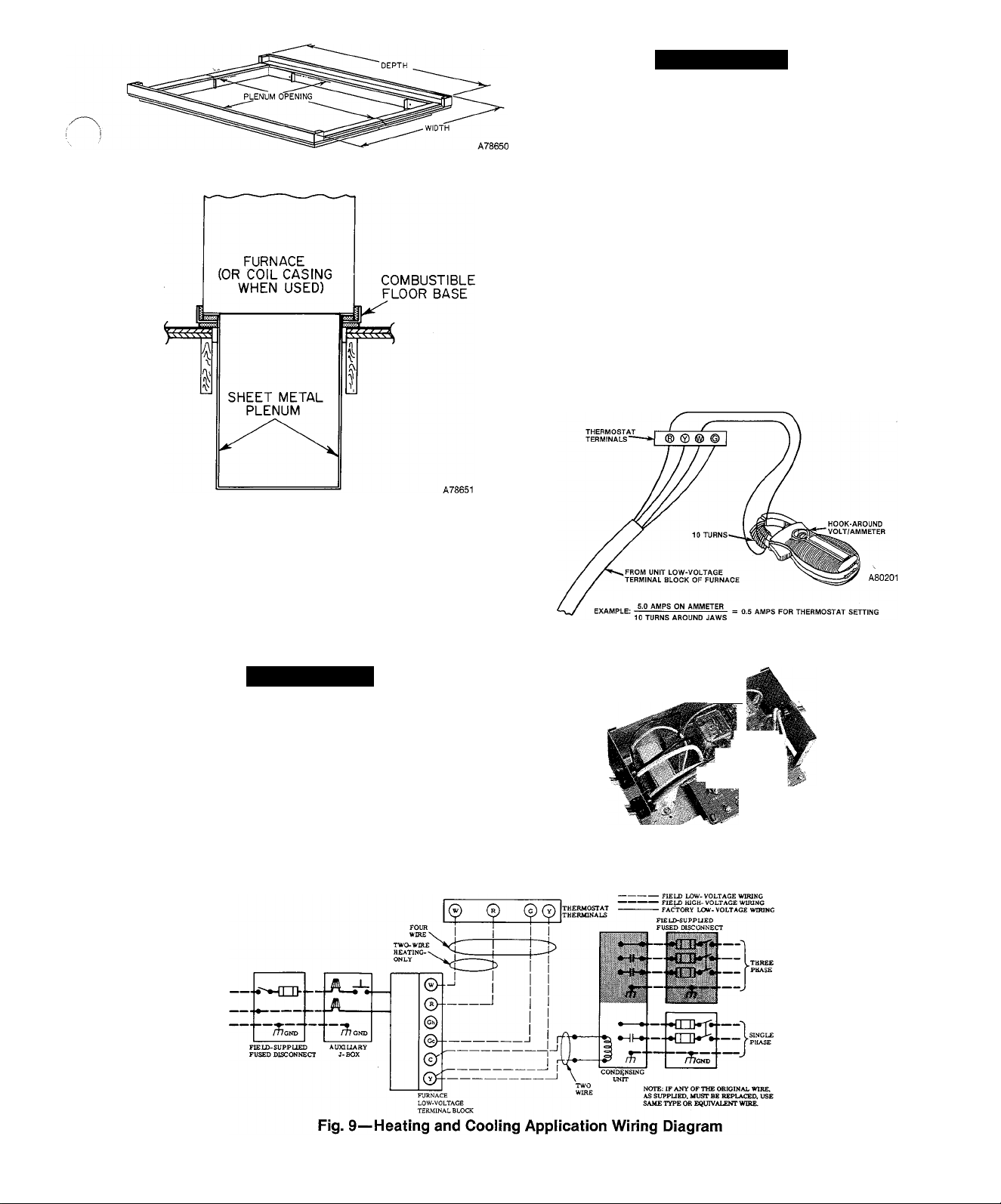
Fig. 5—Combustible Floor Base
A WARNING
The cabinet must have an uninterrupted or unbroken
ground according to National Electrical Code, ANSI/
NFPA 70-1987, or local codes to minimize personal
injury if an electrical fault should occur. This may con
sist of electrical wire or conduit approved for electrical
ground when installed in accordance with existing elec
trical codes. Do not use gas piping as an electrical
ground. A failure to adhere to this warning can result in
an electrical shock, fire, or death.
If line-voltage wiring to the unit is encased in a nonmetallic
sheath, connect the incoming ground wire to the grounding
wire inside the furnace J-box. If metallic conduit is used, it
will serve as the ground.
B. Low-Voltage Wiring
Make field low-voltage connections at the low-voltage termi
nal strip. See Fig. 9.
NOTE: Use AWG No. 18 “color-coded” copper thermostat
wire for lengths up to 100 ft. Above 100 ft, use AWG No. 16
wire.
Fig. 6—Furnace, Plenum, and
Base Installed on a Combustible Floor
VI. ELECTRICAL CONNECTIONS
A. Line-Voltage Wiring
NOTE: Refer to “Procedures for Natural-Draft Gas Fur
naces” (packaged with the equipment) for additional
information.
A CAUTION
Do not connect aluminum wire between disconnect
switch and furnace.
See Fig. 9 for wiring diagram showing the proper field high-
and low-voltage wiring.
Use a separate fused branch electrical circuit containing a
properly sized fuse or HACR-type circuit breaker for this
furnace. A disconnecting means must be located within
sight from, and readily accessible to, the furnace. In some
areas, the unit door switch may qualify as the disconnecting
means.
Fig. 7—Amp Draw Check With Ammeter
mSm
A79077
Fig, 8—Printed-Circuit Control Center
—3—
A78461.
Page 4
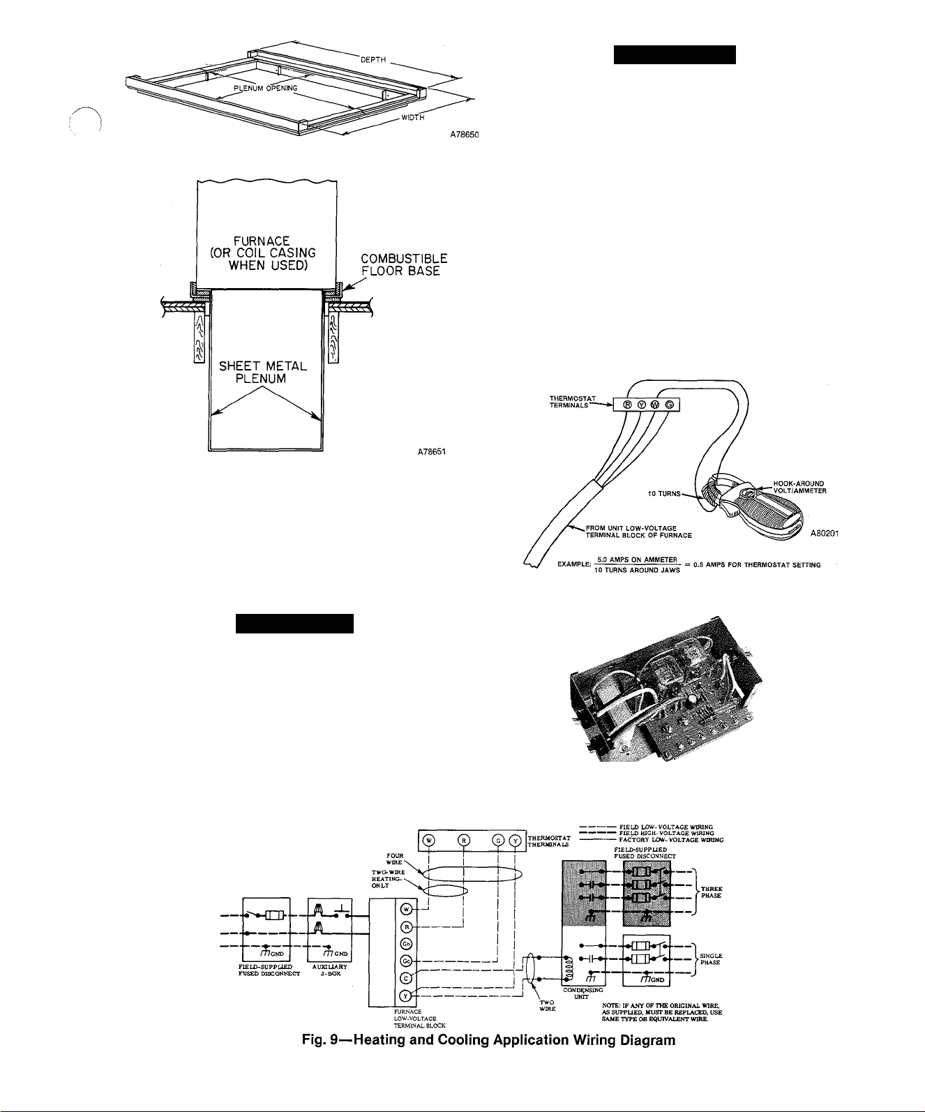
Fig. 5—Combustibie Floor Base
A WARNING
The cabinet must have an uninterrupted or unbroken
ground according to National Electrical Code, ANSI/
NFPA 70-1987, or local codes to minirnize personal
injury if an electrical fault should occur. This may con
sist of electrical wire or conduit approved for electrical
ground when installed in accordance with existing elec
trical codes. Do not use gas piping as an electrical
ground. A failure to adhere to this warning can result in
an electrical shock, fire, or death.
If line-voltage wiring to the unit is encased in a nonmetaUic
sheath, connect the incoming ground wire to the grounding
wire inside the furnace J-box. If metallic conduit is used, it
will serve as the ground.
B. Low-Voltage Wiring
Make field low-voltage connections at the low-voltage termi
nal strip. See Fig. 9.
NOTE; Use AWG No. 18 “color-coded” copper thermostat
wire for lengths up to 100 ft. Above 100 ft, use AWG No. 16
wire.
Fig. 6—Furnace, Plenum, and
Base Installed on a Combustible Floor
VI. ELECTRICAL CONNECTIONS
A. Line-Voltage Wiring
NOTE; Refer to “Procedures for Natural-Draft Gas Fur
naces” (packaged with the equipment) for additional
information.
A CAUTION
Do not connect aluminum wire between disconnect
switch and furnace.
See Fig. 9 for wiring diagram showing the proper field highand low-voltage wiring.
Use a separate fused branch electrical circuit containing a
properly sized fuse or HACR-t5q)e circuit breaker for this
furnace. A disconnecting means must be located within
sight from, and readily accessible to, the furnace. In some
areas, the unit door switch may qualify as the disconnecting
means.
Fig. 7—Amp Draw Check With Ammeter
A79077
Fig. 8—PrInted-CIrcult Control Center
—3-
A78461.
Page 5
TRAN
FUSED DISCONNECT SWITCH
SWITCH (WHEN REQ'D) /
FU2
PR1
GRN ^ CRNGRN
AUX. J-BOX
COM.
HIGH
MED HIGH
BRN
BRN
GAP
(WHEN USED)
BREAKAWAY TAB REMOVED WHEN CONNECTING VENT DAMPER (SEE INSTALLATION INSTRUCTIONS)
NOTES:
* DOWNFLOW FURNACES ONLY
1- I--rm HEATING FAN RELAY OONTACT IS
' HFR APPLIED TO FURNACE.
2. TO CHANGE MOTOR SPEED, MOVE RED WIRE TO
DESIRED SPEED SETTING.
3. IF ANY OF ORIGINAL WIRE AS SUPPLIED WITH
THE APPLIANCE MUST BE REPLACED, IT MUST
BE REPLACED WITH AWM (105°C) WIRE OR ITS
EQUIVALENT.
4. MOTOR IS THERMALLY OVERLOAD’PROTECTED.
5. FACTORY SPEED SELECTION IS FOR AVERAGE
CONDITIONS, SEE INSTALLATION INSTRUCTIONS
FOR OPTIMUM SPEED SELECTION. MOTOR MAY
BE 3 OR 4 SPEED.
6. SYMBOLS ARE ELECT. REPRESENTATION ONLY.
7. FACTORY CONNECTED WHEN ACCESSORY NOT USED.
LEGEND
AL3 AUXILIARY LIMIT SWITCH, MANUAL-RESET
CAP RUN CAPACITOR
CFR COOLING FAN RELAY CDPDT
FL FUSIBLE LINK
FU1 FUSE IN LINE 2 AMP
FU2 FIELD FUSE
GV GAS VALVE
HFR HEATING FAN RELAY (SPST-NC)
ILK SWITCH^ BLOW. DOOR INTERLOCK (SPST-NO)
LOD LOCKOUt TIMER DEVICE (SPST-NO)
LS LIMIT SWITCH^ AUTO.-RESET (SPST-NC)
MTR MOTOR, BLOWER
PCB PRINTED CIRCUIT BOARD
PI PILOT IGNITER
SP SAFETY PILOT (FLAME SENSING)
TRAN TRANSFORMER
VSSS VENT SAFETY SHUTOFF SWITCH, MANUAL-
FIELD SPLICE
PLUG RECEPTACLE
JUNCTION
UNMARKED TERMINAL
— TERMINAL PCB FACTORY CONN.
------- FACTORY WIRING (120V AC)
------- FACTORY WIRING (LOW VOLTAGE)
---- FIELD WIRING (120V AC)
------
FIELD WIRING (24V AC)
== CONDUCTOR ON PRINTED CIRCUIT BOARD
MED LOW
LOW
MTR
NORMALLY CLOSED UNTIL 115V AC IS
(SPST-NC)
RESET (SPST-NC)
BLK
WHT
WHT
BLK
RED
C Y Gr 6h/ V R W
0 0 0 0 0 0
BLK
WHT
CFR
TO THERMOSTAT
ILK
LINE
4
HFR
HFR CFR
(WHEN USED)
RED
BLU RED
1 r
SEC-2 SEC-1
LIM-2 LIM-1
GAS-2
GAS-3 GAS-1
LIM-1 SEC-1 FU1
-1^ k-
0 SCREW TERMINAL FOR FIELD WIRING
FIELD GROUND
/-fy EQUIP. GROUND
SEE NOTE
*7
YEL
LOD-
(WHEN USED)
ELECTRONIC
AIR CLEANER
(WHEN USED)
EAC-1
120V AC
t' 't
19 7|
-1
i !
1
1
t T
Ttt
310586-402 REV. C
EAC-2
___
PI i
LINE-2
CAP
I
SEC-2
BRN
COM.
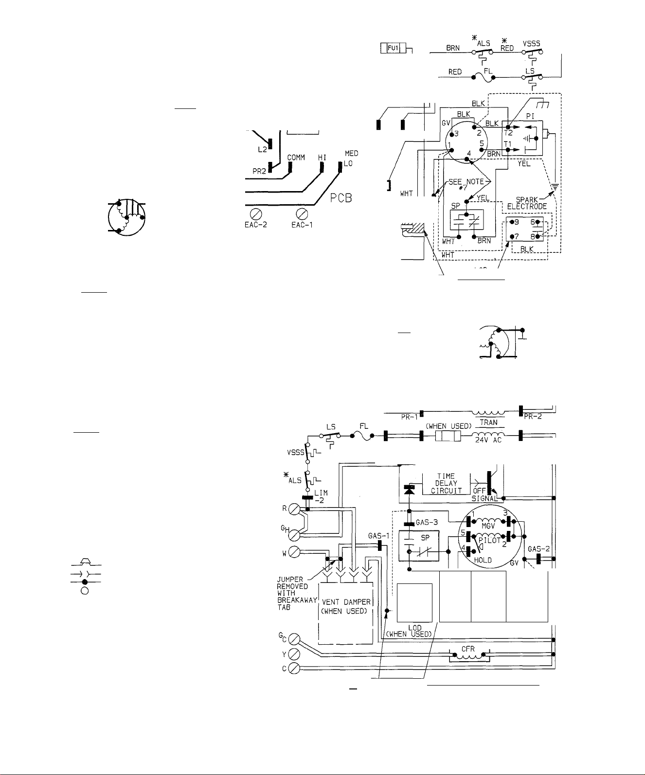
Fig. 10—Wiring Diagram (liD Piiot)
-4-
A87405
Page 6
FUSED DISCONNECT
SWITCH CWHEN REQ'D)
ILK SWITCH
BLK
TRAN CWHEN USEDD
BRN
CAP
CWHEN USED)
NOTES:
*
DOWNFLOW FURNACES ONLY
1 .
HFR ■ APPLIED TO FURNACE.
2.
TO CHANGE MOTOR SPEED, MOVE BLK OR RED
WIRE TO DESIRED SPEED SETTING.
IF ANY OF ORIGINAL WIRE AS SUPPLIED WITH
3.
THE APPLIANCE MUST BE REPLACED, IT MUST
BE REPLACED WITH AWM C105”C) WIRE OR ITS
EQUIVALENT.
MOTOR IS THERMALLY OVERLOAD PROTECTED.
4.
5.
FACTORY SPEED SELECTION IS FOR AVERAGE
CONDITIONS, SEE INSTALLATION INSTRUCTIONS
FOR OPTIMUM SPEED SELECTION. MOTOR MAY
BE 3 OR 4 SPEED.
6.
SYMBOLS ARE AN ELECTRICAL REPRESENTATION ONLY.
LEGEND
ALS AUXILIARY LIMIT SWITCH, MANUAL-RESET
CAP RUN CAPACITOR
CFR COOLING FAN RELAY (DPDT)
FL FUSIBLE LINK
FUl FUSE IN LINE 2 AMP
FU2 FIELD FUSE
6V GAS VALVE
HFR HEATING FAN RELAY CSPST-NC)
ILK SWITCH, BLOWER DOOR INTERLOCK CSPST-NO)
LS LIMIT SWITCH, AUTOMATIC-RESET CSPST-NC)
MTR MOTOR, BLOWER
PCB PRINTED CIRCUIT BOARD
TRAN TRANSFORMER
VSSS VENT SAFETY SHUTOFF SWITCH, MANUAL-RESET
— TERMINAL PCB FACTORY CONN.
----
----
---== CONDUCTOR ON PRINTED CIRCUIT BOARD
HEATING FAN RELAY CONTACT IS
NORMALLY CLOSED UNTIL 115V AC
CSPST-NC)
CSPST-NC)
FIELD SPLICE
PLUG RECEPTACLE
JUNCTION
MARKED TERMINAL
UNMARKED TERMINAL
FACTORY WIRING Cl 20V AC)
FACTORY WIRING CLOW VOLTAGE)
FIELD WIRING C120V AC)
IS
0 SCREW TERMINAL FOR FIELD WIRING
^ FIELD GROUND
ffj EQUIP. GROUND
TO THERMOSTAT
JUMPER
REMOVED r
WITH
BREAKAWAY
TAB
^0
C0
HFR CFR
LIM-1 SEC-1 FUI
.0YY
VENT DAMPER
CWHEN USED)
ELECTRONIC
AIR CLEANER
CWHEN USED)
%r
PR-1
CWHEN USED) TRAN
K
TIME
DELAY
CIRCUIT
GAS-3
310471-402 REV. B
3
SIGNALht
BREAKAWAY TAB
REMOVED WHEN
CONNECTING VENT
DAMPER CSEE
INSTALLATION
INSTRUCTIONS)
LI
NE-2 ^
CAP
1
;)
T
COM.
---
.
r?\
----------
^EAC-2
AC ■
■PR-2
■SEC-2
.
GAS-2
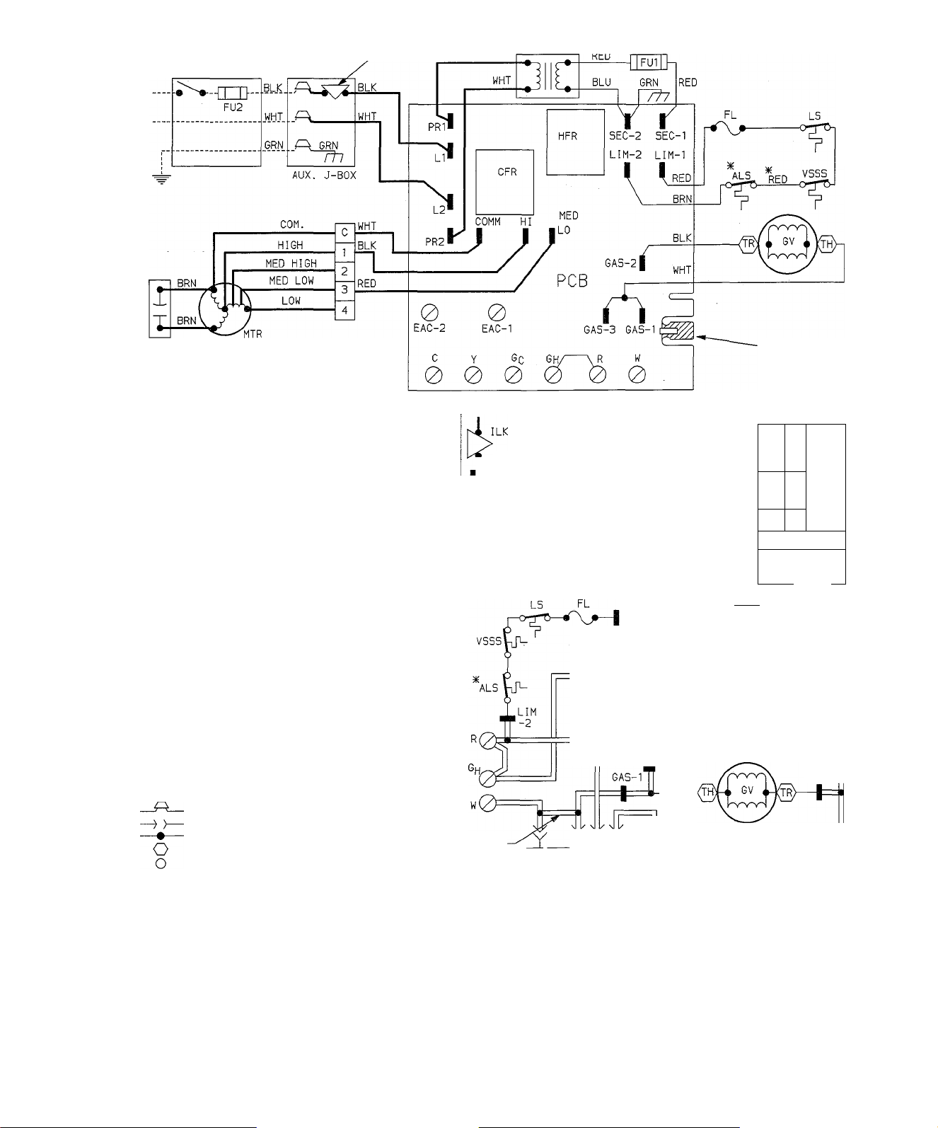
Fig. 11—Wiring Diagram (Match-iit Piiot)
—5—
A87406
Page 7

IMPORTANT: The thermostat heat anticipation must be set
to match the amp draw of the gas valve and electrical com
ponents in the R-W circuit. Accurate amp draw readings
can be obtained at thermostat subbase terminals R & W.
Fig. 7 illustrates an easy method for obtaining the actual
amp draw.
The room thermostat should be located where it wiU be in
the natural circulation path of room air. Avoid locations
where the thermostat would be exposed to cold-air infiltra
tion, drafts from windows, doors, or other openings leading
to the outside, or exposure to air currents from warm- or
cold-air registers; or to exposure where the natural circula
tion of the air is cut off—such as behind doors, above or
below mantels, shelves, etc.
The thermostat should not be exposed to heat from nearby
fireplaces, radios, televisions, lamps, or rays from the sun.
Nor should the thermostat be mounted on a wall containing
pipes or warm-air ducts, or a flue or vent that could affect
its operation and prevent it from properly controlling the
room temperature. Any hole in the plaster or panel through
which the wires pass from the thermostat should be ade
quately sealed with suitable material to prevent drafts from
affecting the therniostat.
C. Blower Control Center
Each furnace features a printed-circuit control center. This
will aid the installer and serviceman when installing and
servicing the unit. See Fig. 8. A low-voltage terminal board
is marked for easy connection of field wiring.
VII. SEQUENCE OF OPERATION
NOTE: The wiring diagrams shown in Figs. 10 and 11 cover
heating/coohng units.
A. Heating
Gas and electrical supplies must be turned on at the
furnace.
NOTE: When power is apphed to heat relay cofl. HFR in the
control circuit, the normally closed contacts in the blower
circuit will open.
1. White Rodgers 36E Gas Valve piD Models). See Fig. 10.
When the thermostat “calls for heat,” the control circuit is
closed between terminals R and W. Power from transformer
TRAN through fusible link FL, hmit switches LS & ALS
and vent safety shut-off switch VSSS, energizes the pilot
valve part of automatic gas valve GV and pilot igniter PI.
The pilot valve opens, permitting gas flow to the pilot
burner where it is ignited.
The pilot valve portion of automatic gas valve GV has a
“pick” solenoid coil and latching “hold” device. The “pick”
coU must be energized to open the pilot valve, but only the
“hold” device must be energized to keep it open.
The “hold” device varies with the gas valve design used on
the furnace. It could be an internal pressure switch in series
with the “pick” solenoid coil, an raternsil electrical resistor
in series with the solenoid “pick” coil, or a separate electriceil solenoid coU.
When the pilot flame is estabhshed, safety pilot SP switches
its contacts in approximately 40 to 60 seconds, energizing
the main valve portion of gas valve GV and deenergizing
safety pilot igniter SP and the “pick” coil of the pilot sole
noid portion in gas valve GV. The pilot valve is held open by
the “hold” device within gas valve GV.
The main valve portion of gas valve GV has a delayed open
ing operator that opens within 6 to 15 seconds after it is
energized, permitting gas flow to the main burners where
the gas is ignited by pilot SP.
2. Honeywell VR 800A Gas Valve (Match-Lit Models). See Fig. 11
The furnace pilot must be ht to energize the thermal magnet
circuit of gas valve GV, thus permitting gas flow to the
remaining portion of the valve.
When the thermostat “calls for heat,” the control circuit is
closed between terminals R and W. Power from transformer
TRAN through fusible linkn FL, limit switch LS & ALS and
vent safety shutoff switch VSSS energizes gas valve GV,
causing the valve to open and permitting gas flow to the
main burners, where it is ignited by the pilot.
3. Blower Circuit
With power through the solid-state time-delay circuit on
printed-circuit board PCB and heat relay HFR, blower
motor MTR is energized on heating speed approximately 75
seconds after gas valve GV has been energized (or the pilot
flame has been proven in the case of IID systems).
4. Limit Control
If the furnace overheats for any reason, hmit control LS
switches, breaking the circuit to automatic gas valve GV.
The gas valve closes immediately, stopping gas flow to the
main burners and the pilot. In addition, Iplower motor MTR
continues to operate because heat relay HFR is deenergized
to cool down the furnace.
Manual reset auxffiary limit switch ALS is located on the
top right-hand corner of the furnace. In the event of blower
motor failure, this switch breaks the electrical circuit to the
gas valve, stopping gas flow to the main burners. The
switch must be manuahy reset after the blower motor has
been replace.
Fusible link FL is provided in the transformer TRAN sec
ondary circuit as protection from overheating conditions in
the vestibule area of the furnace. Should this condition
exist, the fuse opens and deenergizes gas valve GV and heat
relay HFR, stopping the gas flow to the burners and start
ing blower motor MTR.
When the thermostat is satisfied, the circuit between R and
W is broken, deenergizing automatic gas valve GV, pilot SP
(when used), and the solid-state time-delay circuit on
printed-circuit board. The gas flow stops immediately to the
pilot and main burners with the IID controls, and to the
main burners only with standing pilot controls. After
approximately 105 seconds, heat relay HFR is energized
and blower motor MTR stops.
5. Vent Safety Shut-off System Switch
The purpose of this control is to safely shutdown the fur
nace if a blocked vent condition occurs.
During a blocked vent condition, temperature in the
drafthood opening will rise causing vent safety shut-off
switch to open, breaking the circuit to gas valve GV. The
gas valve closes immediately, stopping gas flow to the main
burners and pilot, and the blower will run continuously.
The furnace will remain in this mode until the vent safety
shut-off system switch is manually reset.
B. Vent Damper (When Used)
With gas and electrical power supphed to the furnace, the
vent damper motor is deenergized, and the vent damper is
closed until the thermostat “calls for heat.”
On a “call for heat” by the thermostat, the vent damper
motor is energized and the damper opens. When the vent
damper reaches the full-open position, the damper motor is
deenergized and a circuit is completed to the main gas valve
via the pilot. At this time, the main gas valve is energized
and the main burners are ignited; the vent damper will
—6—
Page 8
remain open until the thermostat is satisfied.
When the thermostat is satisfied, it will deenergize the main
gas valve and stop the gas flow. The vent damper motor will
energize and close the damper. When the vent damper
reaches the full-closed position, the damper motor is
deenergized and will remain so until the next “call for heat”
by the thermostat.
C. Cooling (Cooling Models Only)
When the thermostat “calls for cooHng,” power from trans
former TRAN energizes the condensing unit contactor, cool
ing relay coil CFR, closing its contacts and energizing
blower motor MTR on its cooling speed. It continues to
operate until the thermostat is satisfied.
When the thermostat is satisfied, the circuit to terminal Gc
is broken, deenergizing cooling relay coil CFR which, in
turn, opens its contacts, stopping blower motor MTR.
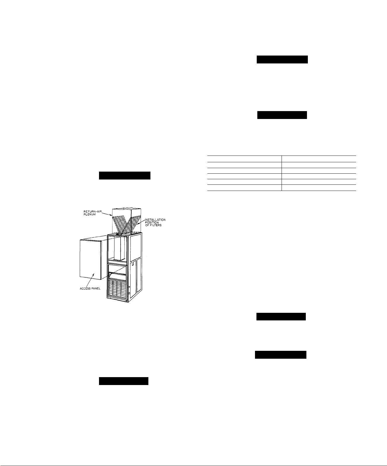
VIII. FILTER ARRANGEMENT
The two factory-supplied filters are shipped in the blower
compartment. After the return-air duct has been connected
to the furnace, install the filters in a V-formation inside the
retum-air plenum. See Fig. 12.
A
WARNING
Never operate the unit without a filter or with the filter
access door removed. A failure to adhere to this warn
ing can cause a fire, physical injury, or death.
NOTE: The gas valve regulator has been nominally-set at
3.5 in. wc for natural gas. Refer to “Procedures for NaturalDraft Gas Furnace Installation” for readjusting when
checking input.
A. Adjustment of Blower Speed
A WARNING
Disconnect the electrical power before changing the
speed tap. A failure to adhere to this warning can cause
personal injury.
To change motor speed taps, remove the motor tap lead (See
Table 5.) and relocate it on the desired terminal on the plug
in terminal block/speed selector located on the blower.
A CAUTION
When adjusting the blower speed, make certain that
the temperature rise across the heat exchanger does not
exceed that specified on the rating plate.
Table 5—Speed Selector
Speed
Common C
Hi
Med-Hi 2
Med-Low 3
Low 4
♦Furnaces without a cooling fan relay are equipped with a 3-speed
motor.
fWhite wire from control box to common; black wire from control box
to cooling speed selection (when used); red wire from control box to
heating speed selection.
Tap No.*t
1
A78654
Fig. 12—Position of Filters
IX. STARTUP AND ADJUSTMENT
In addition to the following information, refer to “Proce
dures for Natural-Draft Gas-Fired Furnaces” packaged with
the unit.
NOTE: There is a switch located in the blower compartment
that breaks the electrical power supply when the blower
access door is removed. Be sure the blower access door is
properly installed.
A
CAUTION
This furnace is equipped with a fusible link in the vesti
bule area that wQl melt if an overheating condition
caused by an inadequate combustion-air supply or
improper venting practices develops. Do not jumper
this fuse. Correct the condition and replace the fuse
with an identical part.
The gas service pressure must not exceed 0.5 psig (14
in. wc).
B. Automatic Gas Control Valve
These units are equipped with an automatic gas control
valve. If not already checked when lighting the main
burner, check the proper operation of this valve by moving
the room thermostat pointer above and below room temper
ature and observing that the meiin burners light on “call for
heat” and go off when the pointer is moved below room tem
perature setting.
NOTE: For ease of adjusting the pilot flame, disconnect ter
minal No. 1 at the gas valve. This will prevent main burner
ignition and allow time to adjust the pilot. Reconnect the
power lead after adjustment.
X. CARE AND MAINTENANCE
A CAUTION
Because of possible damage to the equipment or per
sonal- injury, maintenance should be performed by qual
ified persons only.
A WARNING
Never store anything on, or in contact with, the fur
nace, such as:
1. Spray or aerosol cans, rags, brooms, dust mops,
vacuum cleaners, or other cleaning tools.
2. Soap powders, bleaches, weixes or other cleaning
compounds, plastic or plastic containers, gasoline,
kerosene, cigarette lighter fluid, dry cleaning fluids,
or other volatile fluids.
3. Paint thinners and other painting compounds,
paper bags or other paper products.
A failure to adhere to this warning can cause corrosion
of the heat exchanger and vent system, fire, personal
injmy, or death.
-7—
Page 9
MANUAL ON/OFF
X
ULATOR
USTMENT
m'
MANUALON/OFF
REGULATOR
ADJUSTMENT
m
'rm
í/
A78568
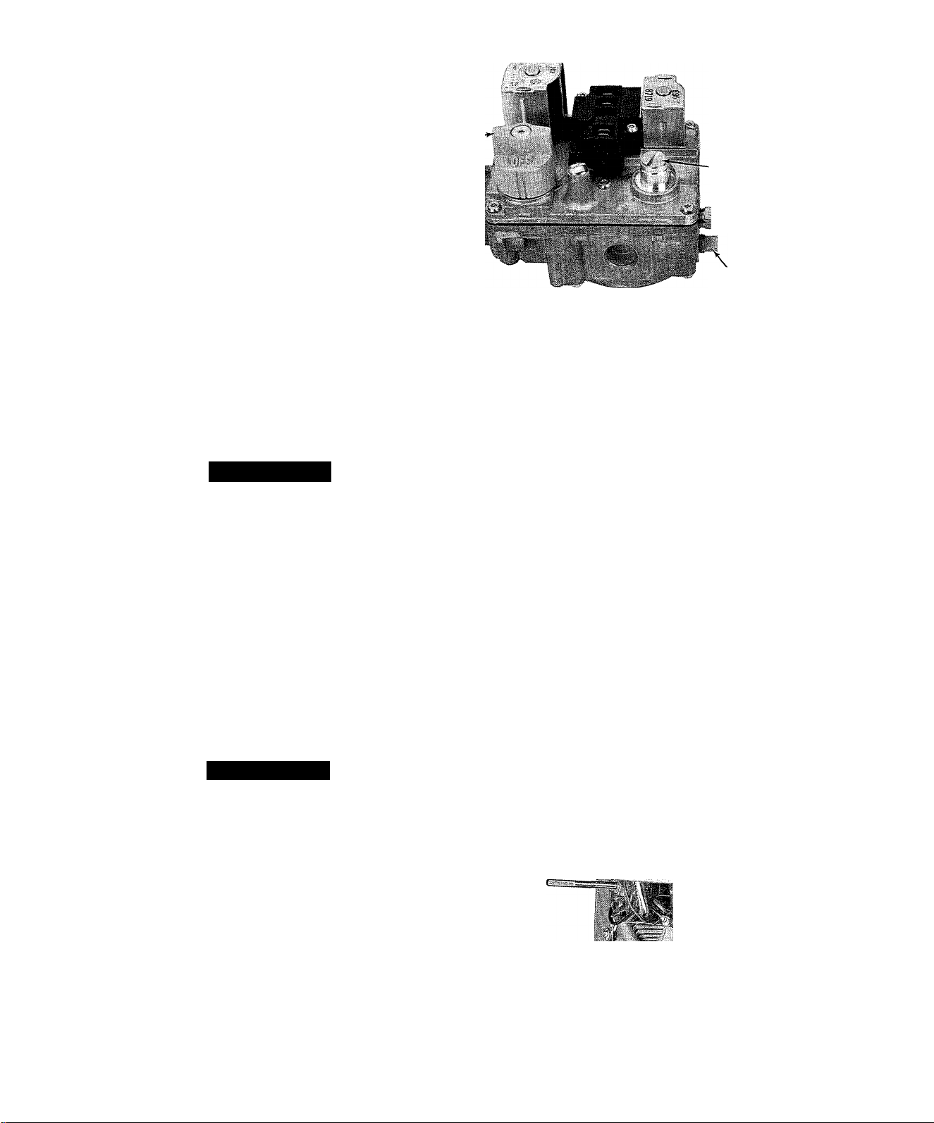
Fig. 13—Honeywell Model VR 800A
For continuing high performance, and to niinhnize possible
equipment failure, it is essential that periodic maintenance
be performed on this equipment. Consult your local Dealer
as to the proper frequency of maintenance and the availabil
ity of a maintenance contract.
The abihty to properly perform maintenance on this equip
ment requires certain mechanical skills and tools. If you do
not possess these, contact your Dealer for maintenance.
A
WARNING
Turn off the gas and electrical supplies to the unit
before performing any medntenance or service it. FoUow
the rehghting instructions on the label attached to the
furnace. A failure to adhere to this warning can cause
personal injury.
The minimum maintenance that should be performed on the
equipment is as follows:
1. Check and clean or replace air filter each month or as
required.
2. Check blower motor and wheel for cleanliness and lubri
cation each heating and cooUng season. Clean and
lubricate as necessary.
3. Check electrical connections for tightness and controls
for proper operation each heating season. Service as
necessary.
A WARNING
PILOT TUBE
CONNECTOR
MANIFOLD
PRESSURE TAP A87230
Fig. 14—White Rodgers Model 36E
4. Some furnaces are equipped with permanent, washable
filters. Clean those filters as follows:
a. Clean with tap water.
b. Rinse and let dry. No oiling or coating of filters is
required.
c. Reinstall filters with cross-hatch binding facing
blower.
B. Blower Motor Wheel
Clean and lubricate as follows:
1. Remove upper access panel.
2. Loosen screw in vent pipe enclosure front and remove
vent enclosure front by sliding forward (toward front of
unit).
3. Disconnect vent pipe at first joint above unit and
swing vent pipe assembly to side, supported by suit
able means (block of wood, etc.).
4. Shde vent pipe upward through rectangular opening in
top plate and remove vent pipe from furnace.
5. Remove four screws in vent pipe enclosure back, and
remove enclosure back by tilting top toward blower
and sliding bottom toward front of furnace.
6. Disconnect electrical leads from right side of motor
speed selector. Note location of wires for reassembly.
7. Remove screws holding blower assembly against
blower deck and shde blower assembly out of furnace.
8. Squeeze side tabs of motor speed selector and puU it
from blower housing.
As with any mechanical equipment, personal injury can
result from sharp metal edges, etc.; therefore, be careful
when removing parts.
A. Air Filter
Each furnace accommodates two filters which can be
installed above the furnace in the return-air plenum. See
Fig. 12.
To clean or replace the filters, proceed as follows:
1. Disconnect electrical power before removing access
panel.
2. Remove upper access panel.
3. Reach up behind top plate, tilt filters toward center of
retum-air plenum, remove filters, and replace or clean
as needed.
V 4,
A77007
Fig. 15—Dual Blower With Left-Hand
Housing and Wheel Removed
—8—
Page 10
9. Units with motor capacitor, loosen screw in strap hold
ing capacitor to blower housing and slide capacitor
from under strap.
10. Mark blower wheel, motor, and motor support in rela
tion to blower housing before disassembly, to insure
proper reassembly.
11. Loosen setscrew holding blower wheel onto motor
shaft.
12. Remove bolts holding motor mount to blower housing
and slide motor and mount out of housing. Some
motors have a ground wire attached to blower housing;
disconnect it also.
13. Lubricate motor.
a. Remove dust caps or plugs from oU ports located at
each end of motor.
b. Use good grade of SAE 20 nondetergent motor oU
and put one teaspoon, 5cc, 3/16 oz., or 16 to 25
drops in each oil port.
c. Allow tune for total quantity of oil to be absorbed
by each bearing.
d. After oiling motor, be sure to wipe excess oil from
motor housing.
e. Replace dust caps or plugs on oil ports.
14. Remove blower wheel from housing.
a. Mark blower wheel orientation and cutoff location
to insure proper reassembly.
b. Remove screws holding cutoff plate and remove cut
off plate from housing.
c. Lift blower wheel from housing through opening.
15. Clean blower wheel and motor by using vacuum with
soft brush attachment. Care must be exercised not to
disturb balance weights (clips) on blower wheel vanes.
Also do not drop or bend wheel, as balance will be
affected.
16. Reassemble blower by reversing procedures 14a thru
14c. Be sure wheel is positioned for proper rotation.
17. Reassemble motor and blower by reversing procedures
8 thru 12. If motor has ground wire, be sure it is con
nected as before. Be sure the blower wheel setscrew is
on the flat of the motor shaft when tightening the
setscrew.
18. Reinstall blower assembly in furnace.
19. Reinstall vent enclosure back.
20. Reinstall vent pipe through opening in top plate, secure
to drafthood and connect remainder of vent pipe
assembly.
21. Reinstall vent enclosure front, and secure with screw.
22. Reinstall access panel.
C. Cleaning Heat Exchanger
If it becomes necessary to clean the heat exchanger because
of carbon deposits, soot, etc., proceed as follows:
1. Turn off gas and electrical supply to furnace.
2. Remove front access doors.
3. Remove vent pipe enclosure front and flue pipe.
4. Remove draft diverter. Screws are located inside draft
diverter opening.
5. Remove flue baffles from flue outlets of heat
exchanger.
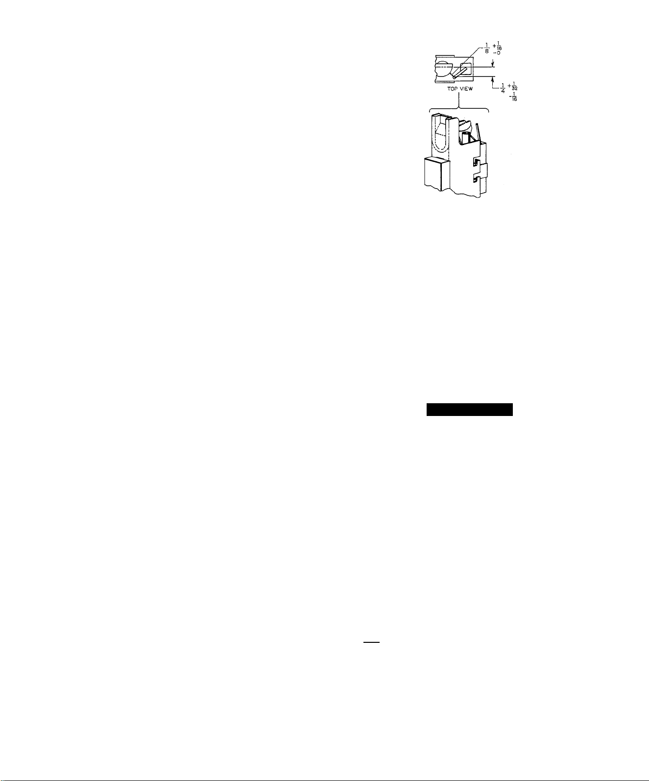
A79080
Fig. 16—Position of Electrode to Pilot
6. Remove secondary-air shield and burners. To remove
pilot burner, disconnect pilot supply tube (and thermo
couple on 100% shut-off models) at gas valve.
7. Clean flue ways writh brush and or vacuum. Check heat
exchanger for leaks and cracks. Replace if necessary.
8. Replace flue baffles. Be sure aU screws are in place emd
tight.
9. Replace draft diverter and vent connector. Be sure
screws are replaced and tight.
10. Using vacuum cleaner wdth soft brush attachment,
clean burners. After cleaning, replace burners and
secondary-air shield.
11. Turn on gas and electricity. Check for gas leaks.
A WARNING
Never use a match or other open flame to check for gas
leaks. Use a soap-and-water solution. A failure to
adhere to this warning can cause an explosion, fire, per
sonal injury, or death.
D. Pilot
Check the pilot and clean if necessary at the beginning of
each heating season. The pilot flame should be high enough
for proper inipingement of the safety element and to light
the burners. Remove the accvunulation of soot and carbon
from the thermocouple safety element or sensing probe.
E. Electrical Controls and Wiring
NOTE: There may be more them one electrical supply to
unit.
With power disconnected to unit, check aU electrical connec
tions for tightness. Tighten any screws or electrical connec
tions. If any smoky or burned connections are noticed, dis
assemble the connection, clean all parts, and stripped wore,
and reassemble properly and securely. Electrical controls
are difficult to check without proper instrumentation; there
fore, reconnect electrical power to unit and observe unit
through one complete operating cycle. If there are any dis
crepancies in the operating cycle, contact your Dealer and
request service.
-9—
 Loading...