

Page 1
52C and 52P
52C
SERIES
SERIES
OWNER’S MANUAL
PACKAGED TERMINAL AIR CONDITIONERS
AND HEAT PUMPS
7,000-15,000 Btuh
CONTENTS
Page
GENERAL. . . . . . . . . . . . . . . . . . . . . . . . . . . . . . . . . . . . . . . 2
UNIT INSPECTION. . . . . . . . . . . . . . . . . . . . . . . . . . . . .2,3
FRONT PANEL . . . . . . . . . . . . . . . . . . . . . . . . . . . . . . . . 2
ELECTRICAL DATA. . . . . . . . . . . . . . . . . . . . . . . . . . . . . . 4
ALL UNITS. . . . . . . . . . . . . . . . . . . . . . . . . . . . . . . . . . . . 4
VOLTAGE SUPPLY . . . . . . . . . . . . . . . . . . . . . . . . . . . . . 4
INSTALLATION . . . . . . . . . . . . . . . . . . . . . . . . . . . . . . . .5-8
CHASSIS INSTALLATION . . . . . . . . . . . . . . . . . . . . . . 5
WA LL THERMOSTAT INSTALLATION. . . . . . . . . . . 8
OPERATION . . . . . . . . . . . . . . . . . . . . . . . . . . . . . . . . . .9,10
COMFORT CONTROLS. . . . . . . . . . . . . . . . . . . . . . . . . 9
OPERATING CONTROLS. . . . . . . . . . . . . . . . . . . . . . 10
OPERATING MODES. . . . . . . . . . . . . . . . . . . . . . . . . . 10
Page
CARE AND MAINTENANCE . . . . . . . . . . . . . . . . . 11,12
INDOOR-AIR INLET FILTERS . . . . . . . . . . . . . . . . . . 11
EXTERNAL PARTS . . . . . . . . . . . . . . . . . . . . . . . . . . . .12
INTERNAL PARTS . . . . . . . . . . . . . . . . . . . . . . . . . . . . 12
PREVENTATIVE MAINTENANCE. . . . . . . . . . . . . . . . 13
TROUBLESHOOTING. . . . . . . . . . . . . . . . . . . . . . . . . . . 14
ACCESSORIES. . . . . . . . . . . . . . . . . . . . . . . . . . . . . . . . . . 15
1•800•894•6449 (in USA and Canada)
For Service/Technical Assistance
1•800•830•8600 (Mexico)
Manufacturer reserves the right to discontinue, or change at any time, specifications or designs without notice and without incurring obligations.
Book 1 4
Ta b 9 a 1 1 a
PC 132 Catalog No. 535-20066 Printed in U.S.A. Form 52C,P-2SO Pg 1 10-04 Replaces: 52C,P-1SO
Page 2
GENERAL
FIGURE 1 — SAMPLE DATA INFORMATION PLATE
Thank you for choosing Carrier! You can feel confident
in your selection because the same pride in craftsmanship and engineering knowledge that goes into Carrier
equipment at the Astrodome in Texas, the Sistine
Chapel in Rome, the US Capitol Hall of Congress, and
thousands of other installations worldwide has gone
into the construction of this unit.
The Carrier package terminal air conditioners and
heat pumps provide a high standard of quality in performance, workmanship, durability and appearance as
they heat and cool the occupied air space year round.
This manual provides information for ease of installation, operation and maintenance of the 52C and 52P
units. The following units are covered in this manual
(see Figure 1 for additional unit information):
52CE 60 Hz cooling with electric heat units
52CQ 60 Hz cooling, electric heat, and heat pump units
52PE 60 Hz cooling with electric heat units
52PQ 60 Hz cooling, electric heat, and heat pump units
52PC 60 Hz cooling only units
All models are designed for through-the-wall installation. Separate installation instructions are included
MODEL 52PQA312301AA
SERIAL 3701X11520
DATE OF MFG. 09/12/2001
VOLT RANGE 187-253
VOLTS 230/208
PH 1
MIN CKT AMPACITY 19.3
R-22 OZ 34
DESIGN PSIG 350 HIGH SIDE, 150 LOW SIDE
BTU/HR 12,100/12,000
AMPS 4.8/5.3
WATTS 1100/1100
EER 11.0/10.9
COMP
FAN
MOTOR
BTU/HR 10,800/10,700
AMPS 15.6/14.5
WATTS 3570/2997
COP 3.2/3.2
HEATER
BTU/HR
USE
TIME DELAY FUSE
OR HACR TYPE
CIRCUIT BREAKER
HZ
COOLING
6.1
RLA
29
LRA
0.75
FLA
1/8
HP
HEATING
AMPS 14.8/13.7
WATTS 3400/2850
WATER
STEAM
CANADIAN INSTALLATION
AMP
20
MAX FUSE
60
AMP AMP
20
MAX BREAKER
20
with all accessory components. See Accessories section
on page 15 for complete listing of accessories.
UNIT INSPECTION
Examine unit for damage incurred during shipment.
File a claim immediately with the transit company if
damage is found.
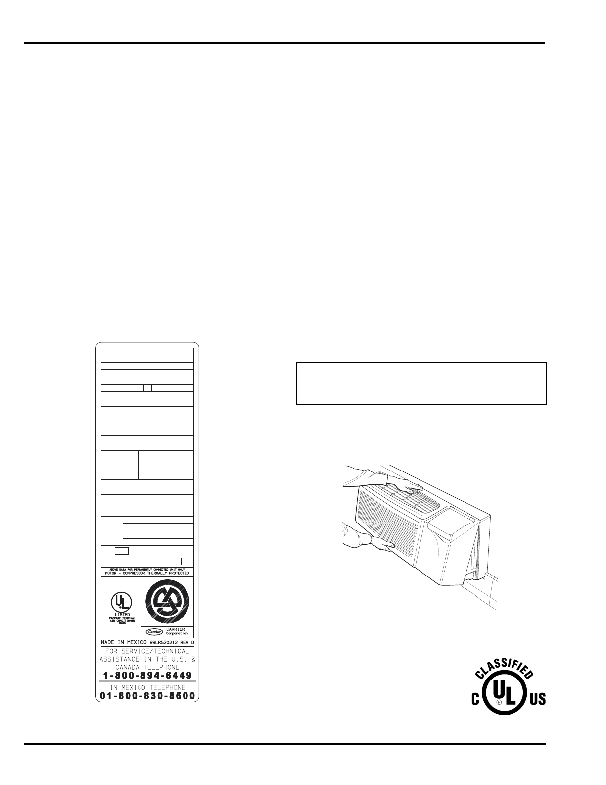
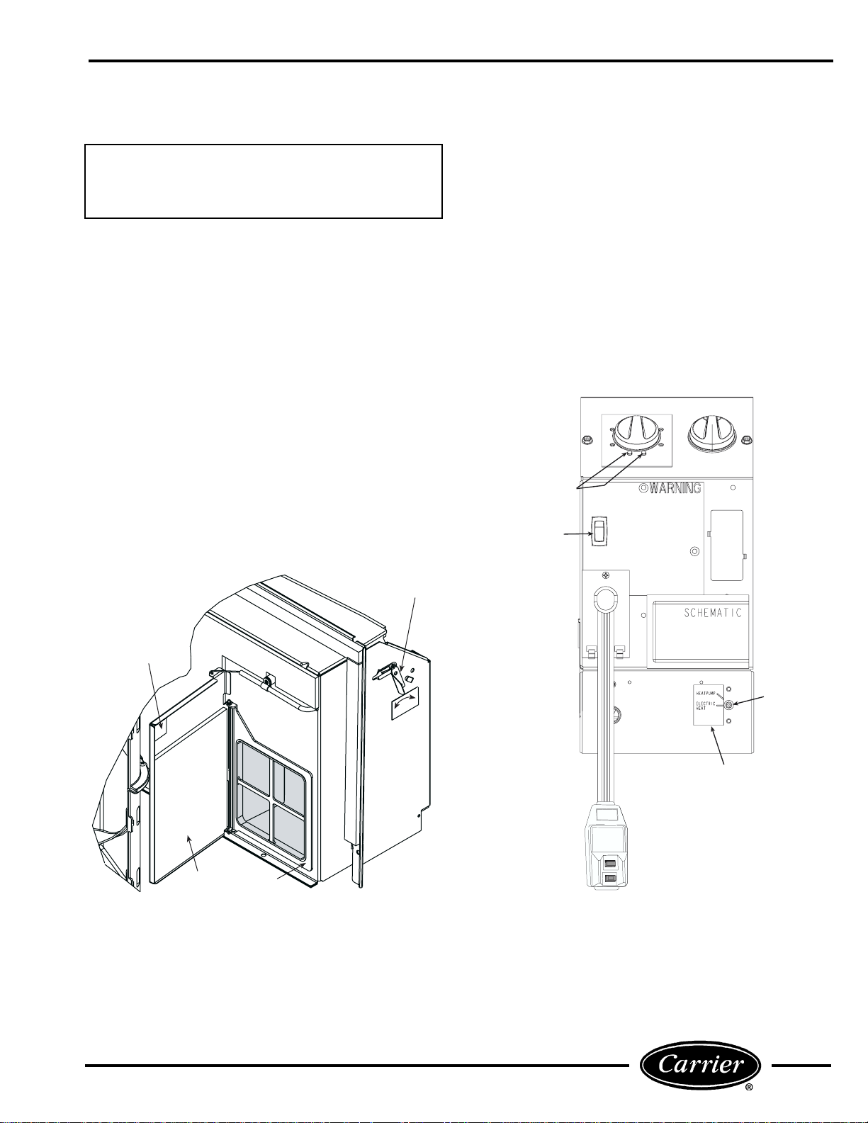
The data information plate (Figure 1) lists the model
number, voltage ranges, and other important electrical
information about this product. Reading and understanding this material is important for proper use of
this unit. To access the information plate, the front
panel must be removed; see Figure 2.
FRONT PANEL
Remove front panel from unit by grasping the panel
firmly at the center top and center bottom. Pull the
panel upward at the bottom and forward at the top to
release magnetic latches and partition hooks. See
Figure 2.
NOTE: Front panel may be secured to chassi s wi th
2 screws located behind indoor air inlet filters. In order
to remove these screws, the filters must be removed
first. Refer to page 11 in this manual for instructions on
removing indoo r air in l et fi lt er s.
IMPORTANT: The front panel has to be off the unit
to complete future checks and installation procedures. Do not reinstall front panel at t his time.
Using Figures 1 and 3 as reference, verify that the
packaged terminal product ordered will operate properly in your facility. If you do not understand the information given or have questions about the product,
please call your local dealer or distributor.
US
C
FIGURE 2 — REMOVING FRONT PANEL
Replacement Package Terminal Air Conditioner,
CLASSIFIED BY UNDERWRITERS LABORATORIES INC., AS TO ELECTRIC
SHOCK, FIRE AND CASUALTY
HAZARDS ONLY. FOR FIELD
INSTALLATION WITH EXISTING
WALL SLEEVES, OUTDOOR LOUVERS, AND INDOOR PANELS AS
SPECIFIED ON THE PRODUCT.
2
Page 3
Series Designation
PTAC (Packaged Terminal Air Conditioner)
Comfort Series
CE – Cooling with Electric Heat
CQ – Heat Pump
Premier Series
PC – Cooling Only
PE – Cooling with Electric Heat
PQ – Heat Pump
Latest Revision
A – Z
Electric Heater Size
2 – 2.3 kW
3 – 3.4 kW
5 – 5.0 kW
Cooling Capacity (nominal)
07 – 7,000 Btuh
09 – 9,000 Btuh
12 – 12,000 Btuh
15 – 15,000 Btuh
FIGURE 3 — MODEL NUMBER NOMENCLATURE
52 PE A 3 12 3 0 1 AA
Chassis Options
AA – Standard
CP – Corrosion Protection
RC – Wall Thermostat Control (Not available
on cooling only units)
RP – Wall Thermostat Control with
Corrosion Protection (Not available on
cooling only units)
Packaging
1 – Domestic
Non-Performance
Changes 0-9
Electrical Data
3 – 230/208-v, 60 Hz
4 – 265-v, 60 Hz
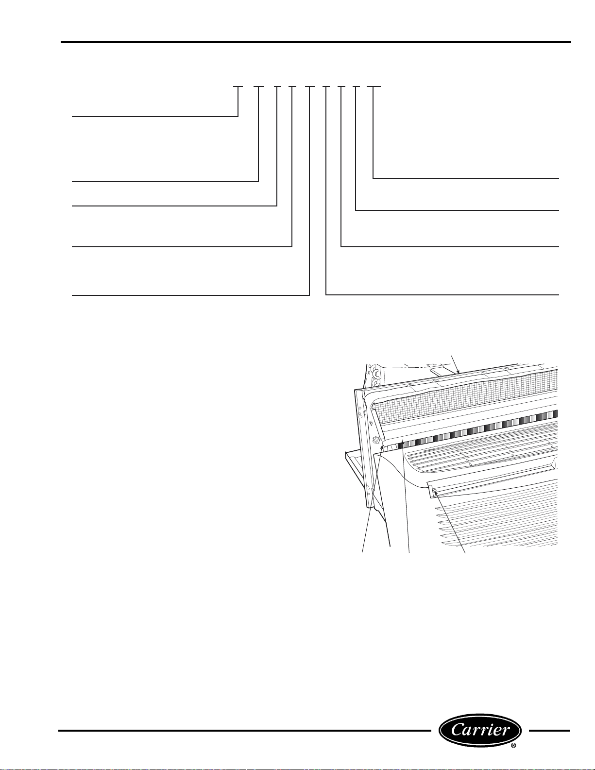
To install the front panel, follow the procedure outlined below:
Replace the unit front panel.
1. Hold the front panel firmly at the center top and
center bottom at a 5 to 10 degree angle from
vertical.
2. Place the top of the front panel onto the unit making sure the top engagement posts have engaged
the slots on the unit. Front panel should be flat
against the top of the unit.
3. Gently lower the front panel onto the cha ssis,
ensuring that the power cord (or conduit) is routed
through the front panel notch. Magnetic la tches at
bottom of front p anel will secure th e front panel to
the unit.
To install locking feature on front panel, be sure front
panel is already installed on unit and follow the steps
below:
NOTE: Two field-supplied no. 8,
1
/2-in. sheet metal
screws are required to secure front panel to chassis.
1. Remove both indoor a ir inlet fi lters to expose fro nt
panel engagement holes. See Figure 4.
2. Secure front panel to chassis by attaching the
field-supplied screws into engagement holes. Do
not over tighten.
3. Replace both indoor air inlet filters.
NOTE: Front panel alignment may have to be
adjusted slightly to line with chassis.
TOP PARTITION
DISCHARGE
DECK
ENGAGEMENT
HOLE
FRONT PANEL
SLOT
FIGURE 4 — FRONT PANEL INSTALLATION
WITH LOCKING FEATURE
3
Page 4
ELECTRICAL DATA
ELECTRICAL SHOCK HAZARD
DO NOT alter cord or plug, and DO NOT use an
extension cord. Personal injury or damage to the
unit may result.
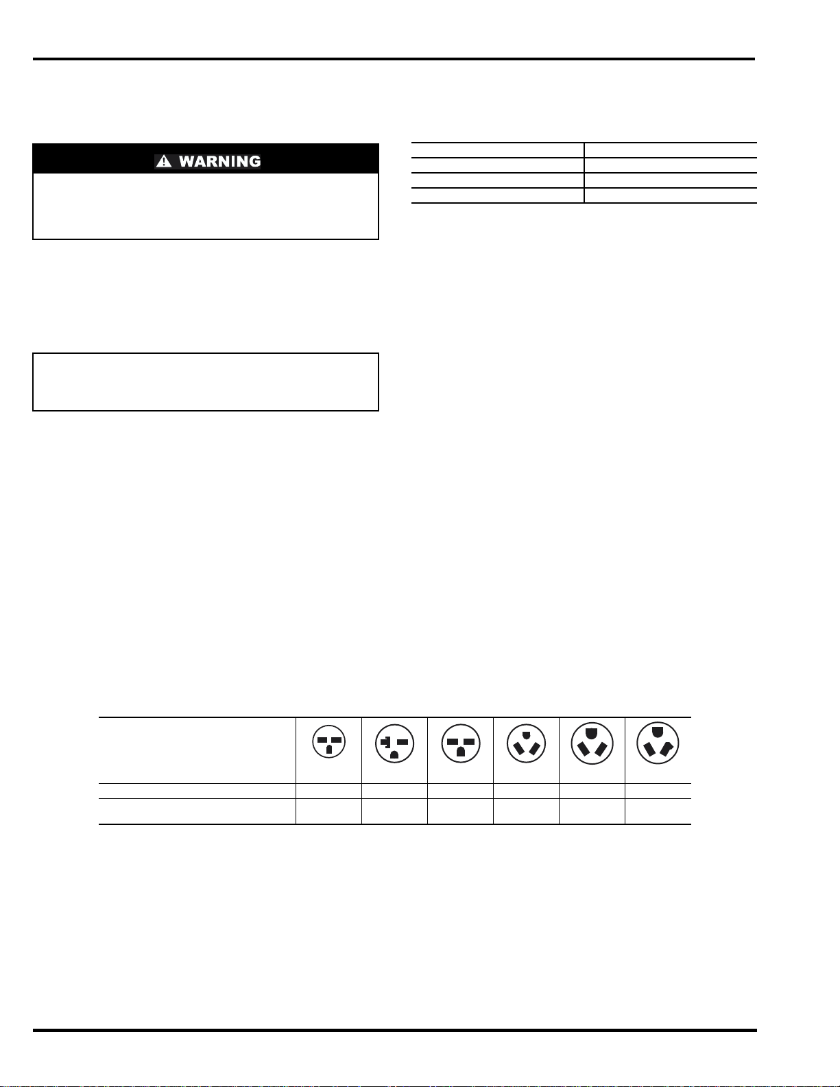
Be sure that your outlet matches the appropriate
blade configuration of the supplied plug and that it is
within reach of the service cord. A hardwire kit is
available as an accessory to change cord-connected
units to hardwired units. (See Accessories table on
page 15.)
IMPORTANT: All standard cord-connected 265-v
units will require a field-installed electrical subbase accessory.
ALL UNITS
■ WIRE SIZE — Use recommended wire size given in
Table 1 and install a single branch circuit. All wiring
must comply with local and national codes. All units
are designed to operate off single branch circuits only.
NOTE: Use copper conductors only.
■ GROUNDING — For safety and protection, the
unit is grounded through the service cord plug or
through separate ground wire provided on hardwired
units. Be sure that the branch circuit or general purpose outlet is grounded.
TABLE 1 — SUGGESTED BRANCH CIRCUIT
WIRE SIZES*
NAMEPLATE AMPS AWG WIRE SIZE†
7.0 to 12 14
12.1 to 16 12
16.1 to 24 10
LEGEND
AWG — American Wire Gage
*Single circuit from main box.
†Based on copper wire at 60 C temperature rating.
VOLTAGE SUPPLY
Check voltage supply at outlet. For satisfactory
results, the voltage range must always be within the
ranges found on the data information plate
(shown in Figure 1).
■ CORD-CONNECTED UNITS — The 250-v field-
supplied outlet must match the plug for the standard
208/230-v units and be within reach of the service
cord. The standard cord-connected 265-v units require
an accessory electrical subbase for operation. See
Accessories table, page 15, for subbase selection. Refer
to Table 2 for proper receptacle and fuse type.
■ POWER CORD PROTECTION — The power cord
for the 230/208-v unit provides both personal shock
protection and power cord fire prevention. Unit power
automatically disconnects when unsafe conditions are
detected. Power to the unit can be restored by pressing
the RESET button on plug head.
Upon completion of unit installation for 230/208-v
models, an operational check should be performed
using the TEST/RESET buttons on the plug head. See
Figure 5.
NOTE: The 265-v models do not incorporate this
feature as they require use of the electrical subbase
accessory.
TABLE 2 — RECEPTACLES AND FUSE TYPES — 250,265 VOLT S
RECEPTACLE
15 Amps 20 Amps 30 Amps 15 Amps 20 Amps 30 Amps
RATED VOLTS 250 250 250 265 265 265
TIME-DELAY TYPE
FUSE (or HACR Circuit Breaker)
LEGEND
HACR — Heating, Air Conditioning, Refrigeration
*May be used for 15-amp applications if fused for 15 amp.
15 20* 30 15 20 30
4
Page 5
INSTALLATION
CHASSIS INSTALLATION
Units are shipped without a sleeve. In applications
where unit is a replacement, it is recommended that a
Carrier sleeve and grille be used.
The 52C and 52P units can retrofit General Electric,
Amana, Trane, and Friedrich sleeves/grilles (be sure
outdoor grille is installed on the sleeve). See Table 3
for details. Carrier Corporation must approve any
other retrofit application.
For competitive retrofit applications, be sure that the
foam seals (factory-installed on the tube sheets) provide a good seal between the outdoor grille and outdoor coil tube sheets. These foam seals provide a
barrier to separate outdoor coil leaving air from mixing with the outdoor incoming air (known as air recirculation).
See Figure 5.
For retrofit applications, foam seals on outdoor coil
tube sheets must make a seal between the coil and
the grille or loss of performance and premature
damage to the major components can result.
TABLE 3 — RETROFIT WALL SLEEVES
MANUFACTURER WALL SLEEVE PART NUMBER
General Electric Metal Sleeve RAB71
Amana Metal Sleeve WS900B
Trane Metal Sleeve SLV149
Friedrich T-Series Metal 11
*FR-SLEEVE-EXT accessory is required for retrofit into Friedrich
(T-Series) wall sleeves.
Plastic Sleeve RAB77
1
/2-in. deep wall sleeve*
Standard depth wall sleeve 16 x 42 x 13
PXWS
3
/4-in.
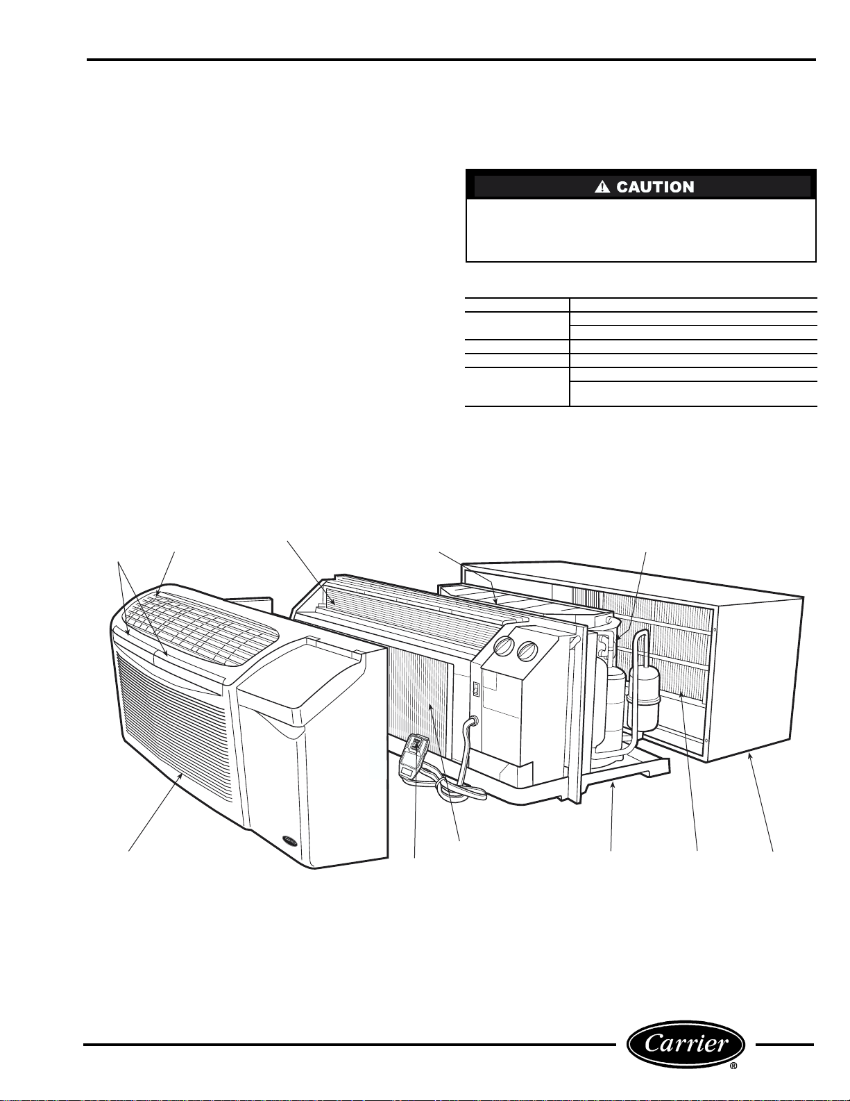
INDOOR-AIR
INLET
FILTERS
FRONT
PANEL
DISCHARGE
GRILLE
WIRE SCREEN
OUTDOOR
ORIFICE
T
E
1
S
.P
R
T
E
S
2
S
IN
.P
R
L
E
U
S
G
G
E
T
IN
R
B
T
E
U
O
C
T
P
E
T
3
P
O
O
.P
T
W
N
A
R
.
E
C
E
R
L
S
E
S
S
.
T
H
E
O
S
T
U
4
B
L
.
D
U
P
L
R
T
IG
T
E
O
S
H
N
S
T.
U
R
F
O
N
E
R
S
IT
D
U
E
O
T
S
B
N
E
.
O
U
T
T
T
U
O
S
N
E
A
I
S
G
A
T
IN
E
S
T
A
B
O
V
E
F
A
I
L
S
INDOOR
PLUG TEST/
COIL
RESET BUTTONS
FIGURE 5 — UNIT COMPONENTS
COIL TUBE
SHEETS
BASEPAN
OUTDOOR
GRILLE
WALL
SLEEVE
5
Page 6
■ COMP ETITIVE SLEEVE PREPARATION
IMPORTANT: Inspect the wall sleeve thoroughly
prior to installation. Manufacturer does not assume
responsibility for costs or damages due to defects in
the sleeve or improper installation.
Disconnect all power to unit to avoid possible electrical shock during installation.
Remove any existing foam baffles that are installed on
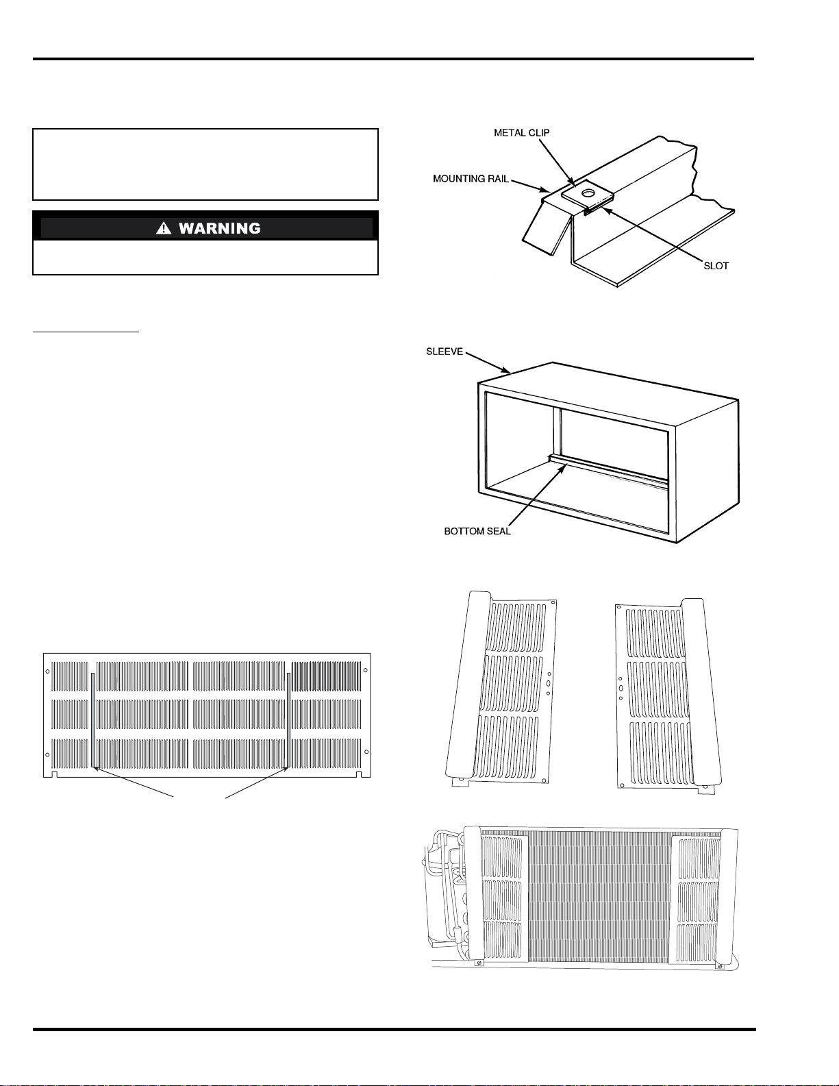
the outdoor grille if present. See Figure 6.
GE Sleeves Only
Metal Wall Sleeve — Remove metal clip on mounting
rail located on left, inside bottom of metal sleeve and
discard. See Figure 7.
Plastic Slee ve — Remove bottom seal from plastic
sleeve. See Figu re 8.
■ INSTALLATION OF A CARRIER WALL SLEEVE
USING A NON-CARRIER GRILLE
This application has become more common due to
pre-manufactured windows with built-in grilles or renovations where a Carrier sleeve is used with an existing non-Carrier grille.
Use of a Carrier wall sleeve with a non-Carrier grille
requires installation of an Accessory Baffle Kit, which
ensures a good seal between the unit and exterior
grille and prevents air recirculation. (See Figures 9
and 10.) Air recirculation is a large contributor to
performance loss and premature damage t o major
components.
FIGURE 7 — REMOVE METAL CLIP ON
GE METAL SLEEVE
FIGURE 8 — REMOVE BOTTOM SEAL FROM
GE PLASTIC SLEEVE
BAFFLES
FIGURE 6 — REMOVE EXISTING BAFFLES ON
COMPETITIVE OUTDOOR GRILLES
FIGURE 9 — ACCESSORY BAFFLE KIT
FIGURE 10 — INSTALLATION COMPLETE
6
Page 7
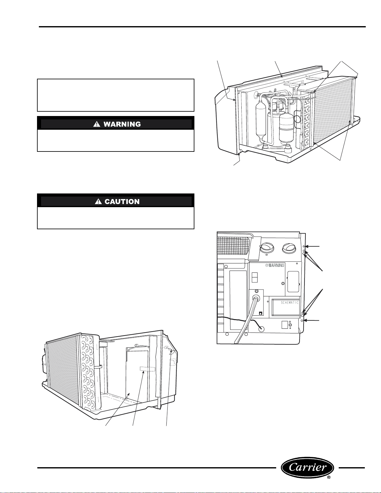
■ INSTALL CHASSIS IN SLEEVE (See Figures 11 to
13)
1. Inspect foam gaskets (top, bottom, both sides) on
chassis. Replace foam gaskets if torn or missing.
IMPORTANT: The gaskets combine with the sleeve
face to create a weather barrier. If the chassis is
installed in a non-Carrier sleeve, this weather barrier may not be effective.
Chassis weighs up to 150 lb. For personal protection,
seek help when lifting the unit. Lift unit by holding
unit basepan.
SIDE
GASKET
TOP
GASKET
FACTORY-INSTALLED
FOAM SEALS
2. If retrofitting into a GE, Amana, Trane, or
Friedrich wall sleeve/grill e, remove any existing
foam seals from competitive manufacturer’s grille
before installing unit.
3. Remove shipping tape from vent door. See Figure 1 1.
Failure to remove shipping tape will prevent fresh
air vent door from opening and may result in damage
to the vent door cable.
4. Carefully remove power cord packing material
and discard.
5. Lift chassis level with wall sleeve.
6. Slide chassis into wall sleeve until foam gaskets
rest firmly against front of wall sleeve. See
Figure 12.
7. Screw chassis to wall sleeve with four 1
3
/4-in. long
screws taped to the control box. Screw holes are
located on both sides of the mo unting angles of th e
chassis. For Carrier wall sleeves, use the top-most
and bottom-most screw holes. For competitive
wall sleeves, line up the correct attachment holes
on the chassis with the holes in the sleeves. See
Figure 13.
BOTTOM
GASKET
FIGURE 12 — UNIT GASKETS
AND TUBE SHEETS
TOP SCREW HOLE
(CARRIER SLEEVE)
COMPETITIVE
MANUFACTURER
SLEEVE
ATTACHMENT
HOLES
BOTTOM SCREW
HOLE
(CARRIER SLEEVE)
COIL TUBE
SHEETS
VENT
DOOR
SHIPPING
TAPE
VENT DOOR
CABLE
FIGURE 11 — LOCATION OF SHIPPING TAPE
ON VENT DOOR
FIGURE 13 — CHASSIS MOUNTING
7
Page 8
WALL THERMOSTAT INSTALLATION
The following instructions apply to RC and RP units
only.
NOTE: Carrier thermostats are recommended. See
Accessories section.
IMPORTANT: Only trained, qualified personnel
and service mechanics should install electrical
accessories on Carrier 52C and 52P series products
per Carrier’s installation instructions. Please contact your local electrical contractor, dealer, or distributor for assistance.
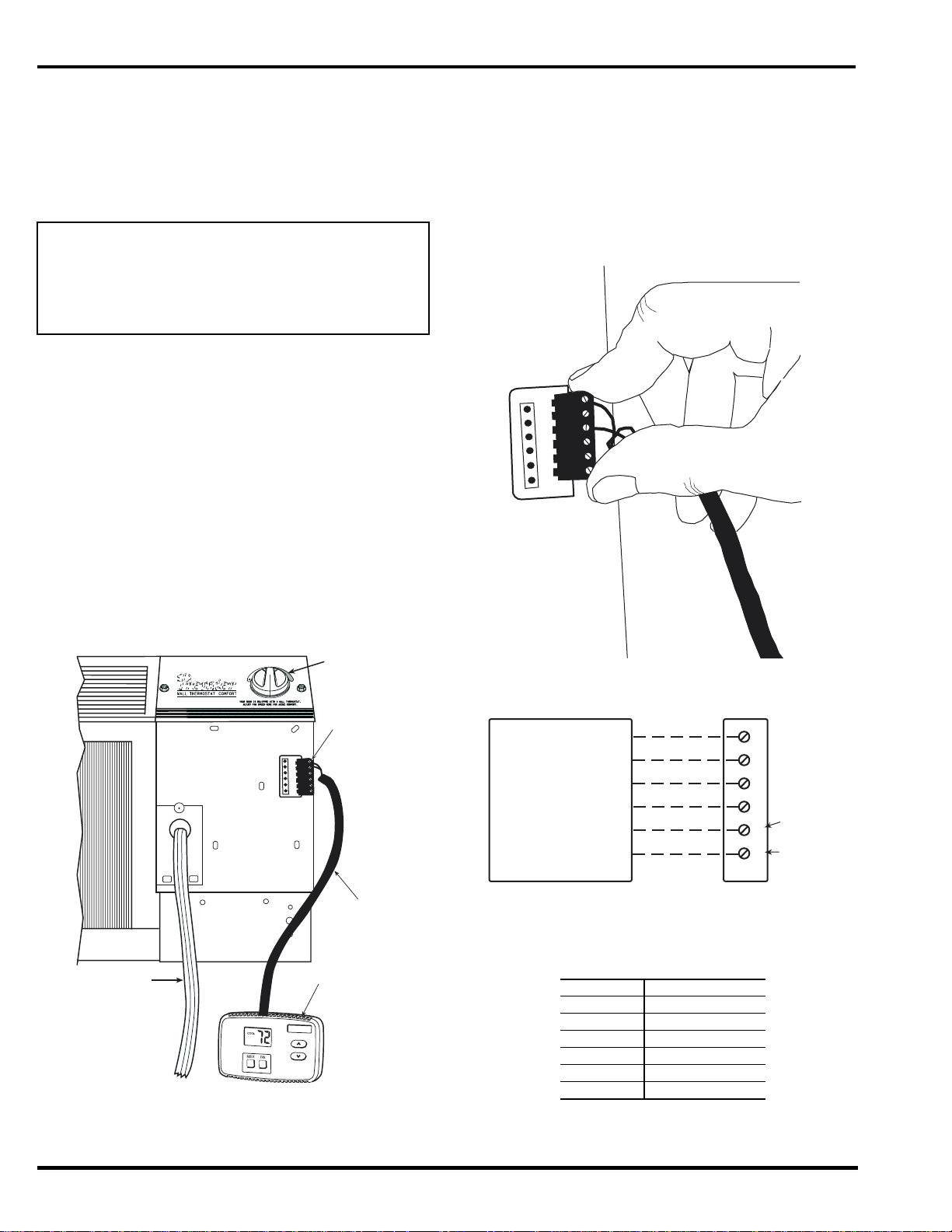
■ THERMOSTAT WIRE ROUTING — Thermos ta t
wire is field supplied. Recommend ed wire gage is 18 t o
20 gage solid thermo stat wire. The rmostat wire should
always be routed around or under, NEVER through,
the wall sleeve. The wire shoul d then be rout ed behind
the front panel to the easily accessible terminal connector. See Figures 14 and 15.
■ INSTALL THERMOSTAT — All remote control
units.
1. Check to be sure power to unit is disconnected.
2. Pull terminal connector to remove.
NOTE: Terminal connector can be removed and replaced to simplify thermostat wiring.
3. Connect wires from terminals on the thermostat
to terminals on chassis terminal board connector.
See Figures 15 and 16.
4. Reinstall terminal connector.
5. Restore power to unit.
NOTE: Refer to thermostat installation instructions
for details on installing thermostat.
NOTE: Fan speed is user-selectable from the control
panel on the unit.
R
Y
W
G
O
C
HI
R
Y
W
G
O
C
FAN SPEED
SELECTOR
SWITCH
TERMINAL
CONNECTOR
THERMOSTAT
WIRE (FIELD
SUPPLIED)
THERMOSTAT
POWER
CORD
LO
FAN SPEED
FIGURE 14 — CONTROL BOX TERMINAL
CONNECTOR FOR WALL THERMOSTAT MODELS
FIGURE 15 — TERMINAL CONNECTOR
REMOVAL AND REPLACEMENT
R
G
TYPICAL
WALL
THERMOSTAT
Y
W
O
C
TERMINAL
BLOCK
SEE
NOTE #1
SEE
NOTE #2
NOTES:
1. Use terminal “O” for heat pump connection only.
2. Terminal C (common) is typically only required for digital thermostats.
3. See table below for terminal descriptions.
TERMINAL DESIGNATION
R 24 VAC
G Fan
Y Compressor
W Electric Heat
O Reversing Valve
C Common
FIGURE 16 — WIRING CONNE CTIONS
8
Page 9
OPERATION
IMPORTANT: When unit is first started, high
humidity conditions can cause co ndensation to form
on discharge grille. Keep doors and windows closed.
Room humidity decreases and moisture evaporates.
COMFORT CONTROLS
■ ADJUST AIRFLOW DIRECTION — The discha rge
air grille is mounted on the front panel so that the air
discharges forward. If upward discharge is required,
remove the grille by removing screws on back of front
panel. Rotate grille 180 degrees and reinstall on the
front panel.
■ ADJUST VENT — The vent handle is on the left
side of the unit. Turn handle to open or close vent.
Vent will remain in last desired position until handle
is turned again. Magnet will ensure positive closure.
See Figure 17.
■ SETTING TEMPERATURE LIMITS — Setting tem-
perature limits on the unit provides the user a
restricted range of temperature control. See Figure 18.
NOTE: This adjustment is option al and is not applicable to remote control units.
The temperature limits are factory set to full range,
which is 60 F to 90 F. To set restricted rotation of the
temperature control knob:
1. Remove front panel.
2. Remove temperature control knob to expose temperature limiter.
3. Remove standoff pins from the 60 F and 90 F indicator holes.
4. Replace standoff pin in hole for desired minimum
temperature.
5. Replace standoff pin in hole for desired maximum
temperature.
6. Reinstall temperature control knob.
7. Reinstall front panel.
NOTE: Temperature indicators stamped on temperature limiter are approximate and represent degrees F.
75
70
65
60
90
TEMPERATURE
CONTROL
STANDOFF
PINS
FAN CYCLE
SWITCH
80
85
CON
CYC
MAGNET
VENT
DOOR
VENT
FILTER
FIGURE 17 — VENT DOOR
VENT HANDLE
E
S
O
L
C
N
PE
O
SET
SCREW
OUTDOOR
THERMOSTAT
(HEAT PUMP
UNITS ONLY)
S
L
I
A
F
E
V
O
B
A
T
S
E
T
S
I
E
S
U
T
O
N
O
D
.
E
S
U
R
O
F
N
I
A
G
A
N
O
T
T
U
B
T
E
S
E
R
S
S
E
R
P
.
4
.
T
H
G
I
L
D
L
U
O
H
S
T
I
N
U
N
O
T
T
U
B
T
S
E
T
S
S
E
R
P
.
3
.
E
L
C
A
T
P
E
C
E
R
R
E
W
O
P
O
T
N
I
G
U
L
P
.
2
.
N
O
T
T
U
B
T
E
S
E
R
S
S
E
R
P
.
1
T
E
S
T
IN
G
FIGURE 18 — OPERATING CONTROLS
9
Page 10
OPERATING CONTROLS
The following controls are located on the front of the
control box door, under front panel. To obtain access to
operating controls, remove the unit front panel as
shown on page 2. See Figure 18.
■ FAN CYCLE SWITCH — (Typically available at
wall thermostat on RC or RP units.) This allows the
fan to operate in two modes:
CON (Continuous)
run continuously, circulating air even when the temperature setting has been satisfied. This switch helps
to maintain the room temperature closer to the thermostat setting. Use this switch po sition when maximum comfort is desired. This is the factory default
setting.
CYC (Cycle)
and off with the compressor during heating or cooling.
The fan stops when the temperature setting is satisfied. This results in longer unit off-time and wider
variations in room temperature and humidity.
■ OUTDOOR THERMOSTAT (52CQ and 52PQ HEAT
PUMP UNITS ONLY) — If the setscrew is left at the
factory setting (in the heat pump position), the unit
will operate in the reverse cycle heating mode. See
Figure 18. When the temperature of the outdoor coil
reaches 20 F (approximately 35 F outdoor air temperature), the compressor will shut down as unit is no
longer capable of adequate heating in heat pump
mode. The electric heater then becomes the primary
heating source. The electric heater remains on until
the temperature of the outdoor coil reaches 40 F; then
the electric heater is shut off and the compressor is
energized. Once the compressor is energized, the heat
pump again becomes the primary heating source.
To set unit to operate in electric heat mode only, turn
the setscrew to the electric heat positi on. See Fi gure 18 .
— This setting allows the fan to
— This setting allows the fan to cycle on
IMPORTANT: If setscrew on standard heat pump
unit is set to electric heat mode operation, the compressor is disabled for both heating and cooling
operations. If setscrew on heat pump unit with wall
thermostat control is set to electric heat mode
operation, the compressor will be disabled only for
heating operation.
OPERATING MODES (See Figures 19
and 20.)
■ OUTSIDE AIR — To bring outside air into occupied
space, turn the vent handle to the full open position.
See Figure 17.
■ OFF — The OFF mode terminates unit operation.
■ FAN— The FAN mo de will circulate air in the space
at high speed and at high or low speed for cool ing onl y
models.
■ HIGH HEAT OR HIGH COOL — Select mode and
rotate temper atu r e kn ob to d esi re d c omfo r t le v el. T hi s
function provides maximum heating or cooling, and is
recommended to raise or lower the room temperature
quickly.
■ LOW HEAT OR LOW COOL — Select mode and
rotate temper atu r e kn ob to d esi re d c omfo r t le v el. T hi s
function provides minimum heating or cooling with
maximum dehumidification and quietest operation.
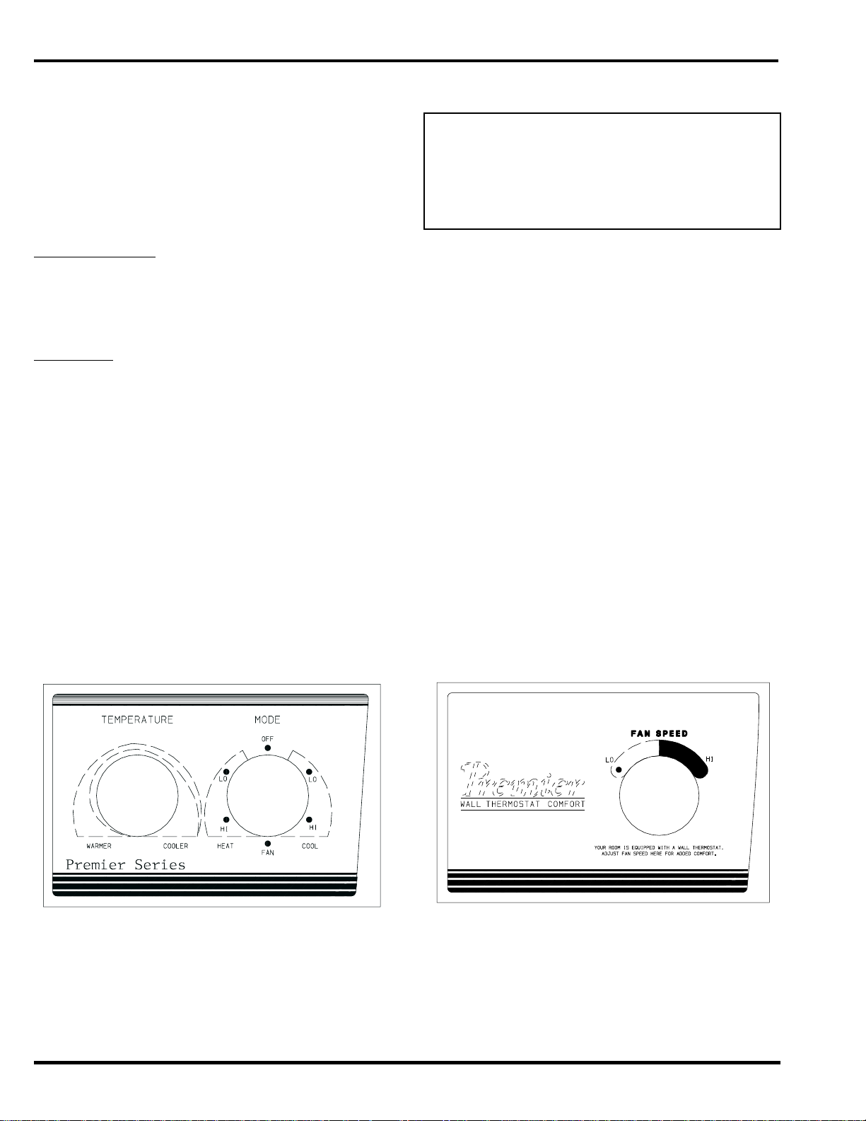
■ FAN SPEED CONTROL FOR 52P AND 52C WALL
THERMOSTAT MODELS — For maximum comfort,
fan speed is user selectable at the unit. See Figure 20.
FIGURE 19 — 52P UNIT CONTROLS SHOWN
WALL THERMOSTAT CONTROL SHOWN
FIGURE 20 — 52P UNIT WITH
(Blank Plate)
10
Page 11
CARE AND MAINTENANCE
In order to maintain proper performance of your packaged terminal air conditioner or heat pump, it is very
important that the fan and outdoor coil, the blower
wheel, blower scroll, electric heater, and all drain passages are thoroughly cleaned at least once per year.
Carrier recommends that as a minimum, the cleaning
should be conducted prior to the start of each heating
season. The air inlet filters should be cleaned every
month.
Depending on local condition s, more freq uent cleaning
of the unit may be required to ensure optimum performance and long operating life. Examples of these special conditions include areas where construction dust
or heavy airborne dirt is found, or environments that
promote the growth of fungus.
Some local conditions and environments can cause
fungi to grow inside the air conditioner, especially on
indoor blower section. Dried fungi, dirt and other
foreign material are fire hazards. Be sure to clean
unit according to the instructions that follow.
INDOOR-AIR INLET FILTERS
■ INDOOR-AIR INLET FILTERS should be cleaned
once each month.
FIGURE 21 — INDOOR-AIR INLET
FIL TER REMOVAL
IMPORTANT: Filters may become clogged if not
cleaned properly. Clogged filters will restrict airflow which may lead to severe component damage
and efficiency loss.
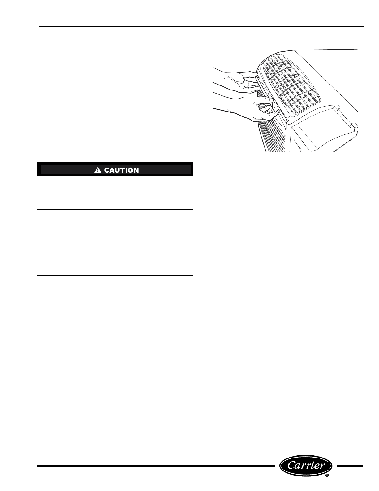
■ CLEANING INDOOR-AIR INLET FILTER — Two
interchangeable air filters are located on the backside
of the front panel. Each can be removed and cleaned
one at a time. To remove and clean the filter, follow the
steps below:
1. Grasp filter with both hands.
2. Gently pull the filter up and away from the unit.
See Figures 5 and 21.
3. To clean filter, use a vacuum or soft bristle brush
with a small amount of mild deterg ent.
NOTE: If detergent is used, remove any detergent
residue with a gentle stream of clean water.
4. Allow filters to air dry.
5. Re-insert dry filters back into front panel.
Additional filters are available in multi-packs. Refer to
Accessories section.
11
Page 12

EXTERNAL PARTS
■ EXTERNAL PARTS include the polymer sleeve and
grilles. The sleeve manufact urer recommends cleaning
the surface, including the grilles, with household
detergent and water.
VENT HANDLE
MAGNET
INTERNAL PARTS
■ INTERNAL PARTS should be cleaned at least once
during the year. The outdoor vent filter should be
cleaned at least once during a cooling or heating
season.
Internal parts that should be cleaned include the following (see Figures 5, 22, and 23):
• Outdoor vent filter
•Basepan
• Outdoor orifice and fan
• Indoor and outdoor refrigeration coils
• Indoor blower wheel
• Wire screen
• Scroll
• Wall sleeve internal surfaces
• Outdoor grille
P
O
VENT
DOOR
VENT
FILTER
FIGURE 22 — OUTDOOR VENT FILTER
(Left Side of Chassis)
SE
CLO
N
E
SCROLL
BLOWER
WHEEL
FIGURE 23 — BLOWER WHEEL AND SCROLL
12
Page 13

PREVENTATIVE
MAINTENANCE
Preventative maintenance is essential to proper unit
operation, efficiency and longevity. To assure equipment operates properly it must be properly maintained. Equipment operation should be checked and
verified several times during each year.
During regular unit inspection and maintenance, follow the guidelines below:
• Wash both sides of outdoor coil
• Wash basepan and outdoor vent filter
• Wash the indoor coil
• Clean the blower wheel and front panel
• Clean or install new indoor-air inlet filter(s)
• Ensure knobs are secure and operable
• Inspect cord and receptacle
• Secure electrical connections
• Ensure front panel is properly mounted and not
damaged
• Ensure wall sleeve is installed properly
• Ensure heat and cool cycles operate properly
• Check power cord protective device by pressing the
TEST button, then pressing the RESET button.
13
Page 14

TROUBLESHOOTING
POSSIBLE CAUSES SOLUTIONS
UNIT DOES NOT START
• Unit may have become unplugged • Check that plug is securely in wall receptacle.
• RESET button on cord or plug may have tripped • Check RESET button on cord or plug. See Note 1.
• Fuse may have blown • Replace the fuse. See Note 1.
• Circuit breaker may have been tripped • Reset circuit breaker. See Note 1.
• Unit mode dial may be set to the OFF position • Switch mode dial to an operating mode.
UNIT NOT COOLING/HEATING ROOM
• Unit air discharge section is blocked • Make sure that curtains, blinds or furniture are not restricting or
• Temperature setting is not high or low enough • Reset to a lower or higher temperature setting.
• Unit air filters are dirty • Remove and clean filters.
• Room is excessively hot or cold when unit is started • Allow sufficient amount of time for unit to heat or cool the room.
• Vent door left open • Close vent door.
UNIT MAKING NOISES • Clicking, gurgling and whooshing noises are normal during operation of
WATER DRIPPING OUTSIDE • If a drain kit has not been installed, condensation run-off during
WATER DRIPPING INSIDE
• Wall sleeve is not installed level • Wall sleeve must be installed level for proper drainage of condensation.
ICE OR FROST FORMS ON INDOOR COIL
• Low outdoor temperature • When outdoor temperature is approximately 55 F or below, frost
• Dirty filters • Remove and clean filters.
blocking unit airflow.
Start heating or cooling early before outdoor temperature, cooking
heat or gatherings of people make room uncomfortable.
unit.
very hot and humid weather is normal. See Note 2. If a drain kit
has been installed and is connected to a drain system, check
gaskets and fittings around drain for leaks and plugs.
Check that installation is level and make any necessary adjustments.
may form on the indoor coil when unit is in Cooling mode. Switch
unit to FAN operation until ice or frost melts.
NOTES:
1. If circuit breaker is tripped, fuse is blown or RESET button on cord or plug is tripped more than once, contact a qualified electrician.
2. If unit is installed where condensation drainage could drip in an undesirable location, an accessory drain kit should be installed and connected to
drain system.
14
Page 15

ACCESSORIES
ACCESSORY FORM NUMBER PART NUMBER DESCRIPTION
Wall Sleeves 52S-48SI WALL-SLEEVE-1PK Non-Insulated Polymer Wall Sleeve, 1 per pack
52S-50SI SLEEVE-STEEL-1PK Insulated Metal Wall Sleeve, 1 per pack
52S-49SI SLEEVE-EXT24-1PK Extended Metal Wall Sleeve for Deep Wall Applications (24 in. deep), 1 per pack
52C,P-26SI FR-SLEEVE-EXT Friedrich wall sleeve extension to retrofit Carrier PTAC unit into Friedrich 111/2″deep
Exterior Grilles* 52S-59SI GRILLE-ALU-STAMP Stamped Aluminum Exterior Grille, Clear Finish
Subbase 52C,P-1SI SUBBASE-NON-ELEC Non-electrical Subbase
Subbase
Field-Installed
Kits
Electrical
Connections
Condensate
Drain Kit
Wall
Thermostats
Wall Thermostat
Interface
Retrofit Kit
Replacement
Filters
Energy
Management
Locking Security
Control Door
Lateral Duct Kit 52C,P-25SI LATERAL-DUCT Ductwork to allow one unit to heat and cool two rooms (plenum plus extension duct and registers)
Power Ven t
Retrofit Kit
Air/Curtain
Deflector
Touch-Up Paint N/A CARRIER-TOUCH-UP Touch up paint for repainting scratches or chips.
*Custom co lors are also available.
52S-65SI
52S-60SI GRILLE-ALU-CLEAR Aluminum Architectural Exterior Grille, Clear Finish
52C,P-31SI BAFFLE-KIT-1PK Ensures good air seal and prevents air recirculation when Carrier sleeve is used with a non-Carrier grille.
52C,P-2SI SUBBASE-230V-15A Electrical subbase with factory-installed 208/230V, 15 amp receptacle
52C,P-17SI SUBBASE-265V-15A Electrical subbase with factory-installed 265V, 15 amp receptacle
52C,P-3SI SUBBASE-HARDWIRE Electrical subbase with factory-installed hardwire kit (230/208V and 265V)
52C,P-4SI SUBBASE-SWITCH Field-Installable Switch kit for an electrical subbase
52C,P-5SI SUBBASE-FUSE-15A Field-Installed Fuse Kit (15 amp) for electrical subbase
52C,P-11SI HARDWIRE-KIT-1PK Permanent power connection to the unit (includes 36″of flexible conduit and unit-mounted
52C,P-19SI CONDUIT-INTF-4PK Interface kit for field-supplied conduit to provide permanent power connection
52S-53SI DRAIN-KIT-4PK Attaches to wall sleeve for controlled internal or external disposal of condensate 4 per pack
N/A HH01AD045 Electro-mechanical Wall Thermostat (Heat/Cool and Heat Pump)
52C,P-30SI RC-FIELDKIT230HC Field-installed wall thermostat retrofit kit to convert a standard 230V Heat/Cool unit to an
52C,P-34SI 2SPEED-TSTAT-KIT Field-installed automatic heat/cool changeover thermostat with 2-speed fan control at thermostat.
N/A TSTAT-COVER-6X7 Clear plastic locking thermostat cover prevents unauthorized access to thermostat.
N/A TSTAT-COVER-7X10 Clear plastic locking thermostat cover prevents unauthorized access to thermostat. Cover for
N/A AIR-FILTER-10PK Replacement air filters in package of 10
52C,P-24SI EM-KIT Allows unit to be turned on and off from a remote location (includes freeze guard protection)
52C,P-23SI SECURITY-DOOR Key-locking security door to prevent access to heating and cooling controls
52C,P-32SI PWR-VENT-DOOR230 Power vent with automatic door that opens and closes when the fan turns on and off (230V).
52C,P-9SI DEFLECTOR-1PK Lateral air deflector, with individually adjustable louvers, to enhance air circulation, 1 per pack
52C,P-21SI CURTDFL-52CP-1PK Curtain deflector for 52C and 52P models — prevents curtains from blowing into
WALL-SLEEVE-9PK Non-Insulated Polymer Wall Sleeve, 9 per pack
SLEEVE-INSUL-1PK Insulated Polymer Wall Sleeve, 1 per pack
SLEEVE-EXT26-1PK Extended Metal Wall Sleeve for Deep Wall Applications (26 in. deep), 1 per pack
SLEEVE-EXT28-1PK Extended Metal Wall Sleeve for Deep Wall Applications (28 in. deep), 1 per pack
SLEEVE-MOLDING Molding kit to trim the wall sleeve to the wall
(T Series) wall sleeve. 1 per pack
GRILLE-PLA-BROWN Polymer Architectural Rear Grille, Brown
GRILLE-PLA-BEIGE Polymer Architectural Rear Grille, Beige
GRILLE-ALU-WHITE Aluminum Architectural Exterior Grille, White
GRILLE-ALU-BRONZ Aluminum Architectural Exterior Grille, Light Bronze
GRILLE-ALU-MBRNZ Aluminum Architectural Exterior Grille, Medium Bronze
GRILLE-ALU-BROWN Aluminum Architectural Exterior Grille, Brown (Dark Bronze)
GRILLE-ALU-BEIGE Aluminum Architectural Exterior Grille, Beige
GRILLE-ALU-ALPIN Aluminum Architectural Exterior Grille, Alpine (matches Carrier Wall Sleeve)
GRILLE-ALU-PEACH Aluminum Architectural Exterior Grille, Peach
GRILLE-ALU-MELON Aluminum Architectural Exterior Grille, Melon
GRILLE-ALU-LGREY Aluminum Architectural Exterior Grille, Light Grey
GRILLE-ALU-SGREY Aluminum Architectural Exterior Grille, Slate Gray
GRILLE-ALU-RDBRK Aluminum Architectural Exterior Grille, Red Brick
GRILLE-ALU-BLUE Aluminum Architectural Exterior Grille, Blue
GRILLE-ALU-GREEN Aluminum Architectural Exterior Grille, Green
SUBBASE-230V-20A Electrical subbase with factory-installed 208/230V, 20 amp receptacle
SUBBASE-230V-30A Electrical subbase with factory-installed 208/230V, 30 amp receptacle
SUBBASE-265V-20A Electrical subbase with factory-installed 265V, 20 amp receptacle
SUBBASE-265V-30A Electrical subbase with factory-installed 265V, 30 amp receptacle
SUBBASE-FUSE-20A Field-Installed Fuse Kit (20 amp) for electrical subbase
SUBBASE-FUSE-30A Field-Installed Fuse Kit (30 amp) for electrical subbase
connector, 230/208V and 265V) 1 per pack
(230/208V and 265V) to the unit. Kit includes Molex connector for easy connect/disconnect.
4 per pack
TSTATCCBPC01-B Value Series Electronic Thermostat w/Digital display (Heat/Cool Models)
TSTATCCBPH01-B Value Series Electronic Thermostat w/Digital display (Heat Pump Models)
TSTATCCPAC01-B 7-Day Programmable Electronic Thermostat (Heat/Cool Models)
TSTATCCPHP01-B 7-Day Programmable Electronic Thermostat (Heat Pump Models)
RC-FIELDKIT230HP Field-installed wall thermostat retrofit kit to convert a standard 230V Heat Pump unit to an
RC-FIELDKIT265HC Field-installed wall thermostat retrofit kit to convert a standard 265V Heat/Cool unit to an
RC-FIELDKIT265HP Field-installed wall thermostat retrofit kit to convert a standard 265V Heat Pump unit to a
PWR-VENT-DOOR265 Power vent with automatic door that opens and closes when the fan turns on and off (265V).
RC unit. Wall thermostat sold separately (can be used to convert a cool only unit to RC).
RC unit. Wall thermostat sold separately.
RC unit. Wall thermostat sold separately (can be used to convert a cool only unit to RC).
RC unit. Wall thermostat sold separately.
Cover for use with non-programmable and electro-mechanical thermostats.
Outside dimensions: 6
use with programmable thermostats. Outside dimensions: 71/4″ x 93/4″ x 33/8″. 1 per pack
discharge air stream. 1 per pack.
NOTE: Curtain deflector for previous models are also available. Contact Carrier Representative.
1
/2″ x 71/2″ x 215/16″. 1 per pack
15
Page 16

Page 17

normal maintenance as outlined in the owner’s manual.
installation.
tion. This is the responsibility of the installer.
or any other damages due to the inadequacy or interruption of electrical
services.
unauthorized alteration, improper ser vicing or operation.
environment, or other conditions beyond the control of CARRIER.
EXCEPTION TO CORROSIVE ENVIRONMENT IN ABOVE PARAGRAPH —
Packaged terminal units (52 Series) built with corrosion protection are exempt
from the exclusion — “Corrosive Environment.” The unit model number is
identified on the nameplate with a CP suffix.
plied or designated by CARRIER and which are specifically covered under
this warranty.
and Canada.
responsibility of the selling dealer or the authorized Room Air Conditioner
service station.
MERCIAL DAMAGE OF ANY NATURE WHATSOEVER. Some states do not
allow the exclusion or limitation of incidental or consequential damages, so
the above limitation or exclusion may not apply to you.
1. CLEANING REQUIRED PRIOR TO WARRANTY REPAIR.
2. Standard maintenance, cleaning or damage resulting from failure to perform
3. Instruction on methods of control and use of air conditioning unit after initial
4. Damage or repairs needed as a consequence of faulty installation or applica-
5. Failure to star t due to voltage conditions, blown fuses, open circuit breakers
6. Damage or repairs needed as a consequence of any misapplication, abuse,
CARRIER WILL NOT BE RESPONSIBLE FOR:
7. Damage as a result of floods, winds, fires, lightning, accidents, corrosive
8. Reimbursement for replacement parts or repair services which are not sup-
9. CARRIER products installed outside the continental U.S.A., Alaska, Hawaii
10. Shipping damage or damage as a result of transporting the unit. This is the
11. ANY SPECIAL, INDIRECT OR CONSEQUENTIAL PROPERTY OR COM-
12. Warranty coverage of accessory items (wall thermostats, wall sleeves, etc.).
NOTE: Service and Maintenance items excluded in this warranty may be covered by
a separate service agreement through the seller at time of purchase.
This warranty gives you specific legal rights, and you may also have other rights which vary from state to state.
Carrier
Packaged Terminal
Air Conditioner Warranty
FULL ONE-YEAR WARRANTY — During the first year after purchase, CARRIER
will, through its authorized independent servicing dealers or service stations*, and
free of charge to the user or subsequent users, repair or replace any par ts which
are defective in material or workmanship. The replacement part can be a new or
remanufactured part as provided at CARRIER’S sole option.
FULL EXTENDED FOUR-YEAR WARRANTY ON SEALED REFRIGERATION
SYSTEM ONLY — During the second through fifth years after date of original pur-
chase, CARRIER will, through its authorized servicing dealers and service stations*
and free of charge to the end user or subsequent users, repair or replace the
compressor, condenser, evaporator or connecting tubing if defective in material or
workmanship. This includes system refrigeration charge. The replacement part can
be new or a remanufactured part as provided at CARRIER’S sole option.
LIMITED EXTENDED FOUR-YEAR WARRANTY ON NON-SEALED REFRIGER-
ATION SYSTEM ONLY — During the second through fifth years after date of origi-
nal purchase, Carrier will, through its authorized servicing dealers and service
stations and free of charge to the end user or subsequent users, repair or replace
any non-sealed system part (motor, solenoid, thermistor, thermostat, relays, switch,
capacitor, overload, drain valve, bulb heater, fan, stator) if defective in material or
workmanship. The replacement part can be new or a remanufactured par t at
CARRIER’S sole option. THIS LIMITED WARRANTY DOES NOT INCLUDE
LABOR, user is responsible for labor, including cost of diagnosis of problem,
removal and transportation of the air conditioner to and from the service center, and
reinstallation charges necessary to accomplish repair.
LIMITATION OF WARRANTIES — ALL IMPLIED WARRANTIES (INCLUDING
IMPLIED WARRANTIES OF MERCHANTABILITY) ARE HEREBY LIMITED IN
DURATION TO THE PERIOD FOR WHICH EACH LIMITED WARRANTY IS GIVEN
AND APPLIES. SOME STATES DO NOT ALLOW LIMITATIONS ON HOW LONG
AN IMPLIED WARRANTY LASTS, SO THE ABOVE LIMITATION MAY NOT APPLY
TO YOU. THE EXPRESSED WARRANTIES MADE IN THIS WARRANTY ARE
EXCLUSIVE AND MAY NOT BE ALTERED, ENLARGED, OR CHANGED BY ANY
DISTRIBUTOR, DEALER, OR OTHER PERSON WHATSOEVER.
ALL WORK UNDER THE TERMS OF THIS WARRANTY SHALL BE PERFORMED
DURING NORMAL WORKING HOURS. ALL REPLACEMENT PARTS, WHETHER
*Authorized independent dealers or service stations are registered with Carrier Air Conditioning through its distributor organization.
NEW OR REMANUFACTURED, ASSUME AS THEIR WARRANTY PERIOD ONLY
THE REMAINING TIME PERIOD OF THIS WARRANTY.
Catalog No. 530-122 (Rev. 3/02)
17
Page 18

Carrier Air Conditioning
Consumer Relations Department
Carrier Parkway, P.O. Box 4808
Syracuse, New York 13221
Telephone: 1-800-894-6449
3. CONTACT THE CARRIER DISTRIBUTOR SERVING YOUR AREA.
Your dealer can provide the distributor’s name or you can consult your
yellow pages.
4. CONTACT CARRIER IF A SATISFACTORY SOLUTION IS NOT
REACHED IN STEPS 2 AND 3.
IF YOUR AIR CONDITIONER DOES NOT WORK, FOLLOW THESE STEPS IN ORDER:
1. CHECK THE THINGS YOU CAN DO YOURSELF. These include
being sure the air conditioner is plugged in firmly in an appropriate
receptacle, checking the fuse or circuit breaker and ensuring its re-
placement or resetting, if necessary, and rereading the instruction
book to ensure that all controls are set properly. By doing this you
can save money. Many unnecessary service calls in the serviceman
doing what the owner can do for him or herself.
2. CONTACT YOUR DEALER OR THE RECOMMENDED CARRIER
AUTHORIZED SERVICE CENTER. They have been set up
to handle the great majority of all possible service problems. The
quickest, surest and best way to get your air conditioner back in
service is to use this step before proceeding further.
Carrier Corporation
Copyright 2004 Carrier Corporation
Manufacturer reserves the right to discontinue, or change at any time, specifications or designs without notice and without incurring obligations.
Book 1 4
Tab 9a 11a
PC 132 Catalog No. 535-20066 Printed in U.S.A. Form 52C,P-2SO Pg 18 10-04 Replaces: 52C,P-1SO
Page 19

52C,P-1S0
OBLIGACIONES
PC 132 Catalogo No. 535-20066 Printed in U.S.A. Forma 52C,P-2S0 10-04 Sustituye:
EL FABRICANTE SE RESERVA EL DERECHO DE MODIFICAR O DESCONTINUAR LAS ESPECIFICACIONES DE DISEÑO SIN INCURRIR EN
2. CONTACTE AL DISTRIBUIDOR CARRIER O AL CENTRO
cortacircuito disparado. Si es necesario repase el manual de
instrucciones para verificar que los controles están bien ajustados.
Haciendo esto Usted mismo, ahorra dinero. Tal vez el técnico de
servicio venga y haga las cosas que pudo haber hecho Usted
mismo.
AUTORIZADO DE SERVICIO CARRIER RECOMENDADO. Ellos
están preparados para resolver la mayoría de los posibles problemas
de servicio. El mejor medio, más rápido y seguro para poner de
nuevo a funcionar su acondicionador es el seguir esta
recomendación antes de seguir adelante.
4. CONTACTE DIRECTAMENTE A CARRIER SI NO ENCONTRÓ UNA
Carrier Air Conditioning
Consumer Relations Departament
Carrier Parkway, P.O. Box 4808
Syracuse, New York 13221
Telefono: 1-800-894-6449
Carrier México, S.A. De C.V.
Galeana 469 Ote.
Santa Catarina, N.L.,
C.P. 66350 México
Teléfono: 01.800.830.8600 (México)
SOLUCIÓN SATISFACTORIA EN LOS PASOS 2 Y 3.
Telefónico.
1. VERIFIQUE LAS COSAS QUE PUEDE HACER USTED MISMO.
Esto incluye verificar si la unidad es bien conectada y en el contacto
correcto, verificar que los fusibles no están quemados o el
Corporación Carrier
SI SU ACONDICIONADOR DE AIRE NO FUNCIONA, SIGA LOS PASOS A CONTINUACIÓN:
3. CONTACTE AL DISTRIBUIDOR CARRIER QUE MÁS CERCA DE
USTED. Su distribuidor independiente puede darle su nombre o bien,
Usted puede consultarlo en la Sección Amarilla del Directorio
Page 20

R
* La red de distribuidores independientes autorizados está registrada en CARRIER a través de su organización de distribución.
Catalog No. 530-122 (Rev. 3/02)
Esta garantía le otorga derechos legales específicos, y Usted puede tener algunos otros derechos los cuales pueden variar entre los estados de la unión americana.
MISMO PERÍODO DE GARANTÍA RESTANTE.
TODOS LOS TRABAJOS BAJO LOS TÉRMINOS DE ESTA GARANTÍA DEBERÁN SER
REALIZADOS DURANTE HORAS DE TRABAJO NORMALES. TODAS LAS PARTES
DE REEMPLAZO, YA SEAN NUEVAS O RE-MANUFACTURADAS, ADOPTAN EL
(INCLUYENDO GARANTÍAS DE COMERCIALIZACIÓN), ESTÁN POR LA PRESENTE
LIMITADAS EN SU DURACIÓN AL PERÍODO PARA EL CUAL CADA GARANTÍA
LIMITADA SE HA OTORGADO. LAS GARANTÍAS EXPRESADAS EN ESTA GARANTÍA
SON EXCLUSIVAS Y NO DEBERÁN SER ALTERADAS, ALARGADAS O CAMBIADAS
POR NINGÚN DISTRIBUIDOR, CONCESIONARIO O CUALQUIER OTRA PERSONA.
centro de servicio y cargos de re-instalación necesarios para efectuar la reparación.
LIMITACIONES DE LA GARANTÍA - TODAS LAS GARANTÍAS CONTENIDAS
17
quinto año después de la compra original, CARRIER, a través de sus Distribuidores
Autorizados y libre de cargos para el usuario final o usuarios subsecuentes, reparará o
reemplazará el compresor, condensador, evaporador o tubería de interconexión en caso
de que resultase defectuoso su material o su fabricación. Esto incluye carga del sistema
de refrigeración. El reemplazo podrá ser nuevo o re-manufacturado a criterio de
CARRIER.
después de la compra original, CARRIER, a través de sus Distribuidores Autorizados y
libre de cargos para el usuario final o usuarios subsecuentes, reparará o reemplazará
cualquier parte del circuito no sellado (Motor, Solenoide, Termistor, Termostato,
Relevadores, Interruptor, Capacitor, Válvula de Desagüe, Calentador de Bulbo, Abanico,
Estator) en caso de que resultase defectuoso su material o fabricación. El reemplazo
podrá ser nuevo o re-manufacturado a criterio de CARRIER. ESTA GARANTÍA
LIMITADA NO INCLUYE MANO DE OBRA, el usuario es responsable de la misma
incluyendo costo de diagnóstico del problema, retiro y transportación del aparato al
EXTENSIÓN DE GARANTÍA LIMITADA A CUATRO AÑOS EN CIRCUITOS DE
REFRIGERACIÓN NO SELLADOS -
Durante el lapso del cuarto y quinto año
EXTENSIÓN DE GARANTÍA A CUATRO AÑOS EN CIRCUITO DE
REFRIGERACIÓN SELLADO ÚNICAMENTE -
Durante el lapso entre el segundo y
a través de sus Distribuidores Autorizados y libre de cargos para el usuario final o
usuarios subsecuentes, reparará o reemplazará cualquier parte de la cual resultase
defectuoso su material o fabricación. El reemplazo podrá ser nuevo o re-manufacturado
a criterio de CARRIER.
GARANTÍA POR UN AÑO - Durante el primer año posterior a su compra, CARRIER,
Acondicionadores de Aire Tipo Consola
Carrier
Garantía para
NOTA: Las partidas de mantenimiento y servicio excluidos en esta garantía pueden ser
cubiertos mediante un acuerdo de servicio a través del vendedor al momento de la compra.
12. La cobertura de la garantía en accesorios (Termostatos de Pared,
Gabinetes, etc.)
11. CUALQUIER DAÑO COMERCIAL O DE PROPIEDAD ESPECIAL,
INDIRECTO O CONSECUENTE, DE CUALQUIER NATURALEZA. Algunos
estados de la unión americana no permiten la exclusión o limitación en
daños incidentales o consecuentes, de manera que la limitación de
exclusión anterior puede no aplicarse en su caso.
9. Productos Carrier instalados fuera de los Estados Unidos de Norteamérica,
10. Daños durante el embarque o daños como resultado de la transportación
sean suministrados o designados por CARRIER y que están cubiertos
específicamente por esta garantía.
Alaska, Hawai y Canadá.
de la unidad. Esto es responsabilidad del distribuidor que efectúa la venta.
EXCEPCIÓN POR AMBIENTE CORROSIVO EN PÁRRAFO ANTERIOR –
8. El reembolso por reemplazo de las partes o servicios de reparación que no
ambiente corrosivo u otras condiciones fuera del control de CARRIER.
Las unidades acondicionadas con protección anti-corrosiva están exentas
de la exclusión – “Ambiente Corrosivo”. El número del modelo de la unidad
está identificado en la placa de la unidad con un sufijo CP.
6. Daños o reparaciones necesarias como consecuencia de una mala
7. Daño como resultado de inundaciones, vientos, fuego, rayos, accidentes,
interrupción o servicios eléctricos inadecuados.
aplicación, abuso, alteración no autorizada, servicio u operación
inapropiada.
4. Daños o reparaciones necesarias como consecuencia de una mala
5. Una falla en el arranque debido a condiciones de voltaje, fusibles fundidos,
de aire después de su instalación inicial.
instalación o aplicación. Esto es responsabilidad del instalador.
interruptores de circuito abierto o cualquier otro daño debido a la
CARRIER NO SE HARÁ RESPONSABLE POR:
1. LIMPIEZA REQUERIDA ANTERIOR A LA REPARACIÓN EN GARANTÍA.
2. Mantenimiento de rutina, limpieza o daños debido a la falta de
3. Instrucciones o métodos de control y uso de la unidad de acondicionadora
mantenimiento normal como se especifica en el manual del usuario.
Page 21

Page 22

/16”. 1 Por paquete.
15
” de fondo. 1 por paquete
1/2
15
*También disponibles colores sobre pedido.
Pintura para retoques debidos a raspones a pintura.
Nota: El deflector de cortina para modelos anteriores está disponible. Contacte a su representante Carrier.
Deflector de cortinas para modelos 52C y 52P - evita que las cortinas obstruyan el flujo del aire, 1 por paquete.
Deflector de aire lateral, con persianas ajustables individualmente para mejorar la circulación de aire, 1 por paquete
Arrancador de ventilación con puerta automática que se abre y cierra cuando el abanico se enciende y apaga (265V).
Arrancador de ventilación con puerta automática que se abre y cierra cuando el abanico se enciende y apaga (230V).
Ductos para permitir que una unidad caliente o enfríe dos habitaciones (extensión de pleno y registros)
Puerta de seguridad con llave para evitar el acceso a los controles de calefacción y enfriamiento
Permite que la unidad sea encendida o apagada desde lugar remoto (incluye protección contra riesgos)
Filtros de repuesto, paquetes de 10
/8”, 1 por paquete.
3
/2”
x 71/2” x 2
1
1
3
/4” x 9
/4” x 3
programables. Dimensiones exteriores: 7
Cubierta plástico transparente con llave para termostato, evita acceso no autorizado al termostato. Se puede utilizar con termostatos
no programables y electro-mecánicos. Dimensiones exteriores : 6
Cubierta plástico transparente con llave para termostato, evita acceso no autorizado al termostato. Se puede utilizar con termostatos
Termostato automatico frio/calor de 2 velocidades para instalación en campo.
se vende por separado .
Termostato Pared instalable en campo para convertir unidad estándar Ciclo Reversible 265V a unidad RC. El termostato de pared
vende por separado (Se puede usar para convertir unidad Solo Frío a RC).
Termostato Pared instalable en campo para convertir unidad estándar Calor/Frío de 265V a unidad RC. El termostato de pared se
se vende por separado.
Termostato Pared instalable en campo para convertir unidad estándar Ciclo Reversible 230V a unidad RC. El termostato de pared
vende por separado (Se puede usar para convertir unidad Solo Frío a RC).
Termostato Pared instalable en campo para convertir unidad estándar Calor/Frío de 230V a unidad RC. El termostato de pared se
Termostato Electrónico programable 7 días (Modelos Bomba de Calor)
Termostato Electrónico programable 7 días (Modelos Calor/Frío)
Termostato Electrónico Value Series con pantalla digital (Modelos Calor/Frío)
Termostato Electrónico Value Series con pantalla digital (Modelos Calor/Frío)
Termostato de Pared Electromecánico (Calor/Frío y Bomba de Calor)
Unido a la manga para disposición controlada interna y externa del condensado. 4 por paquete
incluye conector Molex para fácil conexión. 4 por paquete.
Paquete de interfase para tubo conduit (NO incluido) para proveer conexión permanente (230/208V y 265V) a la unidad. Paquete
1 por paquete
Conexión permanente de corriente a la unidad (incluye 36" de tubo conductor y conector montado en la unidad, 230/208V y 265V)
Kit de fusible para instalación en campo (30 amp) para subbase eléctrica
Kit de fusible para instalación en campo (20 amp) para subbase eléctrica
Kit de fusible para instalación en campo (15 amp) para subbase eléctrica
Kit de interruptor instalable en campo para una subbase eléctrica
Kit de subbase alambre duro, para hacer una subbase no eléctrica, alambrada en campo (230V/208V y 265V)
Subbase eléctrica con receptáculo instalado en fábrica 265V, 30 amp.
Subbase eléctrica con receptáculo instalado en fábrica 265V, 20 amp.
Subbase eléctrica con receptáculo instalado en fábrica 265V, 15 amp.
Subbase eléctrica con receptáculo instalado en fábrica 208/230V, 30 amp
Subbase eléctrica con receptáculo instalado en fábrica 208/230V, 20 amp
Subbase eléctrica con receptáculo instalado en fábrica 208/230V, 15 amp
Subbase No eléctrica
Asegura un correcto sello y previene la recirculación de aire cuando se usa un chasis Carrier con una rejilla de otra marca.
Rejilla Exterior arquitectónica, Aluminio, Verde
Rejilla Exterior arquitectónica, Aluminio, Azul
Rejilla Exterior arquitectónica, Aluminio, Rojo Ladrillo
Rejilla Exterior Arquitectónica, Aluminio, Gris Pizarra
Rejilla Exterior Arquitectónica, Aluminio, Gris Claro
Rejilla Exterior Arquitectónica, Aluminio, Melón
Rejilla Exterior Arquitectónica, Aluminio, Durazno
Rejilla Exterior Arquitectónica, Aluminio, Alpino (igual a gabinete Carrier)
Rejilla Exterior Arquitectónica, Aluminio, Beige
Rejilla Exterior Arquitectónica, Aluminio, Café (Bronce Obscuro)
Rejilla Exterior Arquitectónica, Aluminio, Bronce Mediana
Rejilla Exterior Arquitectónica, Aluminio, Bronce Claro
Rejilla Exterior Arquitectónica, Aluminio, Blanca
Rejilla Exterior Arquitectónica, Aluminio, Acabado Claro
Rejilla Arquitectónica Posterior, Plástico, Beige
Rejilla Arquitectónica Posterior, Plástico, Café
Rejilla Exterior Aluminio Estampada Acabado claro
Extensión Gabinete Friedrich para instalar unidades Carrier en Gabinete Friedrich (Serie T) de 11
Marco decorativo
Gabinete de pared metálico de extensión para pared profunda (28" espesor), 1 por paquete
Gabinete de pared metálico de extensión para pared profunda (26" espesor), 1 por paquete
Gabinete de pared metálico de extensión para pared profunda (24" espesor), 1 por paquete
Gabinete de pared metálico, aislada, 1 por paquete
Gabinete de pared plástica aislada, 1 por paquete
Gabinete de pared plástica, no aislada, 9 por paquete
Gabinete de pared plástico, no aislado, 1 por paquete
DESCRIPCION
CARRIER-TOUCH-UP
CURTDFL-52CP-1PK
DEFLECTOR-1PK
PWR-VENT-DOOR265
PWR-VENT-DOOR230
LATERAL-DUCT
SECURITY-DOOR
EM-KIT
AIR-FILTER-10PK
TSTAT-COVER-7X10
TSTAT-COVER-6X7
2SPEED-TSTAT-KIT
RC-FIELDKIT265HP
RC-FIELDKIT265HC
RC-FIELDKIT230HP
RC-FIELDKIT230HC
TSTATCCPHP01-B
TSTATCCPAC01-B
TSTATCCBPH01-B
TSTATCCBPC01-B
HH01ADO45
DRAIN-KIT-4PK
CONDUIT-INTF-4PK
HARDWIRE-KIT-1PK
SUBBASE-FUSE-30A
SUBBASE-FUSE-20A
SUBBASE-FUSE-15A
SUBBASE SWITCH
SUBBASE-HARDWIRE
SUBBASE-265V-30A
SUBBASE-265V 20A
SUBBASE-265V-15A
SUBBASE-230V-30A
SUBBASE-230V-20A
SUBBASE-230V-15A
SUBBASE-NON-ELEC
BAFFLE-KIT-1PK
GRILLE-ALU-GREEN
GRILLE-ALU-BLUE
GRILLE-ALU-RDBRK
GRILLE-ALU-SGREY
GRILLE-ALU-LGREY
GRILLE-ALU-MELON
GRILLE-ALU-PEACH
GRILLE-ALU-ALPIN
GRILLE-ALU-BEIGE
GRILLE-ALU-BROWN
GRILLE-ALU-MBRNZ
GRILLE-ALU-BRONZ
GRILLE-ALU-WHITE
GRILLE-ALU-CLEAR
GRILLE-PLA-BEIGE
GRILLE-PLA-BROWN
GRILLE-ALU-STAMP
FR-SLEEVE-EXT
SLEEVE-MOLDING
SLEEVE-EXT28-1PK
SLEEVE-EXT26-1PK
SLEEVE-EXT24-1PK
SLEEVE-STEEL-1PK
SLEEVE-INSUL-1PK
WALL-SLEEVE-9PK
WALL-SLEEVE-1PK
PARTE
N/A
52C,P-21SI
52C,P-9SI
52C,P-32SI
52C,P-25SI
52C,P-23SI
52C,P-24SI
N/A
N/A
N/A
52C,P-34SI
52C,P-30SI
N/A
52S-53SI
52C,P-19SI
52C,P-11SI
52C,P-5SI
52C,P-4SI
52C,P-3SI
52C,P-17SI
52C,P-2SI
52C,P-1SI
52C,P-31SI
52S-60SI
52S-65SI
52S-59SI
52C,P-26SI
52S-49SI
52S-50SI
52S-48SI
FORMA No.
Pintura de Retoque
Deflector de Aire
de Aire
Arrancador de Ventila
Kit de Ducto Lateral
Llave de Seguridad
Puerta de Control con
Manejo de Energía
Filtros de Repuesto
Reemplazo.
Interfase. Paquete de
Termostato Pared
Termostatos de Pared
Condensado
Kit de Desagüe de
Conexiones Eléctricas
Campo
Instalados en
Kits Subbase
Subbase
Rejillas Exteriores *
Gabinete de Pared
ACCESORIO
ACCESORIOS
Page 23

R
14
SOLUCIONES
Retire y limpie los filtros.
hielo o escarcha se derritan.
enfriamiento. Cambie el selector a operación de FAN (abanico) hasta que el
posible que se forme escarcha en el serpentín interior si esta en el modo de
Cuando la temperatura exterior es de aproximadamente 55F o menos, es
necesarios.
del condensado. Revise que éste quede bien nivelado y haga los ajustes
El gabinete de pared deberá quedar bien nivelado para un buen desagüe
tapones.
los empaques y herrajes alrededor de éste para ver que no haya fugas ni
instalado un kit de desagüe y se ha conectado al sistema de desagüe, revise
de condensado en clima muy cálido y húmedo. Vea la Nota 2. Si se ha
Si no se ha instalado un kit de desagüe será normal que haya escurrimiento
zumbido al operar.
Es normal que la unidad produzca ruidos como golpeteo, gorgoteo o
Cierre la puerta del respiradero.
cocinar o reunión de personas hagan incómoda la habitación.
Inicie calefacción o enfriamiento antes de que la temperatura exterior, calor al
Conceda suficiente tiempo para que la unidad caliente o enfríe la habitación.
Retire y limpie los filtros.
Reajuste la temperatura a más baja o más alta.
bloqueando flujo de aire.
Asegúrese que no haya cortinas, persianas o muebles obstruyendo o
Ajuste el selector en un modo de operación.
Restablezca interruptor de circuito (Nota 1).
Reemplazar fusible (Nota 1).
Revise el botón "RESET" en el cordón o clavija. Vea la Nota 1.
Revise que la clavija esté bien insertada en receptáculo de pared.
CAUSAS POSIBLES
un kit de desagüe accesorio y conectarse al sistema de desagüe.
2. Si la unidad ha sido instalada donde el desagüe del condensado pudiese gotear sobre un espacio no deseado, se deberá instalar
calificado.
1. Se el interruptor de circuito se activó o el filtro se fundió o el botón "RESET" se ha soltado más de una vez, contacte a un electricista
NOTAS:
Filtros sucios
Baja temperatura exterior
Hielo o escarcha se forma en serpentín interior
El gabinete de pared no quedó nivelado el serpentín interior
Agua escurriendo en el interior
Agua goteando en el exterior
Unidad haciendo ruido
Puerta del respiradero ha quedado abierta.
Habitación excesivamente caliente o fría al arrancar la unidad
Filtros de la unidad sucios
Ajuste de temperatura es demasiado baja/alta
Sección de descarga de aire se encuentra bloqueada
La unidad no enfría/calienta la habitación
Selector de modo posiblemente se encuentra en posición de apagado (OFF)
Posiblemente se activó el interruptor de circuito
Posible fusible fundido
El botón "RESET" en el cordón de servicio o en la clavija puede estar suelto.
Clavija pudo haberse zafado
La unidad no arranca
TABLA DE SOLUCIÓN DE PROBLEMAS
Page 24

R
13
de "RESET"
presionando el botón "TEST", y después presionando el botón
Revise el mecanismo de protección del cordón de servicio
adecuadamente
Asegúrese de que los ciclos de enfriamiento y calor funcionen
Asegúrese de que el gabinete esté bien montado
buen estado
Asegúrese de que el panel frontal esté bien colocado y en
en modo continuo de operación
Asegúrese de que el interruptor del abanico esté posicionado
Inspeccione el cordón de servicio y el receptáculo de pared
funcionales
Asegúrese de que los botones y perillas estén seguros y
Limpie o instale filtros nuevos
Limpie el Blower wheel y el panel frontal
Lave el serpentín interior
Lave el Basepan y el Filtro de Ventilación exterior
Lave el serpentín exterior de adentro hacia afuera
los siguientes puntos:
Durante la inspección regular y mantenimiento de la unidad siga
vericada durante varias ocasiones durante el año.
durabilidad. La operación del equipo deberá ser revisada y
funcionamiento de su unidad, así como para su eficiencia y
El mantenimiento preventivo es esencial para el adecuado
PREVENTIVO
MANTENIMIENTO
Page 25

WHEEL
BLOWER
12
FIGURA 23 - BLOWER WHEEL Y SCROLL
SCROLL
(Lado izquierdo del gabinete)
FIGURA 22 - FILTRO EXTERIOR VENT.
VENT
FILTRO
OPEN
C
L
O
S
E
VENT
PUERTA
Parrila exterior
Superficies internas del gabinete
Scroll
Pantalla de alambre
Blower Wheel
Serpentines Exteriores e Interiores
Orificio Exterior y Abanico
Basepan
Filtro Ventila Exterior
siguientes (vea las Figuras 5, 22, y 23):
Las partes internas que deberán ser limpiadas incluyen a las
una vez durante la temporada de frío y calor.
al año. El filtro de la ventila exterior deberá ser limpiado por lo menos
LAS PARTES INTERNAS deberán ser limpiadas al menos una vez
PARTES INTERNAS
MAGNETO
incluyendo las rejillas, con detergente de uso doméstico y agua.
rejillas. El fabricante del gabinete recomienda limpiar la superficie,
VENT
PALANCA
LAS PARTES EXTERNAS - Incluyen el gabinete de polímero y las
PARTES EXTERNAS
Page 26

R
11
Refierase a la sección de Accesorios.
Filtros adicionales se encuentran disponibles en multipacks.
5. Re-instale el filtro en la parrilla frontal.
4. Permita al filtro secarse.
mismo con un gentil chorro de agua limpia.
NOTA: Si se usa un detergente, remueva cualquier residuo del
suave con una pequeña cantidad de detergente suave.
3. Limpiar el filtro mediante aspirado o lavado con un cepillo
unidad. Vea las Figuras 5 y 21.
2. Gentilmente empuje el filtro hacia arriba y hacia afuera de la
1. Tome el filtro con ambas manos.
indicaciones siguientes:
uno a la vez. Para remover y limpiar el filtro, siga las
rejilla frontal. Cada uno de ellos puede ser removido y limpiado
intercambiables están localizados en el lado posterior de la
LIMPIANDO EL FILTRO DE AIRE - Dos filtros
componentes y perdida de eficiencia.
el flujo de aire lo cual conduciría a daño severo en los
limpiados apropiadamente. Un filtro obstruido puede restringir
IMPORTANTE: Los filtros pueden obstruirse si no son
FILTRO DE AIRE debe ser limpiado una vez al mes.
FILTRO DE AIRE (INTERIOR)
instrucciones siguientes.
Asegurese de limpiar la unidad de acuerdo con las
materiales extraños representan peligro potencial de incendio.
interior. Hongos/bacterias deshidratados, polvos y otros
FIGURA 21 - REMOCION DE FILTRO UNIDAD
PRECAUCIÓN
!
aire acondicionado, especialmente en el área del ventilador
crecimiento de hongos /bacterias en el interior de la unidad de
Algunas condiciones ambientales locales pueden provocar el
hongos.
polvo en el aire o ambientes que promueven el crecimiento de
son áreas donde hay polvo de construcción, o partículas de
operación de vida. Ejemplos de estas condiciones especiales
asegurar un optimo desempeño de la unidad y una mas larga
realizar la limpieza de la unidad con mayor frecuencia, para
Dependiendo de las condiciones locales, puede ser requerido el
limpiados cada mes.
calentamiento. Los filtros de aire del interior deberán ser
unidad previo a su arranque durante la temporada que requiere
recomienda que como mínimo se realice una limpieza a la
de objetos extraños cuando menos una vez al año. Carrier
eléctrico y los canales de drenaje sean limpiados y despejados
como el serpentín del exterior, la turbina de aire, el calentador
óptimas de operación, es muy importante que tanto el ventilador
Con la finalidad de mantener su unidad PTAC en condiciones
CUIDADO Y MANTENIMIENTO
Page 27

10
CON TERMOSTATO DE PARED (PLACA EN BLANCO)
FIGURA 20 - CONTROLES UNIDAD 52P
FIGURA 19 - CONTROLES UNIDADES 52P
Premier Series
COOL
LO
OFF
HEAT
HI HI
LO
MODE
COOLER
desde la unidad por el usuario. Vea la Figura 20.
PARED- Para un máximo confort, la velocidad es seleccionada
UNIDADES 52P Y 52C, MODELOS CON TERMOSTATO DE
CONTROL DE VELOCIDAD DEL ABANICO PARA
operación.
enfriamiento con máxima deshumidificación y la más callada
nivel de confort deseado. Esta función provee mínimo calor o
Seleccione el modo y gire la perilla de control de temperatura al
BAJO CALOR O BAJO FRÍO (LO HEAT OR LO COOL) -
temperatura de la habitación rápidamente.
enfriamiento, y es recomendado para aumentar o disminuir la
confort deseado. Esta función provee un máximo de calor o
Seleccione el modo y gire la perilla de temperatura al nivel de
ALTO CALOR O ALTO FRÍO (HI HEAT OR HI COOL)-
modelos de solo enfriamiento.
en el ambiente a alta velocidad y a alta o baja velocidad para
SOLO VENTILADOR (FAN) - Este modo hará circular el aire
APAGADO (OFF) - El botón apaga la unidad.
17.
control de la ventila hacia la posición de abierto. Vea la Figura
aire exterior hacia dentro de la habitación deslice la perilla de
VENTILACIÓN EXTERIOR (OUTSIDE AIR) - Para brindar
MODOS DE OPERACION (Ver figuras 19 y 20)
desabilitado solo para la operación de calor.
modo de operación de calefacción eléctrica el compresor será
unidad heat pump con termostato de pared es colocado en el
ambas (Frío/calor) operaciones. Si el tornillo selector de la
calefacción eléctrica, el compresor será desabilitada para
heat pump es colocado en el modo de operación de
IMPORTANTE: Si el tornillo selector en la unidad standard
WARMER
TEMPERATURE
manecillas del reloj. Vea la figura 18.
solamente gire el tornillo-selector en sentido contrario a las
Para operar la unidad en el modo de calentamiento eléctrico
fuente primaria de calor.
energizado, de nuevo el sitema "heat pump" se convertirá en la
el comprensor energizado. Una vez que el compresor es
alcance los 40 F; entonces el calefactor eléctrico será apagado y
continuara hasta que la temperatura del serpentín externo
convertirán en la fuente primaria de calor. El calentador eléctrico
calentar en modo "heat pump". Las resistencias eléctricas se
se apagara como la unidad no será adecuadamente capáz de
(aproximadamente 35 F de temperatura exterior), el compresor
temperatura en el serpentín externo alcanza 20 F
durante el modo de calentamiento. Vea la figura 18. Cuando la
posición de bomba de calor) la unidad operará en ciclo inverso
se encuentra a la izquierda len la posición de fábrica (en la
UNIDADES 52SQ: CICLO REVERSIBLE)- Si el tornillo-selector
TERMOSTATO DE EXTERIOR (SOLAMENTE PARA
temperatura y humedad de la habitación.
largos de compresor apagado y menores variaciones en la
temperatura deseada es alcanzada. Esto resulta en lapsos
calentamiento o enfriamiento. El ventilador se detiene si la
apagarse conjuntamente con el compresor durante el
CYC (Ciclo)- Esta selección permite al ventilador encenderse o
planta.
de máximo confort. Este es una seleccion predeterminada de
uso de este interruptor cuando se quiere el alcanzar condiciones
temperatura que se define en el termostato. Se recomienda el
a mantener la temperatura de la habitación más cerca de la
específica (de control) ha sido alcanzada. Este interruptor ayuda
continuamente, circulando aire aún cuando la temperatura
CON (Continuo)- Esta selección permite al ventilador operar
operar el ventilador en 2 modalidades (modos).
disponible en las unidades RC o RP) este selector permite
SELECCIÓN DE OPERACIÓN DEL VENTILADOR- (No
la Figura 18.
el panel frontal de la unidad como se mostró en la página 2. Vea
consola. Para tener acceso a los controles de operación, retirar
Los siguientes controles están localizados en el frente de la
CONTROL DE OPERACIÓN:
Page 28

R
TORNILLO
CON HEAT PUMP)
(SOLO MODELOS
EXTERIOR
TERMOSTATO
1.PR
2.PLUG
RECEPTACLE.
3.PRES
SHOULD LIGH
4. PRESS RESE
FOR USE.
D
O
N
TESTING
ESS RESET BUTTO
INTO
S TEST BU
O
T
U
S
E
IS
9
FIGURA 17 - PUERTA DE VENTILACIÓN
FIGURA 18 - CONTROLES DE OPERACIÓN
N.
POW
ER
TTO
N UNIT
T.
T BU
TTO
N AGA
IN
T
E
S
T
A
B
O
V
E
F
A
I
L
S
O
P
E
N
C
LO
SE
VENT
FILTRO
VENT
PUERTA
MAGNETO
VENT
PALANCA
control remoto.
ABANICO
CYC
CON
INTERRUPTOR
NOTA: Este ajuste es opcional y no es aplicable en unidades de
control de temperatura al usuario. Vea la Figura 18.
límite de temperatura en la unidad, permite restringir el rango de
AJUSTE DE LIMITE DE TEMPERATURA - El ajuste de
DE TEMPERATURA
DEL CONTROL
90
60
65
70
75
85
80
“PINS”
asegurará el cerrado de la puerta. Vea la Figura 17.
permanecerá en la posición seleccionada. El magneto
ventilación manualmente para abrir o cerrar la puerta. La ventila
izquierdo de la unidad. Deslice la perilla de la puerta de
la puerta de ventilación se encuentra localizada al costado
AJUSTE DE LA PUERTA DE VENTILACIÓN - La perilla de
chasis.
de panel frontal. Rote la rejilla 180 grados y reinstale en el
de temperatura son aproximados y representan grados F.
NOTA: Los indicadores de temperatura estampados en el limitador
7. Reinstale el panel frontal.
6. Reinstale la perilla de control de temperatura.
seleccionada.
5. Coloque el “pin” de máximo de temperatura en la posición
remueva la rejilla, removiendo los tornillos de la parte posterior
es hacia el frente. Si se requiere un flujo de aire hacia arriba,
descarga de aire esta instalada de tal forma que el flujo de aire
AJUSTE DE LA DIRECCIÓN DEL FLUJO DE AIRE - La
CONTROLES DE CONFORT
seleccionada.
4. Coloque el “pin” de mínimo de temperatura en la posición
3. Remueva los “pins” de los orificios indicadores de 60 y 90 F.
expuesta el limitador de temperatura.
2. Remueva la perilla de control de temperatura para dejar
1. Remueva el panel frontal.
de temperatura siga los siguientes pasos:
disminuya.
puertas y ventanas cerradas. Para que la humedad del cuarto
condensación en la parrilla de descarga. Mantenga la las
las condiciones de alta humedad pueden causar la formación de
IMPORTANTE: Cuando por primera vez la unidad es encendida,
el cual abraca de 60 F a 90 F. Para restringir la rotación de la perilla
El límite de temperatura es colocado en rango completo de fábrica,
OPERACIÓN
Page 29

8
FIGURA 16 - CONEXIONES ELÉCTRICAS
C Común
PANEL DE CONTROL
FIGURA 14 - CUBIERTA DE TERMINALES
O Válvula reversible
W Calefacción eléctrica
Y Compresor
G Abanico
R 24 VAC
TERMINAL DESIGNACIÓN
SERVICIO
DE
CORDON
TERMINALES
BLOCK DE
3. Vea la siguiente tabla para descripciónde las terminales.
digitales.
2. Terminal “C” (Común) tipicamente solo es requerida para termostatos
1. Use terminales “O” solo para bomba de calor.
NOTAS:
TERMOSTATO
EN CAMPO)
(PROPORCIONADO
TERMOSTATO
ALAMBRADO
C
NOTA #2
O
VEA LA
W
NOTA #1
VEA LA
Y
G
TÍPICO
DE PARED
TERMOSTATO
C
O
G
W
Y
R
R
DE TERMINAL
CONECTOR
DE CONECTOR DE TERMINAL
FIGURA 15 - REMOCIÓN Y REEMPLAZO
ABANICO
H
I
VELOCIDAD DE
SELECTOR DE
D
LO
FAN SPEE
15 y 16.
terminales de la tarjeta terminal del chasis. Vea las Figuras
3. Conecte los cables de las terminales del termostato en las
reemplazados para simplificar el cableado.
NOTA: Los conectores de las terminales pueden ser removidos y
2. Jale el conector de la terminal para removerlo.
(desconectada).
1. Asegurarse que la unidad esté desenergizada
C
O
G
W
Y
R
control remoto.
I INSTALACIÓN DE TERMOSTATO - Todas las unidades de
accesible el conector de la terminal. Vea Figuras 14 y 15.
enrutado por detrás del panel frontal para hacer facilmente
NUNCA a travez del chasis. El cableado deberá entoces ser
termostato deberá ser siempre enrutado alrededor o por debajo,
recomendado es de 18 a 20 de alambre sólido. El alambrado del
cableado del termostato es proporcionado en campo. El calibre
I ENRUTAMIENTO DEL CABLEADO DEL TERMOSTATO - El
distribuidor para asistencia.
instrucciones de instalación Carrier. Por favor contacte a
los productos Carrier serie 52C y 52P siguiendo las
servicio mecánico deben instalar los accesorios eléctricos en
IMPORTANTE: Solamente personal entrenado y calificado de
usuario desde el panel de control de la unidad.
NOTA: La velocidad del abanico puede ser seleccionada por el
termostato para mas detalles en la instalación del mismo.
NOTA: Refierase a las instrucciones del instalación del
5. Restaure la energía en la unidad.
4. Reinstale el conector de la terminal.
sección de accesorios.
NOTA: Se recomienda el uso de termostatos Carrier. Vea la
y RP.
Las siguientes instrucciones solamente aplican en unidades RC
INSTALACIÓN DE TERMOSTATO DE PARED
Page 30

R
CARRIER)
( PARA GABINETES
INFERIOR
ORIFICIO TORNILLO
OTRAS MARCAS
EN GABINETES DE
ORIFICIOS PARA USO
CARRIER)
( PARA GABINETES
SUPERIOR
ORIFICIO TORNILLO
7
EN LA PUERTA DE VENTILACION
FIGURA 11- LOCALIZACION DE LA CINTA DE EMBARQUE
DE VENT
CABLE PUERTA
EMBARQUE
CINTA DE
VENT
PUERTA DE
FIGURA 13- MONTAJE DE CHASIS
del gabinete metálico. Vea la figura 13.
otras marcas alinee los agujeros intermedios en cada lado
abajo a cada lado del gabinete plástico. Para gabinetes de
usar solamente los agujeros para tornillos de arriba y de
ángulo de montaje sobre el chasis. Para gabinetes Carrier
tornillos se encuentran localizados en ambos lados de los
colocada en la caja de control. Los agujeros para estos
largo que se encuentran como accesorio en una bolsa
7. Los tornillos para fijar el chasis al gabinete cuatro de 1 ¾"
firmemente contra el gabinete de la pared. Vea la Figura 12.
el empaque de hule espuma sobre el chasis quede montado
6. Deslizar el chasis dentro del gabinete de la pared hasta que
5. Aproximar y nivelar el gabinete en la pared.
cordón de servicio y deshagase de él.
4. Cuidadosamente remueva el material de empaque del
“TUBE SHEETS”
INSTALADOS EN FABRICA
SELLOS DE ESPUMA
“TUBE SHEETS”
SUPERIOR
EMPAQUE
de la puerta de ventilación.
de la puerta de ventilación y puede resultar en daño a el cable
La falla al remover la cinta de embarque prevendrá la apertura
!
PRECAUCIÓN
FIGURA 12 -TIRAS DE HULE ESPUMA Y
Vea la Figura 11.
INFERIOR
EMPAQUE
LATERAL
EMPAQUE
PELIGRO
!
3. Remueva la cinta de embarque de la puerta de ventilación.
de instalar la unidad.
hule espuma de la parrilla del fabricante de la parrilla antes
Friedrich, remueva cualquier existencia previa de sello de
2. Si se usa de reemplazo en un gabinete GE, Amana, Trane o
la unidad. Levante la unidad sujetandola por su base.
Por protección personal, busque ayuda cuando intente levantar
El chasis pesa arriba de 68 Kg (150 lb.).
.
podría no ser efectiva.
es instalado en un gabinete de otro fabricante, esta barrera
gabinete crean una barrera contra el ambiente. Si el chasis
IMPORTANTE: Los empaques y la cara exterior del
torcidos o dañados.
ambos lados) en el soporte remplace los empaques si están
1. Inspeccione los empaques de hule espuma (arriba abajo y en
I INSTALACIÓN DEL CHASIS EN EL GABINETE (Fig. 11 - 13)
Page 31

6
FIGURA 10 - INSTALACIÓN COMPLETA
FIGURA 9 - ACCESORIO "BAFFLE KIT"
DE LA REJILLA DE OTRA MARCA
FIGURA 6 - REMUEVA LOS SELLOS DE HULE ESPUMA
TIRA DE HULE ESPUMA
daño prematuro a una gran cantidad de componentes.
del aire es un gran contribuidor a la perdidad de desempeño y
recirculación del aire. (Vea las figuras 9 y 10.) La recirculación
buen sellado entre la unidad y la rejilla exterior previniendo la
DEL GABINETE PLASTICO GE
la instalación de un "Accesorio Baffle Kit", el cual asegura un
Usar un chasis Carrier con una rejilla de otra marca requiere de
FIGURA 8 - REMUEVA EL SELLO INFERIOR
SELLO INFERIOR
ya existente.
donde un chasis carrier es usado con una rejilla de otra marca
ventanas prefabricadas con rejillas incluidas o en renovaciones
Esta aplicación se ha vuelto cada vez más común debido a las
REJILLA DE OTRA MARCA
INSTALACIÓN DE UN CHASIS CARRIER USANDO UNA
la Figura 8.
Gabinete Plástico - Remueva el sello plástico del gabinete. Vea
metálico. Vea la Figura 7.
localizado en la parte inferior izquierda, dentro del gabinete
Gabinetes Metálicos - Remueva el clip en riel de montaje
Solamente en Gabinetes GE
GABINETE
DEL GABINETE METALICO GE
estuvieran presentes, en la rejilla exterior. Vea la figura 6.
Remueva cualquier existencia de bafles de hule espuma, si
FIGURA 7 - REMUEVA EL CLIP DE METAL
RANURA
PELIGRO
!
posible shock electrico durante la instalación.
Desconecte la corriente de toda la unidad para prevenir un
instalación inadecuada.
y daños debidos a defectos en el chasis o una
de la instalación. El fabricante no se hace responsable por costos
RIEL DE MONTAJE
CLIP METALICO
IMPORTANTE: Inspeccione el chassis de pared a fondo antes
PREPARACION DE GABINETE DE COMPETENCIA
Page 32

5
R
5
FIGURA 5 - COMPONENTES DE UNIDAD
GABINETE
EXTERIOR
PARRILLA
CONDENSADO
CHAROLA DE
EXTERIOR
SERPENTIN
INTERIOR
SERPENTIN
IN
A
G
S TEST ABOVE FAILS
A
N
O
T
T
U
.
E
B
S
T
E
IT
S
N
E
.
U
R
T
S
N
H
O
T
IG
T
L
U
D
L
B
U
T
S
E
T
.
S
E
S
L
R
C
E
.
A
N
W
T
O
O
P
T
P
E
T
C
O
U
T
B
T
IN
E
G
G
S
U
E
L
R
IN
S
S
E
T
S
E
T
ORIFICIO EXTERIOR
"TEST/RESET"
BOTONES
U
DO NOT USE I
R
O
F
S
E
R
P
.
4
O
H
S
E
R
.P
3
E
R
.P
2
R
.P
1
MALLA
DESCARGA
PARRILLA DE
FRONTAL
PANEL
INTERIORES
FILTROS
4“
PXWS
/
3
2” gabinete pared profunda*
/
1
!
PRECAUCIÓN
Friedrich (T-Series).
* El accesorio FR-SLEEVE-EXT es requerido para reemplazo en gabinetes
Gabinete para pared standar 16” x 42” x 13
Fredrich Gabinete Metálico Serie T 11
Trane Gabinete Metálico SLV149
Amana Gabinete Metálico WS900B
Gabinete Plástico RAB77
General Electric Gabinete Metálico RAB71
FABRICANTE NO. PARTE GABINETE
TABLA 3 - GABINETES DE REEMPLAZO
de los componentes de la unidad.
se puede presentar pobre funcionamiento y daño prematuro
Si los deflectores no están instalados apropiadamente
sello y o soportes sellen bien entre la rejilla y el serpentín.
Para aplicaciones de reemplazo, asegurese de que el
Vea la figura 5.
exterior (conocido como recirculación).
condensador evitando que se mezcle con el aire que entra del
hule espuma forman una barrera para aislar el aire del lado del
rejilla externa y el serpentín externo. Los soportes y la tira de
la tira de hule espuma y o soportes tengan un buen sello entre la
Para aplicaciones de reemplazo competitivas, asegurese de que
cualquier otro tipo de aplicación de reeemplazo.
tabla 3 para mayores detalles. Carrier deberá de aprobar
(Retrofit) con instrucciones es incluido con cada unidad. Vea la
rejilla esté instalada en el gabinete). Un kit de reemplazo
General Electric, Amana, Trane y Friedrich (asegurese de que la
Las unidades serie 52C y 52P pueden usar gabinetes/rejilas
usado un gabinete y una parrilla Carrier.
la unidad servirá como reemplazo es recomendable que sea
Las unidades son enviadas sin gabinete. En aplicaciones donde
INSTALACION DEL CHASIS
INSTALACION
Page 33

30 Amps
265
20 Amps
265
15 Amps
265
4
LEYENDA
30 Amps
250
20 Amps*
250
15 Amps
250
TABLA 2 - TIPOS DE RECEPTÁCULOS Y FUSIBLES - 250, 265 VOLTS
característica, ellos requieren el uso de un accesorio subbase.
NOTA: Los módelos de 265v no tienen incorporada esta
figura 5.
los botones TEST/RESET en la cabeza de la clavija. Vea la
230/208-v, una prueba de operación deberá ser realizada usando
Una vez completada la instalación de la unidad para módelos de
cabeza de la clavija.
restablecida a la unidad presionando el botón "Reset" en la
cuando se detectan condiciones inseguras. La energía puede ser
cordón. La energía de la unidad automáticamente se desconecta
persona contra electroshocks y de prevención de fuego en el
servicio para las unidades 230/208-v proveen de protección a la
PROTECCIÓN DEL CORDÓN DE SERVICIO - El cordón de
fusible y receptáculo apropiados.
elección de subbase. Refiérase a la Tabla 2 para el tipo de
operación. Ver sección de Accesorios en la Pag. 14 para la
de cordón requieren una subbase eléctrica accesoria para su
alcance del cordón de servicio. Las unidades 265-v con conexión
enchufe para las unidades estándar 208-230v y deberá estar al
salida de 250-v suministrada en campo deberá empatar con el
UNIDADES CON CONEXIÓN DE CORDÓN - La caja de
información (mostrada en la Figura 1).
siempre dentro de los rangos indicados en la placa de
resultados satisfactorios, el rango de voltaje deberá estar
Revise el suministro de voltaje en la caja de salida. Para
SUMINISTRO DE VOLTAJE
+Basado en alambre de cobre a un rango de temperatura de 60 C
*Circuito simple desde la caja principal
AWG- American Wire Gage
LEYENDA
* Deberá usarse aplicaciones de 15 amp si el fusible es de 15 amp.
HACR- Calefacción, Aire acondicionado, Refrigeración.
(o HACR Circuit Breaker)
CAPACIDAD DE FUSIBLE
VOLTS
RECEPTACULO
circuito o la toma de corriente se encuentren aterrizados.
de tierra provisto en unidades tipo “hardwire”. Asegurése que el
a través del cordón de servicio o a traves de un cable separado
TIERRA- Por seguridad y protección la unidad es aterrizada
NOTA: Use solamente conductores de cobre.
circuitos sencillos unicamente.
las unidades están diseñadas para operar a través de
deben de cumplir con los códigos nacionales y locales. Todas
en la Tabla 1 e instale una conexión sencilla. Todos los cables
CALIBRE DE CABLE- Use el calibre de cable recomendado
PARA TODAS LAS UNIDADES
base, instalado en campo.
a travéz de cableado requerirán de un accesorio eléctrico SubIMPORTANTE: Todas unidades estándar de 265-v conectadas
accesorios en la página 15).
conexión a través de cableado interno. (Vea la tabla de
unidad con cordón de servicio a unidad tipo “hardwire” con
“hardwire” esta disponible como accesorio para cambiar una
apropiada para la conexión del cordón de servicio. Un kit
Asegurese que los contactos eléctricos tengan la configuración
16.1-24 10
12.1-16 12
7.0 - 12 14
AMPS PLACA DE DATOS AWG CALIBRE CABLE+
RAMIFICACIONES DE CIRCUITO*.
TABLA 1- SUGERENCIAS DE CALIBRE DE CABLE PARA
!
PELIGRO
eléctrica, puede causar daño a su persona o a la unidad.
No altere el cordón de servicio ni la clavija y no use extensión
PELIGRO DE DESCARGA ELECTRICA
DATOS ELECTRICOS
Page 34

R
3
PANEL FRONTAL
RANURA DEL
CON CANDADO
SUJECCION
HOYO DE
PARTICION SUPERIOR
FIGURA 4 - INSTALACIÓN DEL PANEL DE CONTROL
DESCARGA
panel frontal para quede alineado con el chasis.
NOTA: Tal vez se tenga que ajustar ligeramente la alineación del
3. Coloque nuevamente ambos filtros de entrada de aire.
APRIETE DEMASIADO.
suministrados en campo a los orificios de acoplamiento. NO
2. Asegure el panel frontal al chasis uniendo los tornillos
orificios para acoplamiento queden expuestos. Ver Figura 4.
1. Retire ambos filtros de entrada de aire de modo que los
½" de chapa metálica para asegurarlo al chasis.
NOTA: Se requieren dos tornillos suministrados en campo No. 8,
siga los pasos siguientes:
asegúrese de que el panel ya haya sido instalado en la unidad y
Para instalar el dispositivo de seguridad en el panel frontal
éste quede bien asegurado en la unidad.
encuentran en la parte inferior del panel frontal harán que
través de la ranura en el panel. Los imanes que se
asegurando que el cordón de servicio quede posicionado a
3. Gentilmente baje el panel frontal dentro del chasis,
agarrado de las ranuras de la unidad.
asegurándose de que los postes de fijación se hayan
2. Coloque la parte superior del panel en la unidad
inferior de 5 a 10 grados de ángulo de la vertical.
1. Sujete firmemente el panel frontal del área central superior e
Reemplace la rejilla de la unidad.
continuación:
Para instalar el panel frontal, siga procedimiento descrito a
4 - 265-v, 60 Hz
3 - 230/208-v, 60Hz
Datos Eléctricos
Cambios del 0 al 9
Sin aplicación
1 - Doméstico
Empaquetado
contra Corrosión
RP - Control Remoto y Protección
RC - Control Remoto
CP - Protección contra Corrosión
AA - Estándar
Opciones del Chasis
FIGURA 3 - NOMENCLATURA DE NUMERO DE MODELO
15 - 15,000 Btuh
12 - 12,000 Btuh
09 - 9,000 Btuh
07 - 7,000 Btuh
Capacidad de enfriamiento (nominal)
5 - 5.0 kW
3 - 3.4 kW
2 - 2.3 kW
Capacidad de la resistencia eléctrica
A - Z
Revisión
PQ - Frío con calefacción con ciclo reversible
PE - Frío con calefacción eléctrica
PC - Solo frío
Serie Premier
CQ - Frío con calefacción con ciclo reversible
CE - Frío con calefacción eléctrica
Serie Comfort
PTAC (Packaged Terminal Air Conditioner)
Designación de la Serie
52 PE A 3 12 3 0 1 AA
Page 35

2
ESPECIFICA EN EL PRODUCTO.
INTERIORES COMO SE
EXTERIOR, Y P ANELES
YA EXISTENTE, CELOSÍA
CON GABINETE DE PARED
INSTALACIÓN EN CAMPO
POR SINIESTROS. PARA
ELÉCTRICO, FUEGO Y PELIGROS
INC., ÚNICAMENTE EN CUANTO A SHOCK
C
U
S
CLASIFICADO POR UNDERWRITERS LABORATORIES INC.
Reemplazo de Acondicionador de Aire de Paquete Terminal.
FIGURA 2 - REMOVIENDO EL PANEL FRONTAL
20
20
AMP AMP
MAX FUSE
MAX BREAKER
CANADIAN INSTALLATION
1/8
0.75
29
6.1
SIDE
preferencia.
producto, por favor comuniquese con el representante Carrier de su
60
HZ
entiende la información proporcionada o tiene preguntas acerca del
ordenado funcionará adecuadamente en su instalación. Si usted no
Usando las Figuras 1 y 3 como referencia, verifique que el producto
de instalación. No reinstale el panel todavía.
unidad para completar los siguientes chequeos y procedimientos
IMPORTANTE: El panel frontal debe de estar sin colocar en la
este manual para instrucciones de remoción del filtro.
tornillos es necesario remover el filtro. Refierase a la página 11 de
tornillos localizados detrás del filtro. Para tener acceso a estos
Nota: El panel frontal debe ser asegurado al chasis por medio de 2
candados magnéticos y ganchos de la partición. Vea la Figura 2.
entonces continúe el movimiento hacia el frente para liberar los
parte central tanto superior e inferior. Jale el panel hacia arriba y
Remueva el panel frontal de la unidad sujetandolo firmenente por la
PANEL FRONTAL
Figura 2.
accesar la placa de datos, el panel frontal debe ser removido; vea la
este material es importante para el uso adecuado de la unidad. Para
voltaje, y otras informaciones eléctricas del producto. Leer y entender
La placa de datos (Figura 1) lista el número de modelo, el rango de
daño es encontrado.
inmediatamente un reclamo con la compañía de transporte si algún
Examine la unidad por daños ocasionados durante el envío. Realice
CIRCUIT BREAKER
OR HACR TYPE
TIME DELAY FUSE
20
USE
AMP
STEAM
BTU/HR
WATER
WATTS 3400/2850
HEATER
AMPS 14.8/13.7
COP 3.2/3.2
WATTS 3570/2997
AMPS 15.6/14.5
BTU/HR 10,800/10,700
HEATING
MOTOR
HP
FLA
FAN
LRA
COMP
RLA
EER 11.0/10.9
WATTS 1100/1100
AMPS 4.8/5.3
BTU/HR 12,100/12,000
COOLING
DESIGN PSIG 350 HIGH SIDE, 150 LOW
R-22 OZ 34
MIN CKT AMPACITY 19.3
PH 1
VOLTS 230/208
VOLT RANGE 187-253
MFG. 09/12/2001
DATE OF
SERIAL 3701X 11520
MODEL 52PQA312301A A
INSPECCION DE LA UNIDAD
pagina 15 para una lista completa de accesorios.
todos los componentes accesorios. Ver sección Accesorios en la
pared. Se incluyen instrucciones de instalación por separado con
Todos los modelos están diseñados para instalación a través de la
FIGURA 1 - EJEMPLO DE PLACA DE DATOS.
52PC 60 HZ Unidades solo enfriamiento.
bomba de calor
52PQ 60 HZ Unidades de enfriamiento, con calor eléctrico y
52PE 60 HZ Unidades de enfriamiento con calor eléctrico
bomba de calor
52CQ 60 HZ Unidades de enfriamiento, con calor eléctrico y
52CE 60 HZ Unidades de enfriamiento con calor eléctrico
1 para mayor información sobre las unidades):
siguientes unidades están cubiertas en este manual (ver Figura
operación y mantenimiento de la unidad 52C y 52P. Las
Este manual proporciona información para facilitar la instalación,
año.
que calienta y enfría el espacio de aire ocupado durante todo el
al funcionamiento, fabricación, durabilidad y apariencia al tiempo
calor de Carrier proporciona un alto índice de calidad en cuanto
El acondicionador de aire de paquete terminal y bombas de
dedicadas en la construcción de esta unidad.
otras miles de instalaciones alrededor del mundo han sido
del Congreso en el Capitolio en Washington, Estados Unidos, y
en el Astrodome en Texas, la Capilla Sixtina en Roma, y la Sala
ingeniería y acabados dedicado a los equipos Carrier instalados
elección porque el mismo orgullo por los conocimientos de
Gracias por elegir Carrier! Puede usted sentirse confiado por su
INTRODUCCION
Page 36

R
01
.
.
8600 (México)
800.830
Para Servicio / Asistencia Técnica
01
.
.
6449 (en USA y Canada)
800.894
11
15
14
13
12
12
10
10
9
9-10
ACCESORIOS . . . . . . . . . . . . . . . . . . . . . . . . . . . . . . . . . . . . .
TABLA DE SOLUCION DE PROBLEMAS. . . . . . . . . . . . . . . .
MANTENIMIENTO PREVENTIVO . . . . . . . . . . . . . . . . . . . . . .
PARTES INTERNAS. . . . . . . . . . . . . . . . . . . . . . . . . . . . . .
PARTES EXTERNAS . . . . . . . . . . . . . . . . . . . . . . . . . . . . .
11-12
FILTRO DE AIRE INTERIOR . . . . . . . . . . . . . . . . . . . . . . .
CUIDADO Y MANTENIMIENTO . . . . . . . . . . . . . . . . . . . .
Página
8
5
5-8
4
4
4
2
2,3
2
Página
MODOS DE OPERACION . . . . . . . . . . . . . . . . . . . . . . . .
CONTROLES DE OPERACIÓN. . . . . . . . . . . . . . . . . . . .
CONTROLES DE CONFORT . . . . . .. . . . . . . . . . . . . . . . .
OPERACIÓN. . . . . . . . . . . . . . . . . . . . . . . . . . . . . . . . . . . . .
INSTALACION TERMOSTATO DE PARED. . . . . . . . . . . . .
INSTALACION DEL CHASIS . . . . . . . . . . . . . . . . . . . . . . . .
INSTALACION . . .. . . . . . . . . . . . . . . . . . . . . . . . . . . . . . . . . .
.
SUMINISTRO DE VOLTAJE . . . . . . . . . . . . . . . . . . . . . . . . .
TODAS LAS UNIDADES . . . . . . . . . . . . . . . . . . . . . . . . . . . .
DATOS ELECTRICOS . . . .. . . . . . . . . . . . . . . . . . . . . . . . . . . . .
PANEL FRONTAL. . . . . . . . . . . . . . . . . . . . . . . . . . . . . . . . .
INSPECCION DE LA UNIDAD. . . . . . . . . . . . . . . . . . . . . . . . .
INTRODUCCION . . . . . . . . . . . . . . . . . . . . . . . . . . . . . . . . . . . .
CONTENIDO
7,000-15,000 Btuh
TIPO WALL-PACK
52C y 52P
SERIES
ACONDICIONADOR DE AIRE
MANUAL DEL PROPIETARIO
 Loading...